
Subscribe to Our Youtube Channel
Related Manuals for SSV IGW/936


Summary of Contents for SSV IGW/936
- Page 1 GATEWAY IGW/936 with eSOM/3517 First Steps SSV SOFTWARE SYSTEMS Document Revision 1.2 // 2023-07-11...
-
Page 2: Table Of Contents
3.3 Power Supply ......................... 7 OPERATION ........................8 4.1 Booting the IGW/936 ......................8 4.2 Accessing the SSV/WebUI ...................... 8 4.3 Accessing the SSV/WebUI with DHCP enabled ..............9 4.4 Firewall Configuration ......................11 4.5 LAN1 Configuration ......................12 4.6 LAN2 Configuration ......................13 4.7 Access via Telnet ........................ -
Page 3: Introduction
This documentation gives you an overview about the initial operation and the first steps of use with the IGW/936. Checklist Compare the content of your IGW/936 start-up package with the checklist below. If any item is missing or appears to be damaged, please contact SSV. IGW/936... -
Page 4: Safety Guidelines
IGW/936 – First Steps SAFETY GUIDELINES Please read the following safety guidelines carefully! In case of property or personal damage by not paying attention to this manual and/or by incorrect handling, we do not assume liability. In such cases any warranty claim expires. -
Page 5: Connections
The following chapters describe how these connections have to be made. Ethernet Link The Ethernet link between the PC and LAN1 of the IGW/936 can be made on two ways: Direct with an Ethernet cross-over cable like shown in fig. 1. -
Page 6: Serial Ports Com2 And Com3
IGW/936 – First Steps Serial Ports COM2 and COM3 You can create an RS485 serial link on port COM2 and COM3 of the IGW/936. An RS232 serial link is only possible on port COM3. Figure 3: Serial links on COM2 and COM3... -
Page 7: Power Supply
Table 4: Screw terminal power CAUTION! Providing the IGW/936 with a higher voltage than the regular 12 .. 24 VDC could cause damaged device components! Do NOT turn on the power supply while connecting it with the IGW/936. This could cause damaged device components! First connect the power supply and THEN turn it on. -
Page 8: Operation
Linux out of its Flash memory. This may take up to one minute. Accessing the SSV/WebUI To open the login page of the SSV/WebUI enter the ex-factory IP address and port number of LAN1 of the IGW/936 manually in a web browser: http://192.168.0.126:7777... -
Page 9: Accessing The Ssv/Webui With Dhcp Enabled
Accessing the SSV/WebUI with DHCP enabled If the automatic IP address configuration of LAN1 via DHCP is enabled, you have to check the assigned IP address, which is necessary to access the IGW/936 via a Telnet client or a web browser. - Page 10 Figure 7: The properties dialog shows the current IP address Now you are able to access the IGW/936 via a Telnet client or a web browser. D o c u m e n t R e v i s i o n 1 . 2...
-
Page 11: Firewall Configuration
IGW/936 – First Steps Firewall Configuration Choose from the menu Services > Firewall and NAT. Figure 8: Firewall and NAT settings 1. In the section Firewall configuration enable the checkbox. 2. In the section Forwarding with IP-Masquerading and NAT enable the checkbox. -
Page 12: Lan1 Configuration
1. In the section IP address configuration enable the radio button automatically. 2. Click on [Apply]. Please note: After DHCP was enabled, it is necessary to re-log into the SSV/WebUI with the new assigned IP address of LAN1. Please refer to chapter 4.3 to find out the current IP address. -
Page 13: Lan2 Configuration
IGW/936 – First Steps LAN2 Configuration The LAN2 interface is ex-factory disabled. To enable LAN2 choose from the menu Network > LAN2. Figure 10: LAN2 settings 1. In the section Network configuration for LAN2 enable the checkbox. The IP address is preset to 192.168.10.126. -
Page 14: Access Via Telnet
To access the IGW/936 via Telnet please open a Telnet client program (like TeraTerm) on your host PC and enter the current IP address* of the IGW/936 to activate a Telnet session. In the upcoming Telnet window you can login with the username root and the password root. -
Page 15: Access Via Ftp
Access via FTP The IGW/936 comes with a pre-installed FTP server, which allows the file transfer via Ethernet between a PC and the IGW/936. To access the IGW/936 via FTP use an FTP client like e.g. FileZilla. Figure 12: FileZilla as FTP client to access the FTP server Use for the FTP login the current IP address* of the IGW/936, the username root and the password root. - Page 16 IGW/936 – First Steps To disable the write protection just login with the username root and the password root and enter the following command: mount / -o remount,rw This command „mounts„ the file system as read/write. All files are now writable and deletable.
-
Page 17: Technical Data
Mechanical Dimensions (LxWxH) ......112 mm x 46 mm x 100 mm Temperature range ................0° C – 60° C Rel. air himudity .................. max. 85% PINOUT SCREW TERMINALS The table 6 shows the pinout of the screw terminals of the IGW/936. Terminal Signal COM2 Serial Port: RS485 RX/TX+ COM2 Serial Port: RS485 RX/TX- Vin + (12 .. -
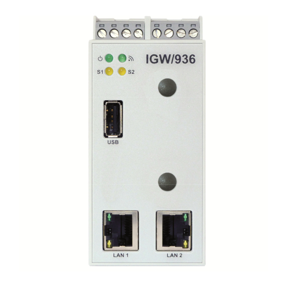
Page 18: Led Functions
IGW/936 – First Steps LED FUNCTIONS Description Flash Power No Power Power On System Not ready Booting Ready VPN state Connecting Ready Table 1: LED functions The LED S2 shows the VPN connection state by different flashing. The following table de- scribes the functions of the particular LED signals. -
Page 19: Trouble Shooting Ip Address Problems
If the IP addresses of LAN1 and LAN2 are not configured properly it is possible, that the SSV/WebUI (the configuration user interface) of the IGW/936 cannot be accessed anymore. In that case it is necessary to restore the factory settings of the IGW/936. To do so please follow these steps: 1. -
Page 20: Helpful Literature
2023-07-11 Removed information about DVI The contents of this document are subject to change without prior notice. SSV does not assume any liability and does not guarantee that the presented information is accurate or complete. The information in this document is provided 'as is' without warranty of any kind. Some names within this document may be trademarks of their respective holders.
Need help?
Do you have a question about the IGW/936 and is the answer not in the manual?
Questions and answers