Table of Contents
Advertisement
Quick Links
Remote Access Gateway IGW/925-W
with DIL/NetPC ADNP/9200
Hardware Reference
SSV Embedded Systems
Dünenweg 5
D-30419 Hannover
Phone: +49 (0)511/40 000-0
Fax:
+49 (0)511/40 000-40
Document Revision: 1.1
E-mail: sales@ssv-embedded.de
Date: 2015-08-26
F
.
-
.
OR FURTHER INFORMATION REGARDING OUR PRODUCTS PLEASE VISIT US AT WWW
SSV
EMBEDDED
DE
Advertisement
Table of Contents

Subscribe to Our Youtube Channel
Related Manuals for SSV IGW/925-W


Summary of Contents for SSV IGW/925-W
- Page 1 Remote Access Gateway IGW/925-W with DIL/NetPC ADNP/9200 Hardware Reference SSV Embedded Systems Dünenweg 5 D-30419 Hannover Phone: +49 (0)511/40 000-0 Fax: +49 (0)511/40 000-40 Document Revision: 1.1 E-mail: sales@ssv-embedded.de Date: 2015-08-26 OR FURTHER INFORMATION REGARDING OUR PRODUCTS PLEASE VISIT US AT WWW...
-
Page 2: Table Of Contents
Remote Access Gateway IGW/925-W – Hardware Reference CONTENT INTRODUCTION ....................... 3 1.1 Safety Guidelines ......................... 3 1.2 Conventions ......................... 3 1.3 Features and Technical Data ....................4 1.4 Main Applications ....................... 5 1.5 Demo Applications ......................5 OVERVIEW ........................6 CONNECTIONS ........................ -
Page 3: Introduction
Remote Access Gateway IGW/925-W – Hardware Reference INTRODUCTION This document describes the hardware components and the necessary cable connections of the Remote Access Gateway IGW/925-W. Safety Guidelines Please read the following safety guidelines carefully! In case of property or personal damage by not paying attention to this document and/or by incorrect handling, we do not assume liability. -
Page 4: Features And Technical Data
Remote Access Gateway IGW/925-W – Hardware Reference Features and Technical Data Processor Manufacturer / Type Atmel AT91RM9200 32-bit ARM9-MCU (DIL/NetPC ADNP/9200 on QIL-128 socket) Clock speed 180 MHz Memory 64 MB SDRAM Flash 32 MB NOR memory Storage media 1x internal microSD card holder with 4 GB card (preconfigured... -
Page 5: Main Applications
Remote Access Gateway IGW/925-W – Hardware Reference Main Applications Remote Access Security Gateway • Industrial Firewall • Application Gateway • Proxy Server • VPN Gateway / Router • Linux Device Server • Demo Applications Smartphone App Backend • Data logger with cloud connection •... -
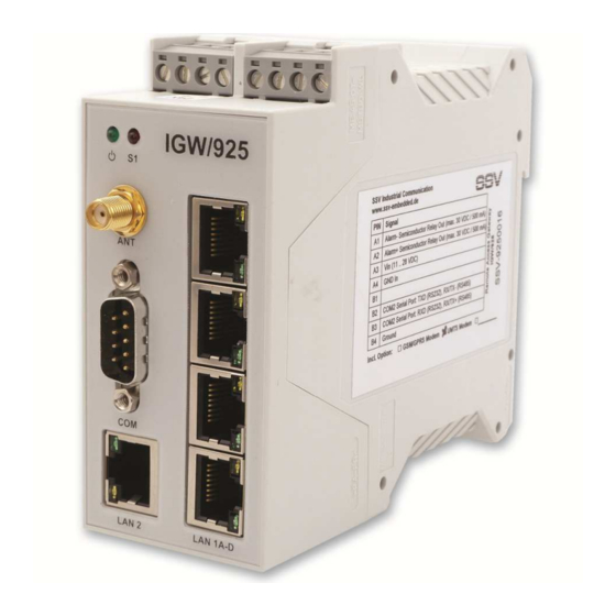
Page 6: Overview
Remote Access Gateway IGW/925-W - Hardware Reference OVERVIEW Figure 1: Overview Remote Access Gateway IGW/925-W D o c u m e n t R e vi s i o n 1 . 1... -
Page 7: Connections
Remote Access Gateway IGW/925-W – Hardware Reference CONNECTIONS Ethernet LAN 1A – D The Ethernet interfaces LAN 1A – D offer each a green LED. It is on when there is a LAN link established and blinks when there is traffic. The yellow LED is not connected. -
Page 8: Serial Port Com1
Remote Access Gateway IGW/925-W – Hardware Reference Serial Port COM1 The serial port COM1 is a standard Sub-D connector. Pin Name Function 1 DCD COM1 Serial Port, DCD pin (RS232) 2 RXD COM1 Serial Port, RXD pin (RS232) 3 TXD... -
Page 9: Serial Port Com2
Remote Access Gateway IGW/925-W – Hardware Reference Serial Port COM2 To create an RS232 serial link on port COM2 of the Remote Access Gateway IGW/925-W connect the adapter cable and the null-modem cable like shown in the figure below. Figure 2: RS232 link on serial port COM2... -
Page 10: Power Supply
Remote Access Gateway IGW/925-W – Hardware Reference Power Supply The Remote Access Gateway IGW/925-W needs a supply voltage of 11 .. 28 VDC to work. Use the power adapter cable to provide the system with the necessary power like shown in the figure below. -
Page 11: Semiconductor Relay Output
Remote Access Gateway IGW/925-W – Hardware Reference Semiconductor Relay Output The Remote Access Gateway IGW/925-W offers a semiconductor relay output to switch an external alarm device with up to 30 VDC and 500 mA on and off. Figure 4: Connecting an external alarm device... -
Page 12: Helpful Literature
Remote Access Gateway IGW/925-W – Hardware Reference HELPFUL LITERATURE • IGW/92X-W first steps • E2W/ESL2 hardware reference • DIL/NetPC ADNP/9200 hardware reference CONTACT SSV Embedded Systems Dünenweg 5 D-30419 Hannover Phone: +49 (0)511/40 000-0 Fax: +49 (0)511/40 000-40 E-mail: sales@ssv-embedded.de Internet: www.ssv-embedded.de...
Need help?
Do you have a question about the IGW/925-W and is the answer not in the manual?
Questions and answers