Table of Contents
Advertisement
Quick Links
Advertisement
Table of Contents

Related Manuals for Magtrol 3411


Summary of Contents for Magtrol 3411
- Page 1 Model 3411 Torque Display User’s Manual...
- Page 2 While every precaution has been exercised in the compilation of this document to ensure the accuracy of its contents, Magtrol, Inc. assumes no responsibility for errors or omissions. Additionally, no liability is assumed for any damages that may result from the use of the information contained within this publication.
-
Page 3: Safety Precautions
Safety Precautions 1. Make sure that all Magtrol Torque Transducers and electronic products are earth-grounded, to ensure personal safety and proper operation. 2. Make sure that torque transducers and motors under test are equipped with appropriate safety guards. -
Page 4: Revisions To This Manual
The contents of this manual are subject to change without prior notice. Should revisions be necessary, updates to all Magtrol User’s Manuals can be found at Magtrol’s web site at www.magtrol.com/support/manuals.htm. Please compare the date of this manual with the revision date on the web site, then refer to the manual’s Table of Revisions for any changes/updates that have been made since this edition. -
Page 5: Table Of Contents
CoNVENTIoNS USED IN ThIS MANUAL ........................VI 1. introduCtion ..........................1 1.1 UNPACkINg YoUR 3411 ToRqUE DISPLAY ......................1 1.2 FEATURES oF ThE 3411 ToRqUE DISPLAY ......................1 1.3 DATA ShEET ................................3 2. Controls ............................6 2.1 FRoNT PANEL ................................6 2.2 REAR PANEL ................................ - Page 6 ......................34 b.1 3411 MENU STRUCTURE ............................34 serviCe information ........................36 RETURNINg MAgTRoL EqUIPMENT FoR REPAIR AND/oR CALIbRATIoN ............. 36 RETURNINg EqUIPMENT To MAgTRoL, INC. (UNITED STATES) ..............36 RETURNINg EqUIPMENT To MAgTRoL SA (SWITzERLAND) ..............36...
- Page 7 Figure 4–11 TM Invert Setup ............................17 5. Computer Controlled operation Figure 5–1 Authentification Window .........................18 Figure 5–2 Magtrol 3411 home web page ........................18 Figure 5–3 Network Settings web page ........................19 Figure 5–4 Torque Display Input web page ......................19 Figure 5–2 Driver Installation Window ........................20 Figure 5–3 Installation Options Window ........................21...
-
Page 8: Preface
Who should use this manual This manual is intended for bench test operators who are going to use the 3411 Torque Display in conjunction with any Magtrol TM In-Line Torque Transducer and TF Torque Flange Sesnor. -
Page 9: Conventions Used In This Manual
Magtrol Model 3411 Torque Display Preface Conventions used in this manual The following symbols and type styles may be used in this manual to highlight certain parts of the text: Note: This is intended to draw the operator’s attention to complementary information or advice relating to the subject being treated. -
Page 10: Introduction
Introduction unpaCking your 3411 torque display Your 3411 Torque Display was packaged in reusable, shock resistant packing material that will protect the instrument during normal handling. 1. Make sure the carton contains the following: Line cord USb Cable 3411 Torque Display... - Page 11 Chapter 1 – Introduction Magtrol Model 3411 Torque Display • Torque: Analog, raw sensor output • Speed output; analog or digital, user selectable • BITE: Built-In Test Equipment • Overload Indication • Tare Function • High Speed Data Acquisition: Up to 500 torque and speed points per second with time stamp •...
-
Page 12: Data Sheet
Torque: Analog, raw sensor output • Speed output; analog or digital, user selectable • BITE: Built-In Test Equipment • Overload Indication • Tare Function TORQUE 7 SOFTWARE • Includes Magtrol Torque 7 Software • High Speed Data Acquisition: Up to 500 torque and ® Magtrol’s Torque 7 Software is a user-friendly LabView speed points per second with time stamp executable program, used to automatically collect torque, speed • Rack mount or handle versions available and mechanical power data. The data can be printed, displayed ® graphically or quickly saved as a Microsoft Excel spreadsheet. DESCRIPTION Standard features of Torque 7 include: • Measured Parameter vs. Time Magtrol’s Model 3411 Torque Display is designed for use with • Adjustable Sampling Rates all Magtrol TM, TMHS, TMB and TF Torque Transducers. - Page 13 Chapter 1 – Introduction Magtrol Model 3411 Torque Display Specifications 3411 MEASUREMENT CHARACTERISTICS ENVIRONMENT Maximum Speed / Operating Temperature 5 ºC to 50 ºC 199,999 rpm / 199,999 Hz Input Frequency Relative Humidity < 80% Speed: 0.01% of reading from Temperature Coefficient 0.001% (5 ºC to 50 ºC)
- Page 14 Magtrol Model 3411 Torque Display Chapter 1 – Introduction Ordering Information 3411 REAR PANEL Torque Speed Output Output USB connection Transducer connection - For Use With Any Magtrol TM, TMHS,TMB or Ethernet TF Torque Transducer connection (or other brand torque sensor)
-
Page 15: Controls
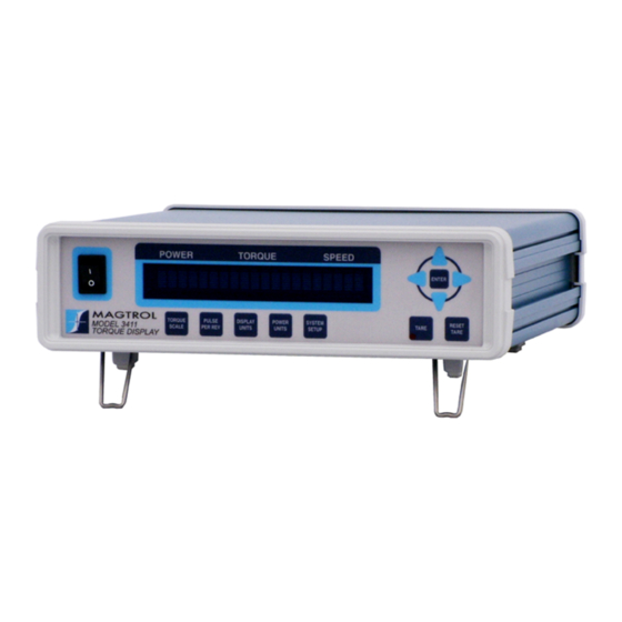
2. Controls front panel The front panel contains a Vacuum Fluorescent Display (VFD) that provides information about the control functions and torque transduce. Figure 2–1 Front Panel The buttons from left to right, top to bottom are: • POWER SWITCH •... - Page 16 Magtrol Model 3411 Torque Display Chapter 2 – Controls button to use function RIGHT Press. Moves the cursor right. ENTER Press. Accepts current selection. xx.xx N·m/5 V TORQUE Press. Use TORQUE SCALE to enter the rated torque SCALE of the attached transducer.
-
Page 17: Rear Panel
Chapter 2 – Controls Magtrol Model 3411 Torque Display rear panel The rear panel provides connectors and receptacles for connecting to appropriate equipment. Figure 2–2 Rear Panel 2.2.1 anel nPuts and utPuts Attach Ethernet cable here. -
Page 18: Figure 2-5 Transducer Connector
Magtrol Model 3411 Torque Display Chapter 2 – Controls Connect transducer signal cable here. TRANSDUCER 1. N/C 5 V COM 2. TACH B 3. +24 VDC TACH A 4. +24 VDC COM 5. +24 VDC COM BITE 6. N/C TORQUE COMMON 7. -
Page 19: Installation/Configuration
To make sure that the 3411 is operational, a Magtrol torque sensor must be installed and connected to the 3411. 1. Connect the 3411 to the torque transducer using a 14-pin to 6-pin signal cable. Figure 3–1 Cable and Connection Diagrams... -
Page 20: Main Menu
TORQUE SPEED FW REVXX FPGA REVXX Figure 3–3 Title Display 2 (5 seconds) 3.1.3 When the 3411 is completely powered up and ready for use, the Main Menu will appear on the dispay. POWER TORQUE SPEED +0.000 0.000 Figure 3–4 Main Menu... -
Page 21: Manually Controlled Operation
3. Press and release ENTER button to save and return to the Main Menu. 4.1.2 uLSe etup Selects the Pulse per Rev for the 3411 Display. 1. Press and release PULSE PER REV button. The display will appear as follows: POWER TORQUE... -
Page 22: Power Units Setup
2. Press and release the UP/DoWN arrow buttons until desired power unit appears in display. 3. Press and release ENTER button to save and return to the Main Menu. 4.1.5 ySteM etup Selects the display options for the 3411 Display. options include: • BITE • USER SETUP •... -
Page 23: Figure 4-5 Bite Setup
When the bITE function is activated the software will turn on an NPN transistor internal to the 3411 that is in an open collector configuration. This output, or collector, is found on pin 12 of the 14-pin connector on the back of the unit. This signal is routed to the transducer and will activate internal circuitry to output a test signal. -
Page 24: Figure 4-7 Ip Address View
4.1.5.5 Contrast The 3411 is shipped with the Contrast programmed to the lowest setting in order to prolong display life. If it is necessary to increase the Contrast for improved readability, execute the following steps: 1. Press and release SYSTEM SETUP button. -
Page 25: Figure 4-10 Analog Speed Bnc Output Setup
Chapter 4 – Manually Controlled Operation Magtrol Model 3411 Torque Display 4. Press and release UP/DoWN arrow buttons until the desired contrast setting shows in the display. 5. Press and release ENTER to save and return to the Main Menu. -
Page 26: Figure 4-11 Tm Invert Setup
4.1.6 unction The calibrated offset of the 3411 may be changed using the tare function. To set: 1. Press TARE button. 2. The red LED light will turn on and the unit will take the current value of the torque input and make it the new zero. -
Page 27: Computer Controlled Operation
5. Computer Controlled Operation The 3411 Torque Display can be used with a personal computer for standard or custom torque and encoder setups. Using the 3411 with a computer enables the unit to perform at its full capacity. about the ethernet interfaCe Connect one Ethernet cable terminal to 3411 RJ45 interface, and another terminal to Ethernet RJ45 on wall outlet or Ethernet switch. -
Page 28: Figure 5-3 Network Settings Web Page
Magtrol Model 3411 Torque Display Chapter 5 – Computer Controlled Operation Press key, to return to the home web page. Figure 5–3 Network Settings web page In the home web page, press “TSP” to display the torque, speed and power web page. Select the “Periodic”... -
Page 29: About The Usb Interface
The USb interface is standard on the 3411 Torque Display. There is a need to set this up. The USb interface will be converted to a serial port in the PC. The USb driver must be installed in order for the 3411 to communicate with the PC. -
Page 30: Figure 5-3 Installation Options Window
Magtrol Model 3411 Torque Display Chapter 5 – Computer Controlled Operation Figure 5–3 Installation Options Window 4. Click the Next button. The following screen will display. The driver will be installed. Figure 5–4 Installation Finish Window 5. Click Finish button, “Found new hardware” will show in right corner. Then USb driver has... -
Page 31: Usb Driver Setup For Windows7/8 64Bit
Copy the 3411 USb driver files from the Magtrol Manual CD at programs\3411USb Driver\ directory into local drive of your PC. 1. Run CP210xVCPInstaller_x64.exe. 2. Power on the 3411. A window in the right corner will show “Installing device driver software” and then show “Magtrol 3411 CP210x USb to UART bridge(CoM#)”. 5.2.3... -
Page 32: Communication Commands
Magtrol Model 3411 Torque Display Chapter 5 – Computer Controlled Operation 5.3.1 ommUnication ommanDS Command function explanation Code Returns Magtrol identification *IDN? Example: 3411 A0 B0 and software revision. Output Data prompt to return data string with this format: SxxxxxxTxxxxxRcrlf... -
Page 33: Setup Commands
Chapter 5 – Computer Controlled Operation Magtrol Model 3411 Torque Display 5.3.2 etUp ommanDS Command function explanation Code Values for # are: 0 = None 4 = 20 Hz Sets filter 1 = 2 Hz 5 = 50 Hz 2 = 5 Hz... -
Page 34: Lan Setup Commands
Magtrol Model 3411 Torque Display Chapter 5 – Computer Controlled Operation 5.3.3 Lan S etUp ommanDS Command Code function explanation DHCP# Enables/Disables DHCP use. Values for # are: You must send the “UPD” 1 = Enable command after sending 0 = Disable DHCP# for the change to take place. -
Page 35: Calibration And Miscellaneous Commands
Chapter 5 – Computer Controlled Operation Magtrol Model 3411 Torque Display Command Code function explanation WHOST, Save new local host name xxxxxxxxxxxxxxx: XXXXXXXXXXXXXXX to non-volatile memory and String of up to 15 characters. activate new host name Must start with letter (A-Z) May contain letters, numbers (0-9), or dashes (“-”) -
Page 36: Output Binary Table
Magtrol Model 3411 Torque Display Chapter 5 – Computer Controlled Operation output binary table number data description data type TimeH Time stamp: the first 32 bit value Integer TimeL Time stamp: the last 32 bit value Integer Display speed Speed derived by using a 0.2 second... -
Page 37: Calibration
6. Calibration Closed-box Calibration The 3411 features closed-box calibration. The advantage of closed-box calibration is that the user does not have to disassemble the case or make mechanical adjustments. The torque readout can be calibrated using external reference sources. Correction factors for offset and gain are stored in nonvolatile memory. -
Page 38: Speed Dac Calibration
Magtrol Model 3411 Torque Display Chapter 6 – Calibration NoTE: Turn off filters before begining the calibration process. 1. Send the command MoDE1 to the unit via USb. 2. Send the command CAL to the unit via the USb. 3. The response will be zERo VoLTS. - Page 39 Chapter 6 – Calibration Magtrol Model 3411 Torque Display 6. The response will be CAL CoMPLETE. 7. Send the command MoDE0 to the unit via USb.
-
Page 40: Theory
7. Theory filter parameters The Digital Filters of the 3411 are used to remove undesired noise from the TSC inputs. This noise could be conducted from an undesired measured signal such as mechanical vibration or other electrical sources. The input to the A/D converter internal to the 3411 has a traditional analog filter that is comprised of the following characteristics: •... -
Page 41: Troubleshooting
Check: • Baud rate Setup error and/or hardware No USB communication. • Cable attachment from fault. Torque Display to USB interface port of computer If you require additional assistance, please contact Magtrol Customer Service at 1-716-668-5555. -
Page 42: Appendix A: Schematics
Appendix A: Schematics 3411 sChematiC... -
Page 43: Appendix B: Menu Structure
Appendix B: Menu Structure 3411 menu struCture... - Page 44 Magtrol Model 3411 Torque Display Appendix B: Menu Structure...
-
Page 45: Service Information
Magtrol, Inc. in the United States or Magtrol SA in Switzerland. returning equipment to magtrol, inc. (united states) When returning equipment to Magtrol, Inc.’s factory in the United States for repair and/or calibration, a completed Return Material Authorization (RMA) form is required. - Page 46 Testing, Measurement and Control of Torque-Speed-Power • Load-Force-Weight • Tension • Displacement www.magtrol.com MAgTROl InC MAgTROl SA subsidiaries in: 70 Gardenville Parkway Route de Montena 77 Germany • France China • India Buffalo, New York 14224 USA 1728 Rossens / Fribourg, Switzerland...
Need help?
Do you have a question about the 3411 and is the answer not in the manual?
Questions and answers