
Subscribe to Our Youtube Channel
Related Manuals for Magtrol 6510e


Summary of Contents for Magtrol 6510e
- Page 1 Model 6510e Single-Phase Power Analyzer User’s Manual Via Paolo Uccello 4 - 20148 Milano Tel +39 02 48 009 757 Fax +39 02 48 002 070 info@dspmindustria.it www.dspmindustria.it...
- Page 2 While every precaution has been exercised in the compilation of this document to ensure the accuracy of its contents, Magtrol, Inc. assumes no responsibility for errors or omissions. Additionally, no liability is assumed for any damages that may result from the use of the information contained within this publication.
-
Page 3: Safety Precautions
1. Make sure that all Magtrol dynamometers and electronic products are earth-grounded, to ensure personal safety and proper operation. 2. Securely ground the 6510e Power Analyzer case by connecting a good earth ground at the ground stud located on the rear panel of the unit. Use a number 12 AWG, or larger wire. -
Page 4: Revisions To This Manual
The contents of this manual are subject to change without prior notice. Should revisions be necessary, updates to all Magtrol User’s Manuals can be found at Magtrol’s web site at www.magtrol.com/support/manuals.htm. Please compare the date of this manual with the revision date on the web site, then refer to the manual’s Table of Revisions for any changes/updates that have been made since this edition. -
Page 5: Table Of Contents
CoNVENTIoNS USED IN ThIS MANUAL ........................ VIII 1. introduCtion ..........................1 1.1 UNPACkING YoUR 6510e PoWER ANALYzER ..................... 1 1.2 NEW FEATURES oF ThE 6510e PoWER ANALYzER ................... 1 1.3 DATA ShEET ................................2 2. Controls ............................5 2.1 FRoNT PANEL ................................5 2.2 FRoNT PANEL CoNTRoLS AND bUTToNS ...................... - Page 6 5.2 AboUT ThE RS-232 INTERFACE ........................... 38 5.2.1 CoNNECTIoN ............................. 38 5.2.2 CoMMUNICATIoN PARAMETERS ......................39 5.2.3 bAUD RATE ..............................39 5.3 ChECkING ThE 6510e-To-PC CoNNECTIoN ..................... 39 5.4 DATA FoRMAT ................................40 5.4.1 oT ExAMPLE ............................. 40 5.4.2 oE ExAMPLE ............................. 41 5.4.3 oA/oV/oW/oF ExAMPLE .........................
- Page 7 A.6 kEY PAD ..................................58 A.7 ANALoG oUTPUT ..............................59 glossary............................63 index ..............................64 serviCe information ........................66 RETURNING MAGTRoL EqUIPMENT FoR REPAIR AND/oR CALIbRATIoN ............. 66 RETURNING EqUIPMENT To MAGTRoL, INC. (UNITED STATES) ..............66 RETURNING EqUIPMENT To MAGTRoL SA (SWITzERLAND) ..............66...
-
Page 8: Table Of Figures
Table of Contents Magtrol Model 6510e Single-Phase Power Analyzer table of figures 2. Controls Figure 2–1 Front Panel ..............................5 Figure 2–2 Secondary Function Menu ........................6 Figure 2–3 Device Setup Menu ...........................9 Figure 2–4 Rear Panel ..............................10 Figure 2–5 Input Module ............................10 Figure 2–6 RS-232C Interface ..........................11... -
Page 9: Preface
Who should use this manual This manual is intended for those operators who are planning to use the Model 6510e Power Analyzer for power measurement purposes either as a stand-alone instrument or in conjunction with any Magtrol hysteresis, Eddy-Current or Powder brake Dynamometer, any Magtrol Dynamometer Controller and M-TEST Motor Testing Software. -
Page 10: Conventions Used In This Manual
Preface Magtrol Model 6510e Single-Phase Power Analyzer Conventions used in this manual The following symbols and type styles may be used in this manual to highlight certain parts of the text: Note: This is intended to draw the operator’s attention to complementary information or advice relating to the subject being treated. -
Page 11: Introduction
Save all shipping cartons and packaging material for reuse when returning the instrument for calibration or servicing. neW features of the 6510e poWer analyzer Magtrol’s new Model 6510e Single-Phase Power Analyzer is an upgraded version of the 6510. The new features that make the unit unique include: •... -
Page 12: Data Sheet
• HVAC Equipment • Calibration Certificate: NIST Traceable Rack Mounting: 19” (482.6 mm) with handles • The 6510e’s/6530’s data transfer rate makes it ideal for both static and dynamic tests. system ConFigurations Motor Under Test DSP7001 Dynamometer Controller VOLTS AMPS... - Page 13 Continuous or Cycle-by-Cycle Measurement Mode Power Factor rear panel Phase Input Module External Sync. Input RS-232C and GPIB/IEEE-488 Interfaces 3 for 6530 (as shown) , 1 for 6510e (Cycle-by-Cycle Synchronization) (for Connection to Personal Computer) External Voltage Current Optional Analog Output...
- Page 14 All shunts are calibrated on equipment with current certifications traceable to N.I.S.T. • Industry Standard 25-Pin Connection The Analog Output can be used along with a 6510e or 6530 SPECIFICATIONS Power Analyzer to output information to a strip recorder or HA Series...
-
Page 15: Controls
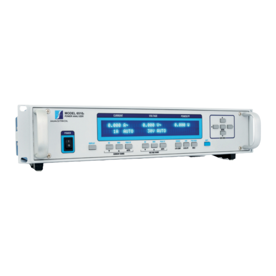
2. Controls front panel The front panel provides a power switch, sixteen control buttons and a Vacuum Fluorescent Display (VFD). MODEL 6510e POWER ANALYZER ENTER USER MENU DISPLAY PEAK-CF PEAK-CF SOURCE PEAK HOLD SHIFT AUTO AUTO CYC-CONT W-VA-PF HOLD CURRENT RANGE VOLTAGE RANGE Figure 2–1 Front Panel... -
Page 16: Enabling Secondary Functions
Chapter 2 – Controls Magtrol Model 6510e Single-Phase Power Analyzer 2.2.1 nabling Econdary unctionS To enable the secondary function of the double-function control buttons: 1. Press the blue ShIFT button and release it. The word “ShIFT” appears in the display:... - Page 17 Magtrol Model 6510e Single-Phase Power Analyzer Chapter 2 – Controls 2.2.2.2 Double-Function Buttons button to use function DISPLAY Press SHIFT and release; then Shows custom display. press this button. (For further instruction, see Section 3.3.7.4 - Custom Display.) PHASE Press this button.
-
Page 18: Vacuum Fluorescent Display (Vfd)
EttingS The 6510e Power Analyzer is shipped with the Contrast Setting on low in order to prolong display life. If it is necessary to increase the Contrast for improved readability, execute the following steps using the USER MENU located on the front panel of the unit. -
Page 19: Display Guide
2.3.2 iSPlay uidE Following is a reference for symbols, abbreviations and messages that are used in the 6510e. symbol/abbreviation/message meaning SHIFT Shift button was pressed... -
Page 20: Rear Panel
Chapter 2 – Controls Magtrol Model 6510e Single-Phase Power Analyzer rear panel The rear panel provides connectors and receptacles for connecting to appropriate equipment. VOLTS AMPS CAUTION: DOUBLE POLE FUSING 20VA 50/60Hz EARTH 750 V 20 A GROUND MAX. MAX. -
Page 21: Figure 2-6 Rs-232C Interface
Magtrol Model 6510e Single-Phase Power Analyzer Chapter 2 – Controls ANALoG Connects strip chart recorder or data acquisition system, providing 3 oUTPUT analog outputs. (optional) • Volts • Amps • Watts ±10 volts = range See Section 7.1 – Analog Outputs for detailed information about this option. - Page 22 Chapter 2 – Controls Magtrol Model 6510e Single-Phase Power Analyzer PoWER Attach power cord here. EARTh Attach earth ground here. GRoUND WARNING: mAke suRe ThAT All mAGTRol dyNAmomeTeRs ANd elecTRoNIc pRoducTs ARe eARTh-GRouNded, To eNsuRe peRsoNAl sAfeTy ANd pRopeR opeRATIoN. secuRely GRouNd The...
-
Page 23: Installation/Configuration
The 6510e will operate from 85 to 264 VAC on a 50/60 hz line voltage. 3.1.2 After turning the power on to the 6510e, the display panel will show all segments of the VFD (series of rectangles), indicating that the 6510e is downloading the program. -
Page 24: Main Menu
Figure 3–3 Revision Display 3.1.3 When the 6510e is completely powered up and ready for use, the main menu will appear on the display. The main menu is defined by the last configuration that was used. This could include one of two different menus: phase or custom. -
Page 25: Protecting Your 6510E
If a circuit breaker is installed, it must be installed on the load side of the 6510e (downstream). This will keep the low impedance of the input line connected to the 6510e for surge suppression. If the line side must also contain a breaker, it should be delayed in operation to open after the load side breaker has opened. -
Page 26: Circuit Breakers
The voltage sense lines are connected at the line side of the circuit breaker to help prevent inductive transients from entering the 6510e as the circuit breaker opens. Make sure that connections from the circuit breaker to the load are heavy conductors and short as possible. -
Page 27: Testing Instrumentation Setup
Magtrol Model 6510e Single-Phase Power Analyzer Chapter 3 – Installation/Configuration testing instrumentation setup before the 6510e can be utilized, it must be configured and connected to the devices intended for power measurement. 3.3.1 iring The 6510e has the ability to support a 1-phase, 2-wire wiring connection. -
Page 28: Measurement Filter
Chapter 3 – Installation/Configuration Magtrol Model 6510e Single-Phase Power Analyzer 3.3.1.2 Software Configuration The 6510e wiring mode default is set at 1-phase, 2-wire, therefore no software configuration is needed. 3.3.2 EaSurEMEnt iltEr During the RMS calculations, in the signal-processing path, there is a digital low-pass filter. The user can program the filter’s cutoff frequency. -
Page 29: External Sensor
Magtrol Model 6510e Single-Phase Power Analyzer Chapter 3 – Installation/Configuration 3.3.3 xtErnal EnSor If currents continuously reach above 20 amps, an external sensor must be used. 3.3.3.1 Hardware Connection In the wiring mode, the amp meter may be replaced. The following diagram illustrates the connection. -
Page 30: Figure 3-11 External Sensor Scale Factor Setup Menu
Magtrol Model 6510e Single-Phase Power Analyzer 3.3.3.2 Software Configuration To configure the 6510e external sensor, complete the following steps utilizing the USER MENU located on the front panel of the unit. 1. Turn on the 6510e. See Section 3.1 – Powering Up the 6510e. -
Page 31: Amp Scaling
3.3.4.2 Software Configuration To configure the 6510e amp scaling for a current transformer, complete the following steps utilizing the USER MENU located on the front panel of the unit. 1. Turn on the 6510e. See Section 3.1 – Powering Up the 6510e. -
Page 32: Figure 3-14 Amp/Volt Scaling Activated
Chapter 3 – Installation/Configuration Magtrol Model 6510e Single-Phase Power Analyzer 6. To turn scaling oN, press the PEAk-CF button under oFF until oN is reached. 7. Press ENTER to exit the Device Setup Menu. Note: When amps scaling has been activated, “... -
Page 33: Volts Scaling
3.3.5.2 Software Configuration To configure the 6510e volt scaling for a potential transformer, complete the following steps utilizing the USER MENU located on the front panel of the unit. 1. Turn on the 6510e. See Section 3.1 – Powering Up the 6510e. -
Page 34: Phase Setup
Chapter 3 – Installation/Configuration Magtrol Model 6510e Single-Phase Power Analyzer 3.3.6 haSE EtuP once the wiring mode, measurement filter, external sensor, amp scaling and volt scaling have been connected and configured, the unit is ready to be configured for phase setup. -
Page 35: Special Functions
Magtrol Model 6510e Single-Phase Power Analyzer Chapter 3 – Installation/Configuration 3.3.7 PEcial unctionS 3.3.7.1 Hold • Freezes display values. • To set, press and release HOLD button. The display will appear as follows, indicating that the hold function is enabled. -
Page 36: Figure 3-19 Peak Hold Clear Display
Chapter 3 – Installation/Configuration Magtrol Model 6510e Single-Phase Power Analyzer 3.3.7.3 Peak Hold • Clears peak hold/inrush reading. • To enable, press SHIFT button and release, then press PEAK HOLD. The display will flash the following, then return to the main menu. -
Page 37: Operating Principles
4. Operating Principles analog proCessing 4.1.1 oltS The volts signal is brought in through a precision voltage divider of 2 M and 2.4 k resistors. The gain is 0.0012. This signal is buffered (GAIN = 1) and passed into a programmable gain section. The gains for the voltage ranges are given below. -
Page 38: Amps
Chapter 4 – Operating Principles Magtrol Model 6510e Single-Phase Power Analyzer 4.1.2 The amps signal is brought in through a precision shunt of 0.012 ohms. This signal is amplified by 2 and passed into a programmable gain section. The gains for the voltage ranges are given below. -
Page 39: External Shunt
Magtrol Model 6510e Single-Phase Power Analyzer Chapter 4 – Operating Principles 4.1.3 xtErnal hunt The external shunt signal is brought in through a precision voltage divider of 9.1 k and 9.1 k resistors. The gain is 0.50. This signal is buffered and passed into a programmable gain section. The gains for the voltage ranges are given below. -
Page 40: Ac Details
Chapter 4 – Operating Principles Magtrol Model 6510e Single-Phase Power Analyzer 4.2.1 ac d EtailS 4.2.1.1 Interrupt Driven The power analyzer will automatically update its data every 4.469 microseconds by completing the following sequence of events: • The volts input is read and checked for an over range condition. The offset is then added to the reading and the reading is negated and saved. - Page 41 Magtrol Model 6510e Single-Phase Power Analyzer Chapter 4 – Operating Principles 4.2.1.2 Main Program The main program reads that a sample is ready. Divide the V² register by 256. Store V² in a 24-bit register. (See Section 4.2.3 – Round-Off Error).
-
Page 42: Dc Details
Chapter 4 – Operating Principles Magtrol Model 6510e Single-Phase Power Analyzer 4.2.2 dc d EtailS 4.2.2.1 Interrupt Driven The power analyzer will automatically update its data every 4.469 microseconds by completing the following sequence of events: • The volts input is read and checked for an over range condition. The offset is then added to the reading and the reading is negated and saved. - Page 43 Magtrol Model 6510e Single-Phase Power Analyzer Chapter 4 – Operating Principles 4.2.2.2 Main Program The main program reads that a sample is ready. Divide the V register by 256. Store V in a 24-bit register. The result is appended to a 32 word circular buffer.
-
Page 44: Round-Off Error
Chapter 4 – Operating Principles Magtrol Model 6510e Single-Phase Power Analyzer 4.2.3 ound rror The interrupt routine adds 256 56-bit squared readings. This reading is then divided by 256 and put into a 24-bit register. Some error occurs during the move to the 24-bit register. The result of the 16-bit A/D conversion is put into the high 16 bits of a 24-bit register. -
Page 45: Peak Hold / Inrush Current
Peak hold/inrush current allows the 6510e to store the highest value read in a designated period of time, the designated period of time being the time span since the last peak hold clear occurred. Values include amps, watts and volts in any preferred combination. See Section 3.3.7.3 – Peak Hold. -
Page 46: Rms
Chapter 4 – Operating Principles Magtrol Model 6510e Single-Phase Power Analyzer 4.3.4 See Section 4.2.1 – AC Details 4.3.5 rESt actor The crest factor measurement is determined by dividing the peak measurement by the RMS measurement. See the following graph for reference. -
Page 47: Computer Controlled Operation
5. Computer Controlled Operation Using the 6510e with a personal computer (PC) enables the unit to perform at its full capacity. about the gpib interfaCe Magtrol prefers the GPIb (General Purpose Interface bus)/IEEE-488 Standard for computer-to- instrument interfacing because: •... -
Page 48: About The Rs-232 Interface
Some PC interfaces can access from one to fifteen 4-bit primary addresses. other interfaces can access as many as thirty-one 5-bit primary addresses. The 6510e uses the 4-bit format. For setup, complete the following instructions utilizing the USER MENU control buttons. -
Page 49: Communication Parameters
Make sure that the 6510e and its host computer are communicating before acquiring data. 1. Make sure the primary GPIb address is set correctly for the 6510e. 2. Set the input variable to 15 characters (13 variable characters and the two required data termination characters CR and LF. -
Page 50: Data Format
Chapter 5 – Computer Controlled Operation Magtrol Model 6510e Single-Phase Power Analyzer data format • All measurement values are returned as an ASCII-string floating point in E notation. • The same data format will be used for both IEEE-488 and RS-232 interface. See Section 5.6 –... -
Page 51: Oe Example
Use the following information to answer the formatting questions asked when installing your GPIb software. All GPIb data acquisition systems require the use of data termination characters. The 6510e uses the GPIb standard termination characters Carriage Return (CR) and Line Feed (LF). Provide them in that order. -
Page 52: 6510E Communication Commands
Chapter 5 – Computer Controlled Operation Magtrol Model 6510e Single-Phase Power Analyzer 6510e CommuniCation Commands Ieee-488 Address: 0-15 Terminator: carriage return followed by a line feed Rs-232 baud Rate: 300, 600, 1200, 2400, 4800, 9600, 19.2 k, 115.2 k Terminator:... - Page 53 Magtrol Model 6510e Single-Phase Power Analyzer Chapter 5 – Computer Controlled Operation Command Code function explanation MFm<terminator> Sets the AC and DC "m" indicates the measurement filter low- measurement mode filter. pass frequency (response time). Values for m are: 0 = 1 Hz...
-
Page 54: Data Output Commands
Chapter 5 – Computer Controlled Operation Magtrol Model 6510e Single-Phase Power Analyzer 5.6.2 utPut oMMandS Command Code function explanation OA1,m2<terminator> Requests amp measurement "m2" indicates the measurement value. value. Values for m2 are: 0 = normal (RMS/DC depending on measurement mode setting) -
Page 55: Calibration
6. Calibration Closed-box Calibration The 6510e features closed-box calibration. The advantage of closed-box calibration is that the user does not have to disassemble the case or make mechanical adjustments. Calibration sChedule Calibrate the 6510e: • After any repairs are performed. -
Page 56: Basic Calibration Process
4. Turn the power oN while holding the ShIFT button. See Section 3.1 – Powering Up the 6510e. before the display panel shows the segments of the VFD (series of rectangles), the following display will appear indicating that the instrument has been placed in calibration mode. - Page 57 Magtrol Model 6510e Single-Phase Power Analyzer Chapter 6 – Calibration 5. Set volt and amp range by entering the following command codes. VoLTS => RV1,m2 where m2 = 0 to 3 AMPS => RA1,m2 where m2 = 0 to 3 6.
-
Page 58: Optional Features
7. Optional Features analog outputs An option to the 6510e is an analog output plug-in module that provides 12 channels of analog output corresponding to volts, amps and watts. Each output is capable of, and calibrated to, ± 10 volts. The user may apply a scale factor to all outputs by selecting “Analog outputs” in the USER MENU. -
Page 59: Hardware Connection
9. Replace the top cover by reconnecting the ground strap and replacing the four screws. 10. Finally, plug the line cord in to the back of the unit. When the power is turned on, the 6510e will recognize the card is in place and start sending data to it. -
Page 60: Calibration
7.1.5 alibration 7.1.5.1 Closed-Box Calibration The 6510e features closed-box calibration for the analog output. The advantage of closed-box calibration is that the user does not have to disassemble the case or make mechanical adjustments. 7.1.5.2 Calibration Schedule Calibrate the 6510e analog output board: •... - Page 61 Magtrol Model 6510e Single-Phase Power Analyzer Chapter 7 – Optional Features 7.1.5.4 Basic Calibration Process 1. Turn on the unit with ShIFT button pressed. 2. Send CM1 command. This sets all DAC outputs to 10 volts nominal. 3. Using a volt meter, measure the voltage on the channel.
-
Page 62: Troubleshooting
Setup error and/or hardware Check: fault. • Baud rate of power analyzer. • Pinout of serial cable. • Cable attachment to power analyzer and serial interface port of computer. If you require additional assistance, please contact Magtrol Customer Service at 1-716-668-5555. -
Page 63: Appendix A: Schematics
Appendix A: Schematics main board - dsp, ram, flash... -
Page 64: Main Board - Input/Output, Gpib, Rs-232
Appendix A: Schematics Magtrol Model 6510e Single-Phase Power Analyzer main board - input/output, gpib, rs-232... -
Page 65: Main Board - Fpga
Magtrol Model 6510e SIngle-Phase Power Analyzer Appendix A: Schematics main board - fpga 107 CCLK CCLK I/O54 IRQC 74 PROGRAM PROG I/O55 USB_IRQ 72 DONE I/O56/SGCK3 SCO_V2 36 MODE I/O57 TIO2 +5VD I/O58/PGCK3 SCO_V1 38 N/C2 I/O59 AUX1 34 N/C1... -
Page 66: Input Module - Current
Appendix A: Schematics Magtrol Model 6510e Single-Phase Power Analyzer input module - Current DGND1 28 DGND DVDD AGND7 AGND6 21 AVDD2 AGND5 19 AVDD1 AGND4 15 AVDD AGND3 13 AGND2 10 AGND1 9 AGND... -
Page 67: Input Module - Voltage
Magtrol Model 6510e SIngle-Phase Power Analyzer Appendix A: Schematics input module - voltage DGND1 DGND DVDD AGND7 AGND6 AVDD2 AGND5 AVDD1 AGND4 AVDD AGND3 AGND2 AGND1 AGND... -
Page 68: Key Pad
Appendix A: Schematics Magtrol Model 6510e Single-Phase Power Analyzer key pad... -
Page 69: Analog Output
Magtrol Model 6510e SIngle-Phase Power Analyzer Appendix A: Schematics analog output A.7.1 Analog Output – drawing 1 of 4... - Page 70 Appendix A: Schematics Magtrol Model 6510e Single-Phase Power Analyzer A.7.2 Analog Output – drawing 2 of 4 +15VA BAT54S LT2079 J1-1 U5-A AMPS PHASE 1 J1-14 C22 0.01 -15VA +15VA PAEN BAT54S LT2079 VOUT1 ad7834 VOUT2 J1-2 SYNC SYNC U5-B...
- Page 71 Magtrol Model 6510e SIngle-Phase Power Analyzer Appendix A: Schematics A.7.3 Analog Output – drawing 3 of 4 +15VA BAT54S LT2079 J1-4 U1-A – AMPS PHASE 2 J1-17 C26 0.01 -15VA +15VA BAT54S LT2079 J1-5 PAEN U1-B – VOLTS PHASE 2...
- Page 72 Appendix A: Schematics Magtrol Model 6510e Single-Phase Power Analyzer A.7.4 Analog Output – drawing 4 of 4 +15VA BAT54S LT2079 J1-7 U2-A – AMPS PHASE 3 J1-20 C30 0.01 -15VA +15VA BAT54S LT2079 J1-8 PAEN U2-B – VOLTS PHASE 3...
-
Page 73: Glossary
Following is a list of abbreviations and terms used in this manual. For a list of symbols and abbreviations used on the 6510e display, refer to Section 2.3.2 – Display Guide. Active power ....The sum of the instantaneous volts input multiplied by the instantaneous amps input = true power = watts. -
Page 74: Index
Index Abbreviations Used 9 Data Format 40 Active Power 63 Data output Commands 44 Amp Scaling 21 Data Sheet 2 Amp Scaling Setup Menu 21 Data Termination Characters 41 Amps Gain 28 Digital Processing 29 Amps Input 10 Amps Signal 28 Ext. - Page 75 Magtrol Model 6510e Single-Phase Power Analyzer Index Measurement Filter 18 Measurement Methods 36 Testing Instrumentation Setup 17 Measurement Modes 34 Transient overloads 15 Menus Transient Voltage Suppression 16 Amp Scaling Setup Menu 21 Troubleshooting 52 Analog output Setup Menu 49...
-
Page 76: Service Information
Testing, Measurement and Control of Torque-Speed-Power • Load-Force-Weight • Tension • Displacement Via Paolo Uccello 4 - 20148 Milano Tel +39 02 48 009 757 Fax +39 02 48 002 070 info@dspmindustria.it www.dspmindustria.it...
Need help?
Do you have a question about the 6510e and is the answer not in the manual?
Questions and answers