Table of Contents
Advertisement
Quick Links
Advertisement
Table of Contents

Related Manuals for Magtrol 7500 SERIES


Summary of Contents for Magtrol 7500 SERIES
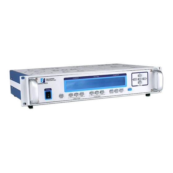
- Page 1 7500 Series Power Analyzer User’s Manual...
- Page 2 While every precaution has been exercised in the compilation of this document to ensure the accuracy of its contents, Magtrol, Inc. assumes no responsibility for errors or omissions. Additionally, no liability is assumed for any damages that may result from the use of the information contained within this publication.
-
Page 3: Safety Precautions
2. Securely ground the 7500 Series Power Wattmeter case by connecting a good earth ground at the ground stud located on the rear panel of the unit. Use a number 12 AWG, or larger wire. -
Page 4: Revisions To This Manual
The contents of this manual are subject to change without prior notice. Should revisions be necessary, updates to all Magtrol User’s Manuals can be found at Magtrol’s web site at www.magtrol.com/support/manuals.htm. Please compare the date of this manual with the revision date on the web site, then refer to the manual’s Table of Revisions for any changes/updates that have been made since this edition. -
Page 5: Table Of Contents
CONVENTIONS USED IN ThIS MANUAL ........................VII 1. introduCtion ..........................1 1.1 UNPACkING YOUR 7500 SERIES POWER ANALYzER ..................1 1.2 NEW FEATURES OF ThE 7500 SERIES POWER ANALYzER ................1 1.3 DATA ShEET ................................2 2. Controls ............................6 2.1 FRONT PANEL ................................6 2.2 FRONT PANEL CONTROLS AND bUTTONS ...................... -
Page 6: Table Of Contents
Table of Contents Magtrol 7500 Series Power Wattmeter 3.3.7 SPECIAL FUNCTIONS ..........................31 4. operating prinCiples .......................33 4.1 ANALOG PROCESSING ............................33 4.1.1 VOLTS ................................33 4.1.2 AMPS ................................34 4.1.3 ExTERNAL ShUNT ........................... 35 4.2 DIGITAL PROCESSING ............................35 4.2.1... -
Page 7: Table Of Figures
CONFIGURATION COMMANDS ..........................61 b.2 DATA OUTPUT COMMANDS ..........................64 serviCe information ........................65 RETURNING MAGTROL EqUIPMENT FOR REPAIR AND/OR CALIbRATION ............. 65 RETURNING EqUIPMENT TO MAGTROL, INC. (UNITED STATES) ..............65 RETURNING EqUIPMENT TO MAGTROL SA (SWITzERLAND) ..............65 table of figures 2. -
Page 8: Magtrol 7500 Series Power Wattmeter
Table of Contents Magtrol 7500 Series Power Wattmeter 4. operating prinCiples Figure 4-1 Peak Example ............................39 Figure 4–2 Peak Hold/Inrush Current Example .......................40 Figure 4–3 Crest Factor Example ..........................41 5. Computer Controlled operation Figure 5–1 GPIB Installation ...........................42 Figure 5–2 GPIB Address Setup Menu ........................43 Figure 5–3 Web Interface Home Page ........................55... -
Page 9: Preface
Who should use this manual This manual is intended for those operators who are planning to use the 7500 Series Power Analyzer for power measurement purposes either as a stand-alone instrument or in conjunction with any Magtrol hysteresis, Eddy-Current or Powder brake Dynamometer, any Magtrol Dynamometer Controller and M-TEST Motor Testing Software. -
Page 10: Conventions Used In This Manual
Magtrol 7500 Series Power Analyzer Preface Magtrol Model 6530 Three-Phase Power Analyzer Conventions used in this manual The following symbols and type styles may be used in this manual to highlight certain parts of the text: Note: This is intended to draw the operator’s attention to complementary information or advice relating to the subject being treated. -
Page 11: Introduction
7500 series poWer analyzer Magtrol’s new 7500 Series Power Analyzer is an upgraded version of the 6510e/6530. The new features that make the unit unique include: peak hold: Allows the unit to store the highest value read since the last peak hold was •... -
Page 12: Data Sheet
DC to 100 kHz AC, the 7500 measures volts, amps, watts, volt-amps, frequency, crest factor, Vpeak, Apeak and power factor in one convenient display. They may be used either as stand-alone instruments or in conjunction with any Magtrol Hysteresis, eddy-Current or Powder Brake Dynamometer; any Magtrol Dynamometer Controller and M-TeST Software for more demanding motor test applications. -
Page 13: Back Panel
3 for 7530 (as shown), 1 for 7510 USB Connection Voltage Ethernet Connection External Input Sensor Input Page 2 / 4 © 2017 MAGTROL | Due to continual product development, Magtrol reserves the right to modify specifications without forewarning. datasheet www.magtrol.com... -
Page 14: Specifications
100 kΩ weight 12.97 lb 5.88 kg Voltage Level TTL / CMOS Maximum Voltage 50 V Page 3 / 4 © 2017 MAGTROL | Due to continual product development, Magtrol reserves the right to modify specifications without forewarning. datasheet www.magtrol.com... -
Page 15: Options And Accessories
InFoRMatIon 7510 Single-Phase Power Analyzer 7530 Three-Phase Power Analyzer Page 4 / 4 © 2017 MAGTROL | Due to continual product development, Magtrol reserves the right to modify specifications without forewarning. datasheet www.magtrol.com MagtrOl Inc phone +1 716 668 5555... -
Page 16: Controls
2. Controls front panel The front panel provides a power switch, sixteen control buttons and a Vacuum Fluorescent Display (VFD). Figure 2–1 Front Panel front panel Controls and buttons The front panel controls and buttons, from left to right, are: •... -
Page 17: Enabling Secondary Functions
Magtrol 7500 Series Power Analyzer Magtrol Model 6530 Three-Phase Power Analyzer Chapter 2 – Controls 2.2.1 nabling Econdary unctionS To enable the secondary function of the double-function control buttons: 1. Press the blue ShIFT button and release it. The word “ShIFT” appears in the display:... - Page 18 Magtrol 7500 Series Power Analyzer Chapter 2 – Controls Magtrol Model 6530 Three-Phase Power Analyzer 2.2.2.2 Double-Function Buttons button to use function DISPLAY Press SHIFT and release; then Shows custom display. press this button. (For further instruction, see Section 3.3.7.4 - Custom Display.)
-
Page 19: Vacuum Fluorescent Display (Vfd)
EttingS The 7500 Series Power Analyzer is shipped with the Contrast Setting on low in order to prolong display life. If it is necessary to increase the Contrast for improved readability, execute the following steps using the USER MENU located on the front panel of the unit. -
Page 20: Display Guide
Magtrol 7500 Series Power Analyzer Chapter 2 – Controls Magtrol Model 6530 Three-Phase Power Analyzer sure the lowest possible setting is used to achieve desired result. Using a setting higher than necessary may cause display segments to burn-in over a period of time, resulting in uneven illumination from segment to segment. -
Page 21: Rear Panel
Magtrol 7500 Series Power Analyzer Magtrol Model 6530 Three-Phase Power Analyzer Chapter 2 – Controls rear panel The rear panel provides connectors and receptacles for connecting to appropriate equipment. Figure 2–4 Rear Panel rear panel inputs and outputs INPUT Contains the Voltage Input, Current Input and External Sensor connectors MODULE for each phase. -
Page 22: Figure 2-6 Gpib/Ieee-488 Interface
Magtrol 7500 Series Power Analyzer Chapter 2 – Controls Magtrol Model 6530 Three-Phase Power Analyzer GPIb/ Use this socket for GPIb cable (meets IEEE-488 specifications). IEEE-488 11 10 1. D1 13. D5 2. D2 14. D6 3. D3 15. D7 4. - Page 23 ANd elecTRoNIc pRoducTs ARe eARTh-GRouNded, To eNsuRe peRsoNAl sAfeTy ANd pRopeR opeRATIoN. secuRely GRouNd The 7500 seRIes poWeR ANAlyzeR cAse by coNNecTING A Good eARTh GRouNd AT The GRouNd sTud locATed oN The ReAR pANel of The uNIT. use A...
-
Page 24: Installation/Configuration
After turning the power on to the 7500, the Initial Display panel will appear: CURRENT VOLTAGE POWER/PF 7500 SERIAL KEYPAD REV xx Figure 3–1 Initial Display followed by the Title Display. CURRENT VOLTAGE POWER/PF MAGTROL 7500 phase POWER analyzer Figure 3–2 Title Display... -
Page 25: Main Menu
Magtrol Model 6530 Three-Phase Power Analyzer Magtrol 7500 Series Power Analyzer Chapter 3 – Installation/Configuration Then an additional display will appear indicating the version of your Magtrol 7500 Series Power Analyzer. CURRENT VOLTAGE POWER/PF magtrol 7500 FW rev: xx fpga rev: xx Figure 3–3 Revision Display... -
Page 26: Protecting Your 7500
Chapter 3 – Installation/Configuration Magtrol Model 6530 Three-Phase Power Analyzer Magtrol 7500 Series Power Analyzer The custom menu can include up to 6 fields with selections dependent on the measurement mode. CURRENT VOLTAGE POWER/PF Figure 3–6 Custom Main Menu proteCting your 7500 before the 7500 is used for power measurement, guidelines regarding transient overloads, current overload, surge protection and circuit breakers must be followed. -
Page 27: Circuit Breakers
Magtrol Model 6530 Three-Phase Power Analyzer Magtrol 7500 Series Power Analyzer Chapter 3 – Installation/Configuration MOV > LINE TO LINE MOV > LINE TO LINE (LINE 1) (LOAD) (LINE 1) (LOAD) NEUTRAL DELTA CONNECTED WYE CONNECTED THREE-PHASE LOAD THREE-PHASE LOAD MOV >... -
Page 28: Testing Instrumentation Setup
Chapter 3 – Installation/Configuration Magtrol Model 6530 Three-Phase Power Analyzer Magtrol 7500 Series Power Analyzer testing instrumentation setup before the 7500 can be utilized, it must be configured and connected to the devices intended for power measurement. 3.3.1 iring The 7500 has the ability to support a combination of up to 3 phases, therefore, there are a number of different ways in which the unit can be wired. -
Page 29: Figure 3-8 Single-Phase, Two-Wire Wiring Schematic
Magtrol Model 6530 Three-Phase Power Analyzer Magtrol 7500 Series Power Analyzer Chapter 3 – Installation/Configuration 1-phase, 2-Wire • Measures single-phase power. • Can be wired on any input module. • The Power Factor is derived from the following equations: Amps Σ = A , Volts Σ... -
Page 30: Figure 3-10 Single-Phase, Three-Wire Wiring Schematic
Chapter 3 – Installation/Configuration Magtrol Model 6530 Three-Phase Power Analyzer Magtrol 7500 Series Power Analyzer 1-phase, 3-Wire • Measures single-phase power. • Utilizes input modules one and three. • The Power Factor is derived from the following equations: Amps Σ = (A )/2, Volts Σ... -
Page 31: Figure 3-12 Three-Phase, Three-Wire Wiring Schematic
Magtrol Model 6530 Three-Phase Power Analyzer Magtrol 7500 Series Power Analyzer Chapter 3 – Installation/Configuration 3-phase, 3-Wire • Measures three-phase power. • Utilizes input modules one and three. • The Power Factor is derived from the following equations: Amps Σ = (A )/2, Volts Σ... -
Page 32: Figure 3-14 Three-Phase, Four-Wire Wiring Schematic
Chapter 3 – Installation/Configuration Magtrol Model 6530 Three-Phase Power Analyzer Magtrol 7500 Series Power Analyzer 3-phase, 4-Wire • Measures three-phase power. • Utilizes all three phases. • The Power Factor is derived from the following equations: Amps Σ = (A )/3, Volts Σ... -
Page 33: Figure 3-16 Three-Voltage, Three-Ampere Wiring Schematic
Magtrol Model 6530 Three-Phase Power Analyzer Magtrol 7500 Series Power Analyzer Chapter 3 – Installation/Configuration 3-volt, 3-Amp • Measures three-phase power. • Utilizes all three phases. • The Power Factor is derived from the following equations: Amps Σ = (A )/3, Volts Σ... -
Page 34: Measurement Filter
Chapter 3 – Installation/Configuration Magtrol Model 6530 Three-Phase Power Analyzer Magtrol 7500 Series Power Analyzer 3.3.1.2 Software Configuration To configure the 7500 to coincide with the wiring on the rear panel, complete the following steps utilizing the USER MENU located on the front panel of the unit. -
Page 35: External Sensor
Magtrol Model 6530 Three-Phase Power Analyzer Magtrol 7500 Series Power Analyzer Chapter 3 – Installation/Configuration 3.3.3 xternaL ensor If currents continuously reach above 20 amps, an external sensor must be used. 3.3.3.1 Hardware Connection In any of the wiring modes, any one of the amp meters may be replaced. The following diagram illustrates the connection. -
Page 36: Figure 3-20 External Sensor Scale Factor Setup Menu
Chapter 3 – Installation/Configuration Magtrol Model 6530 Three-Phase Power Analyzer Magtrol 7500 Series Power Analyzer 3.3.3.2 Software Configuration To configure the 7500 external sensor, complete the following steps utilizing the USER MENU located on the front panel of the unit. 1. Turn on the 7500 . See Section 3.1 – Powering Up the 7500 . -
Page 37: Amp Scaling
Magtrol Model 6530 Three-Phase Power Analyzer Magtrol 7500 Series Power Analyzer Chapter 3 – Installation/Configuration 3.3.4 caLing The current measurement range can be extended by using a current transformer. Frequency response will be determined by the characteristics of the transformer used. -
Page 38: Figure 3-23 Amp/Volt Scaling Activated
Chapter 3 – Installation/Configuration Magtrol Model 6530 Three-Phase Power Analyzer Magtrol 7500 Series Power Analyzer 8. To turn phase 2 scaling ON, press the PEAk-CF button under OFF until ON is reached. 9. To set the amp scaling for phase 3, press the AVG button under A3 and use the pq... -
Page 39: Volts Scaling
Magtrol Model 6530 Three-Phase Power Analyzer Magtrol 7500 Series Power Analyzer Chapter 3 – Installation/Configuration 3.3.5 oLts caLing The voltage measurement range can be extended by using a potential transformer. Frequency response will be determined by the characteristics of the transformer used. -
Page 40: Phase Setup
Chapter 3 – Installation/Configuration Magtrol Model 6530 Three-Phase Power Analyzer Magtrol 7500 Series Power Analyzer 3.3.6 hase etup Once the wiring mode, measurement filter, external sensor, amp scaling and volt scaling have been connected and configured, the unit is ready to be configured for each individual phase. -
Page 41: Special Functions
Magtrol Model 6530 Three-Phase Power Analyzer Magtrol 7500 Series Power Analyzer Chapter 3 – Installation/Configuration a.2. A source now needs to be selected. Press ShIFT button and release, then press SOURCE button. keep repeating until desired source selection is reached. Selections include V1, A1, V2, A2, V3 and A3. -
Page 42: Figure 3-28 Peak Hold Clear Display
Chapter 3 – Installation/Configuration Magtrol Model 6530 Three-Phase Power Analyzer Magtrol 7500 Series Power Analyzer 3.3.7.3 Peak Hold • Clears peak hold/inrush reading. • To enable, press SHIFT button and release, then press PEAK HOLD. The display will flash the following, then return to the main menu. -
Page 43: Operating Principles
4. Operating Principles analog proCessing 4.1.1 oLts The volts signal is brought in through a precision voltage divider of 2 M and 2.4 k resistors. The gain is 0.0012. This signal is buffered (GAIN = 1) and passed into a programmable gain section. The gains for the voltage ranges are given below. -
Page 44: Amps
Magtrol 7500 Series Power Analyzer Chapter 4 – Operating Principles Magtrol Model 6530 Three-Phase Power Analyzer 4.1.2 The amps signal is brought in through a precision shunt of 0.012 ohms. This signal is amplified by 2 and passed into a programmable gain section. The gains for the voltage ranges are given below. -
Page 45: External Shunt
Magtrol 7500 Series Power Analyzer Magtrol Model 6530 Three-Phase Power Analyzer Chapter 4 – Operating Principles 4.1.3 xternaL hunt The external shunt signal is brought in through a precision voltage divider of 9.1 k and 9.1 k resistors. The gain is 0.50. This signal is buffered and passed into a programmable gain section. The gains for the voltage ranges are given below. -
Page 46: Ac Details
Magtrol 7500 Series Power Analyzer Chapter 4 – Operating Principles Magtrol Model 6530 Three-Phase Power Analyzer 4.2.1 ac D etaiLs 4.2.1.1 Interrupt Driven The power analyzer will automatically update its data every 4.469 microseconds by completing the following sequence of events: •... - Page 47 Magtrol 7500 Series Power Analyzer Magtrol Model 6530 Three-Phase Power Analyzer Chapter 4 – Operating Principles 4.2.1.2 FPGA Program The program reads that a sample is ready. Divide the V² register by 256. Store V² in a 32-bit register. The result is appended to a 32 word circular buffer.
-
Page 48: Dc Details
Magtrol 7500 Series Power Analyzer Chapter 4 – Operating Principles Magtrol Model 6530 Three-Phase Power Analyzer 4.2.2 Dc D etaiLs 4.2.2.1 Interrupt Driven The power analyzer will automatically update its data every 4.469 microseconds by completing the following sequence of events: •... -
Page 49: Figure 4-1 Peak Example
Magtrol 7500 Series Power Analyzer Magtrol Model 6530 Three-Phase Power Analyzer Chapter 4 – Operating Principles VOLTS vs. ANGLE Peak volts -100 Figure 4-1 Peak Example... -
Page 50: Peak Hold / Inrush Current
Magtrol 7500 Series Power Analyzer Chapter 4 – Operating Principles Magtrol Model 6530 Three-Phase Power Analyzer 4.3.2 nrush urrent Peak hold/inrush current allows the 7500 to store the highest value read in a designated period of time, the designated period of time being the time span since the last peak hold clear occurred. -
Page 51: Rms
Magtrol 7500 Series Power Analyzer Magtrol Model 6530 Three-Phase Power Analyzer Chapter 4 – Operating Principles 4.3.4 See Section 4.2.1 – AC Details 4.3.5 rest actor The crest factor measurement is determined by dividing the peak measurement by the RMS measurement. -
Page 52: Computer Controlled Operation
5. Computer Controlled Operation Using the 7500 with a personal computer (PC) enables the unit to perform at its full capacity. about the gpib interfaCe Magtrol prefers the GPIb (General Purpose Interface bus)/IEEE-488 Standard for computer-to- instrument interfacing because: •... -
Page 53: Usb Driver Setup For Windows Operation System
5. Use the p and q buttons until desired primary address is reached (range 0-15). 6. Press ENTER to return to main menu. usb driver setup for WindoWs operation system Copy the 7500.drivers.msi from the Magtrol Manual CD at programs\7500 Drivers directory into local drive of your PC. NOTE: If your PC is 64 bit operation system, then you need 7500Vx.inf to... - Page 54 Chapter 5 – Computer Controlled Operation Magtrol Model 6530 Three-Phase Power Analyzer Magtrol 7500 Series Power Analyzer 4. Locate 7500.driver.msi and double click 7500.drivers.msi. The following window will pop 5. Ignore the warning and click yes to continue installation.
-
Page 55: Ethernet Connection
Magtrol website. Download the Mag.NET zip located in the downloads section of the web page. This page can be found under the support menu tab. -
Page 56: Data Format
Chapter 5 – Computer Controlled Operation Magtrol Model 6530 Three-Phase Power Analyzer Magtrol 7500 Series Power Analyzer 3. Issue output data command “*IDN?” and read 32 characters according to the instructions for your GPIb interface or serial. data format •... -
Page 57: Oe Example
Magtrol Model 6530 Three-Phase Power Analyzer Magtrol 7500 Series Power Analyzer Chapter 5 – Computer Controlled Operation 5.5.2 oe e xaMpLe Total = 43 characters Output String: (1-42) = measurement value float E notation (ANSI) Data Position: Ax, Vx, Wx (where x = requested phase) 5.5.2.1... -
Page 58: 7500 Mag.net Commands
Chapter 5 – Computer Controlled Operation Magtrol Model 6530 Three-Phase Power Analyzer Magtrol 7500 Series Power Analyzer 7500 mag.net Commands Ieee-488 Address: 0-15 Terminator: carriage return followed by a line feed Terminator: carriage return followed by a line feed When entering a command code: 1. - Page 59 Magtrol Model 6530 Three-Phase Power Analyzer Magtrol 7500 Series Power Analyzer Chapter 5 – Computer Controlled Operation Command Code function explanation MEAS:AMPS Returns amp measurement <phase> indicates input phase. <phase>,<type> value at current instant. Valid values for <phase> are: Sum of amp phases...
-
Page 60: Conf|Iguration Commands
Chapter 5 – Computer Controlled Operation Magtrol Model 6530 Three-Phase Power Analyzer Magtrol 7500 Series Power Analyzer Command Code function explanation MEAS:WATTS Returns the power <phase> indicates input phase. <phase>,<type> measurement at the Valid values for <phase> are: current instant. - Page 61 Magtrol Model 6530 Three-Phase Power Analyzer Magtrol 7500 Series Power Analyzer Chapter 5 – Computer Controlled Operation Command Code function explanation CONF:IRMSDC Sets the measurement <phase> indicates the input phase <phase>, mode of the amp phases Valid inputs for <phase> are: <?|RMS|DC>...
- Page 62 Chapter 5 – Computer Controlled Operation Magtrol Model 6530 Three-Phase Power Analyzer Magtrol 7500 Series Power Analyzer Command Code function explanation CONF:MEASFILTER Sets the AC and DC <filter> indicates the low pass frequency <?|filter> measurement filter. filter used. Valid values for <filter> are: ? returns the current filter choice 1 Hz 2 Hz 5 Hz 10 Hz...
- Page 63 Magtrol Model 6530 Three-Phase Power Analyzer Magtrol 7500 Series Power Analyzer Chapter 5 – Computer Controlled Operation Command Code function explanation CONF:VSCALE Sets the voltage scaling <phase> indicates the input phase <phase>,<?|scale> constant Valid input s for <phase> are: all phases...
-
Page 64: Func|Tion Commands
Chapter 5 – Computer Controlled Operation Magtrol Model 6530 Three-Phase Power Analyzer Magtrol 7500 Series Power Analyzer 5.7.4 |Func| tion oMManDs Command Code function explanation FUNC:AVERAGE Starts average mode or <start> starts averaging mode <start|clear> clears average mode <clear> clears averaging mode... -
Page 65: Web Interface Operation
Magtrol Model 6530 Three-Phase Power Analyzer Magtrol 7500 Series Power Analyzer Chapter 5 – Computer Controlled Operation Commnad Code function explanation COMM:NETMASK Sets the current Possible Parameters: <?|xxx.xxx.xxx.xxx> netmask. You must send ? returns the current gateway address the COMM:UPDATE xxx.xxx.xxx.xxx is a valid netmask... -
Page 66: Calibration
6. Calibration Closed-box Calibration The 7500 features closed-box calibration. The advantage of closed-box calibration is that the user does not have to disassemble the case or make mechanical adjustments. Calibration sChedule Calibrate the 7500: • After any repairs are performed. •... -
Page 67: Basic Calibration Process
Magtrol Model 6530 Three-Phase Power Analyzer Magtrol 7500 Series Power Analyzer Chapter 6 – Calibration basiC Calibration proCess EARTH Figure 6–1 Calibration/Verification Test Setup The 7500 must be used with a personal computer to complete the calibration process. 1. begin the process with the 7500 turned OFF. - Page 68 Chapter 6 – Calibration Magtrol Model 6530 Three-Phase Power Analyzer Magtrol 7500 Series Power Analyzer Where xx.xx is the voltage/current on the inputs (full scale). 10. Repeat steps 5 through 9 for all ranges. 11. Remove amp and voltage inputs.
-
Page 69: Troubleshooting
No USB communication. Setup error and/or hardware Check: fault. • USB driver installation • Cable attachment to power analyzer and serial interface port of computer. If you require additional assistance, please contact Magtrol Customer Service at 1-716-668-5555. -
Page 70: Appendix A: Schematics
Appendix A: Schematics bloCk diagram... -
Page 71: Appendix B: Compatible Command Sets
Appendix B: Compatible Command Sets Configuration Commands Command Code function explanation *IDN? Returns Magtrol device Magtrol,75X0,Serial#####,Firm,FPGA identification, serial numbers and firmware and FPGA Where X is the channel count (1,2,3,4) revisions Where Serial##### is the serial number fo the unit Where Firm is the firmware revision Where FPGA is the firmware revision Example: Magtrol,7530,17A75000001,A0,A0 *IDN? <terminator>... - Page 72 Appendix B: Compatible Command Sets Appendix A: Schematics Magtrol Model 6530 Power Analyzer Magtrol 7500 Series Power Analyzer Command Code function explanation MAm1,m2<terminator> Sets the RMS or DC "m1" indicates the input phase. measurement mode of amps Values for m1 are: phases.
- Page 73 Magtrol Model 6530 Power Analyzer Magtrol 7500 Series Power Analyzer Appendix B: Compatible Command Sets Appendix A: Schematics Command Code function explanation RVm1,m2<terminator> Sets voltage range. "m1" indicates the input phase. Values for m1 are: 0 = all phases 1 = phase 1...
-
Page 74: Data Output Commands
Appendix B: Compatible Command Sets Appendix A: Schematics Magtrol Model 6530 Power Analyzer Magtrol 7500 Series Power Analyzer data output Commands Command Code Function Explanation OAm1,m2<terminator> Requests amp measurement "m1" indicates the input phase. Values for m1 are: value. 0 = sum of amps phases... - Page 75 Appendix C: Error Information error information ERR: SYNTAx – Returned when there is a “typo” in the command (|MEES|). ERR: PARAMETER COUNT – When the number of parameters given is not what is expected. ERR: INVALID PARAMETER – When a parameter given is not an excepted value for the Command. ERR: UNkNOWN –...
-
Page 76: Service Information
Magtrol, Inc. in the United States or Magtrol SA in Switzerland. returning equipment to magtrol, inc. (united states) When returning equipment to Magtrol, Inc.’s factory in the United States for repair and/or calibration, a completed Return Material Authorization (RMA) form is required. - Page 77 Testing, Measurement and Control of Torque-Speed-Power • Load-Force-Weight • Tension • Displacement www.magtrol.com MAgTROl InC MAgTROl SA subsidiaries in: 70 Gardenville Parkway Route de Montena 77 Germany • France China • India Buffalo, New York 14224 USA 1728 Rossens / Fribourg, Switzerland Phone: +1 716 668 5555...
Need help?
Do you have a question about the 7500 SERIES and is the answer not in the manual?
Questions and answers