Table of Contents
Advertisement
Quick Links
Advertisement
Table of Contents

Related Manuals for Magtrol 3411


Summary of Contents for Magtrol 3411
- Page 1 Model 3411 Torque Display User’s Manual...
- Page 2 While every precaution has been exercised in the compilation of this document to ensure the accuracy of its contents, Magtrol, Inc. assumes no responsibility for errors or omissions. Additionally, no liability is assumed for any damages that may result from the use of the information contained within this publication.
-
Page 3: Safety Precautions
Safety Precautions 1. To ensure personal safety and proper operation, make sure that all Magtrol Torque Transducers and electronic products are earth grounded. 2. Make sure that all torque transducers and motors under test are equipped with appropriate safety guards. -
Page 4: Revisions To This Manual
The contents of this manual are subject to change without prior notice. Should revisions be necessary, updates to all Magtrol User’s Manuals can be found at Magtrol’s web site at www.magtrol.com/support/manuals.htm. Please compare the date of this manual with the revision date on the web site, then refer to the manual’s Table of Revisions for any changes/updates that have been made since this edition. -
Page 5: Table Of Contents
CONVENTIONS USED IN THIS MANUAL ........................VII 1. INTRODUCTION ..........................1 1.1 UNPACKING YOUR 3411 TORQUE DISPLAY ......................1 1.2 NEW FEATURES OF THE 3411 TORQUE DISPLAY ....................1 1.3 DATA SHEET ................................2 2. CONTROLS ............................5 2.1 FRONT PANEL ................................5 2.2 REAR PANEL ................................ - Page 6 USB DRIVER SETUP FOR WINDOWS7/8 64BIT ..................47 C.2.3 SET UP USB COMMUNICATION ......................47 SERVICE INFORMATION ........................48 RETURNING MAGTROL EQUIPMENT FOR REPAIR AND/OR CALIBRATION ............. 48 RETURNING EQUIPMENT TO MAGTROL, INC. (UNITED STATES) ..............48 RETURNING EQUIPMENT TO MAGTROL SA (SWITZERLAND) ..............48...
- Page 7 Figure 4–9 Contrast Setup ............................15 Figure 4–10 Analog Speed BNC Output Setup ......................15 Figure 4–11 TM Invert Setup ............................16 5. COMPUTER CONTROLLED OPERATION Figure 5–1 3411 Web interface home page .......................25 Figure 5–2 3411 Administration Settings ........................26 Figure 5–3 Network Settings .............................26 8. THEORY Figure 8–1 Transposed Direct Form II Architecture ....................38...
-
Page 8: Preface
WHO SHOULD USE THIS MANUAL This manual is intended for bench test operators who are going to use the 3411 Torque Display in conjunction with any Magtrol TM In-Line Torque Transducer or TF Torque Flange Sensor. -
Page 9: Conventions Used In This Manual
Magtrol Model 3411 Torque Display Preface CONVENTIONS USED IN THIS MANUAL The following symbols and type styles may be used in this manual to highlight certain parts of the text: Note: This is intended to draw the operator’s attention to complementary information or advice relating to the subject being treated. -
Page 10: Introduction
NEW FEATURES OF THE 3411 TORQUE DISPLAY Magtrol’s 3411 Torque Display is an upgraded version of the Magtrol 3410 Torque Display. Designed for use with Magtrol’s TM In-Line Torque Transducers and TF Torque Flange Sensors, the new features of the 3411 include: •... -
Page 11: Unpacking Your 3411 Torque Display
Software Torque Display Torque Sensor Torque Sensor Torque Flange USB DATA POWER SUPPLY & ANALOG SIGNAL Page 1 / 4 © 2020 MAGTROL | Due to continual product development, Magtrol reserves the right to modify specifications without forewarning. DATASHEET www.magtrol.com... -
Page 12: Datasheet
Weight 5.11 lb (2.32 kg) a) The MODEL 3411 has built-in Over Voltage protection on the AC power entry in order to comply to CE requirements. Do not perform insulation tests at a voltage higher than 250 V DC. DIMENSIONS 10.14"... - Page 13 1 : Cable length 5 m ORDERING NUMBER SBB-14 2 : Cable length 10 m 3 : Cable length 20 m Page 3 / 4 © 2020 MAGTROL | Due to continual product development, Magtrol reserves the right to modify specifications without forewarning. DATASHEET www.magtrol.com...
- Page 14 Example: MODEL 3411 Torque display with handel would be and the production line. ordered as : MODEL 3411 - HDL Page 4 / 4 © 2020 MAGTROL | Due to continual product development, Magtrol reserves the right to modify specifications without forewarning. DATASHEET www.magtrol.com MAGTROL INC...
-
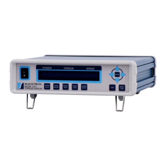
Page 15: Controls
2. Controls FRONT PANEL The front panel contains a Vacuum Fluorescent Display (VFD) that provides information about the control functions and torque transduce. Figure 2–1 Front Panel The buttons from left to right, top to bottom are: • POWER SWITCH •... - Page 16 • TM INVERT • RETURN When pressed takes the currently inputted torque reading and uses it as an offset value. The 3411 torque reading will now TARE display 0.0 when the torque value read is the same as when the TARE button was pressed.
-
Page 17: Rear Panel
Chapter 2 – Controls Magtrol Model 3411 Torque Display REAR PANEL The rear panel provides connectors and receptacles for connecting to appropriate equipment. Figure 2–2 Rear Panel 2.2.1 anel nPuts and utPuts Attach Ethernet cable here. -
Page 18: Figure 2-5 Transducer Connector
Magtrol Model 3411 Torque Display Chapter 2 – Controls Connect transducer signal cable here. TRANSDUCER 1. N/C 5 V COM 2. TACH B 3. +24 VDC TACH A 4. +24 VDC COM 5. +24 VDC COM BITE 6. N/C TORQUE COMMON 7. -
Page 19: Installation/Configuration
To make sure that the 3411 is operational, a Magtrol torque sensor must be installed and connected to the 3411. 1. Connect the 3411 to the torque transducer using a 14-pin to 6-pin signal cable. Figure 3–1 Cable and Connection Diagrams... -
Page 20: Default Display
SPEED FW REVXX FPGA REVXX Figure 3–3 Title Display 2 (5 seconds) 3.1.3 efauLt iSpLay When the 3411 is ready for use, the current power, torque and speed readings will appear on the display. POWER TORQUE SPEED +0.000 0.000 Figure 3–4 Default Display... -
Page 21: Manually Controlled Operation
4. Manually Controlled Operation SETTING DESIRED OPERATING PARAMETERS 4.1.1 orque caLe etup Select the Torque Scale. Press the TORQUE SCALE button. The display will appear as follows: POWER TORQUE SPEED Nm/5V XXXXXX Figure 4–1 Torque Scale Setup 2. Press the arrow buttons until desired torque scale appears in display. 3. -
Page 22: Power Units Setup
2. Press the UP/DOWN arrow buttons until desired power unit appears in display. 3. Press the ENTER button to save and return to the Default Display. 4.1.5 yStem etup Allows user to enter 3411’s system setup menu options. Submenus include: • BITE • USER SETUP •... -
Page 23: Figure 4-5 Bite Setup
When the transducer receives this signal it will output its full scale voltage value plus any offset value. The voltage the transducer outputs will show on the front panel of the 3411. The full scale output voltage for the TM series transducers is 5 volts, while the TF series will output 4 volts. -
Page 24: Figure 4-7 Ip Address View
Contrast The 3411 is shipped with the contrast programmed to the lowest setting in order to prolong display life. There are 3 levels of contrast, 1 is the lowest, 3 is the highest. If it is necessary to increase the contrast to improve readability, execute the following steps: 1. -
Page 25: Figure 4-9 Contrast Setup
Chapter 4 – Manually Controlled Operation Magtrol Model 3411 Torque Display POWER TORQUE SPEED Figure 4–9 Contrast Setup 4. Press the UP/DOWN arrow buttons until the desired contrast setting shows in the display. 5. Press ENTER to save and return to the Default Display. -
Page 26: Tare Button
Magtrol Model 3411 Torque Display Chapter 4 – Manually Controlled Operation 4.1.5.7 TM Invert Setup 1. Press the SYSTEM SETUP button. 2. Press the UP/DOWN arrow buttons until TM INVERT shows in the display. 3. Press ENTER to go to the TM invert setup menu. The display will appear as follows:... -
Page 27: Computer Controlled Operation
The 3411 can be interfaced to a personal computer using two different methods, USB and Ethernet. Through these two interfaces, there are two methods to control the 3411. One method is through a web interface, which is only available over Ethernet. The second method is a set of Mag.NET commands, which are fully described in the next chapter. - Page 28 If you have not installed one of these programs, this window will be displayed. 2. Obtain drivers install file torque3411.inf The drivers for the USB Communications Device Class (COM port) can be found on the Torque 7 installation disc included with your 3411. They can also be obtained from our webpage http://www.magtrol.com by following the download link located in the support menu tab.
- Page 29 Chapter 5 – Computer Controlled Operation Magtrol Model 3411 Torque Display 4. Open Windows Device Manager...
- Page 30 Magtrol Model 3411 Torque Display Chapter 5 – Computer Controlled Operation 5. Left click over the USB Communications Class Device 3411 device and select the update driver software option. 6. Select Browse my computer for driver software …...
- Page 31 Chapter 5 – Computer Controlled Operation Magtrol Model 3411 Torque Display 7. Select Let me pick from a list of device drivers on my computer... 8. Select Ports (COM &LPT) and click next...
- Page 32 Magtrol Model 3411 Torque Display Chapter 5 – Computer Controlled Operation 9. Select Have Disk… 10. Locate the torque3411.inf on your file system and select it to install.
- Page 33 Chapter 5 – Computer Controlled Operation Magtrol Model 3411 Torque Display 11. Choose Torque 3411 Serial Port and click Next... 12. Ignore the warning and click yes to continue installation.
-
Page 34: Connecting The 3411 Using Ethernet
IP ADDRESS VIEW option. (Refer to section 4.1.5.3 of the manual). If it is necessary that your 3411 use a static IP, you may use either the web interface or a set of Mag.NET commands to assign one. The web interface method is discussed in section 5.3.3, while the Mag.NET commands are... -
Page 35: Web Interface Operation
WEB INTERFACE OPERATION To access the web interface of the 3411, you must know the IP address of your unit. Once the units IP address is know, open a web browser on any computer in the same local network as your 3411 and type the units IP into the address bar. -
Page 36: Administration Settings
Magtrol Model 3411 Torque Display Chapter 5 – Computer Controlled Operation 5.3.2 dministRation ettings If desired, you may add security to protect access to the remote control panel. Just select a username and password and hit the “Turn Security On” button. This will prevent users from changing any of the unit’s settings, as well as prevent the viewing of all of the other pages. -
Page 37: Update Firmware
It is now possible to remotely update the 3411’s firmware via the web interface. Just select the update file and click the change firmware button. The “Change Firmware” button will not be enabled until a valid update file has been selected. Once the update process has completed the 3411 will reboot with the new version of the firmware installed. -
Page 38: Usb Test And Measurement Class Connection
You may use LabVIEW or any other programming language to write a custom program using sockets to open a connection to the 3411. The unit listens on port 3411 for any incoming connections. It is beyond the scope of this manual to discuss sockets programming, however, there are examples programs implementing this technique available on the Magtrol homepage. -
Page 39: Mag.net Commands
6. Mag.NET Commands The Mag.NET command set has been developed by Magtrol to communicate with our devices through a personal computer. All commands consist of ASCII text and are terminated by a carriage return line feed combination. In hex this is 0x0D 0x0A, or as part of a string they can be typed as “\r\n”. -
Page 40: Setup Commands
Magtrol Model 3411 Torque Display Chapter 6 – Mag.NET Commands SETUP COMMANDS Command Function Explanation Code Values for # are: 0 = None 4 = 20 Hz Sets filter 1 = 2 Hz 5 = 50 Hz 2 = 5 Hz... -
Page 41: Lan Setup Commands
Chapter 6 – Mag.NET Commands Magtrol Model 3411 Torque Display LAN SETUP COMMANDS Command Code Function Explanation DHCP# Enables/Disables DHCP use. Values for # are: You must send the “UPD” 1 = Enable command after sending 0 = Disable DHCP# for the change to take place. - Page 42 Magtrol Model 3411 Torque Display Chapter 6 – Mag.NET Commands Command Code Function Explanation Saves all LAN settings to non- To disable DHCP, the static ip, volatile memory and activates gateway, and netmask commands them. must have been given prior to sending “UPD”.
-
Page 43: Calibration And Miscellaneous Commands
Chapter 6 – Mag.NET Commands Magtrol Model 3411 Torque Display CALIBRATION AND MISCELLANEOUS COMMANDS Command Function Explanation Code Values for # MODE# User/Calibration mode 0 User 1 Calibration/engineering MODE 1 COMMANDS Caution calibration will be lost. *POWER cycle INIT Reset to factory defaults required after the command. -
Page 44: Output Binary Table
Magtrol Model 3411 Torque Display Chapter 6 – Mag.NET Commands OUTPUT BINARY TABLE Number Data Description Data Type TimeH Time stamp: the first 32 bit value Integer TimeL Time stamp: the last 32 bit value Integer Display speed Speed derived by using a 0.2 second... -
Page 45: Calibration
The 3411 features closed-box calibration. The advantage of closed-box calibration is that the user does not have to disassemble the case or make any mechanical adjustments to the 3411. The torque readout can be calibrated using external reference sources. Correction factors for offset and gain are stored in nonvolatile memory. -
Page 46: Speed Dac Calibration
Magtrol Model 3411 Torque Display Chapter 7 – Calibration caution et the filter Selection to none before Starting the calibration proceSS 1. Send the command MODE1 to the unit. 2. Send the command CAL to the unit. 3. The response will be ZERO VOLTS. - Page 47 Chapter 7 – Calibration Magtrol Model 3411 Torque Display 5. Send the command FREQ=XXXXXX.XX (where X.XXXX is your speed meter reading in Hz). 6. The response will be CAL COMPLETE. 7. Send the command MODE0 to the unit via USB.
-
Page 48: Theory
8. Theory FILTER PARAMETERS The digital filters of the 3411 are used to remove undesired noise from the TSC inputs. This noise could be conducted from electrical sources or mechanical vibrations. The input of the A/D converter internal to the 3411 has a traditional analog filter that is comprised of the following characteristics: •... -
Page 49: Troubleshooting
Check: • Baud rate Setup error and/or hardware No USB communication. • Cable attachment from fault. Torque Display to USB interface port of computer If you require additional assistance, please contact Magtrol Customer Service at 1-716-668-5555. -
Page 50: Appendix A: Schematics
Appendix A: Schematics 3411 SCHEMATIC... -
Page 51: Appendix B: Menu Structure
Appendix B: Menu Structure 3411 MENU STRUCTURE... - Page 52 Magtrol Model 3411 Torque Display Appendix B: Menu Structure...
-
Page 53: Appendix C: Computer Controlled Operation Prior To Firmware Version L
ABOUT THE ETHERNET INTERFACE Connect one side of the Ethernet cable to the 3411 RJ45 receptacle, and the other to a wall outlet, switch or router. Turn the power to the 3411 on; if already on, power cycle. Use the IP ADDRESS VIEW system setup option to discover the IP address assigned to your 3411. -
Page 54: Figure C-3 Network Settings Web Page
Magtrol Model 3411 Torque Display Appendix C: Computer Controlled Operation Press “Network”to display the LAN settings. Press key, to return to the home web page. Figure C–3 Network Settings web page In the home web page, press “TSP” to display the torque, speed and power web page. Select the “Periodic”... -
Page 55: About The Usb Interface
FoR indows indows Copy the 3411 USB driver files from the Torque 7 CD onto the local drive of your PC. The files are located in the \3411 DRIVER FOR WINDOWS\ folder on the CD. 1. Run CP210xVCPInstaller_x86.exe. 2. Power on the 3411. The Found New Hardware Wizard window will pop up as shown below. -
Page 56: Figure C-6 Installation Options Window
Magtrol Model 3411 Torque Display Appendix C: Computer Controlled Operation Figure C–6 Installation Options Window 4. Click the Next button. The following screen will display. The driver will be installed. Figure C–7 Installation Finish Window 5. Click Finish button, “Found new hardware” will show in right corner. Then USB driver has... -
Page 57: Usb Driver Setup For Windows7/8 64Bit
Copy the 3411 USB driver files from the Magtrol Manual CD at programs\3411USB Driver\ directory into local drive of your PC. 1. Run CP210xVCPInstaller_x64.exe. 2. Power on the 3411. A window in the right corner will show “Installing device driver software” and then show “Magtrol 3411 CP210x USB to UART Bridge(COM#)”. C.2.3... -
Page 58: Service Information
Magtrol, Inc. in the United States or Magtrol SA in Switzerland. Returning Equipment to Magtrol, Inc. (United States) When returning equipment to Magtrol, Inc.’s factory in the United States for repair and/or calibration, a completed Return Material Authorization (RMA) form is required. - Page 59 Testing, Measurement and Control of Torque-Speed-Power • Load-Force-Weight • Tension • Displacement www.magtrol.com MAGTROL INC MAGTROL SA Subsidiaries in: 70 Gardenville Parkway Route de Montena 77 Germany • France China • India Buffalo, New York 14224 USA 1728 Rossens / Fribourg, Switzerland...
Need help?
Do you have a question about the 3411 and is the answer not in the manual?
Questions and answers