Table of Contents
Advertisement
Quick Links
Advertisement
Table of Contents

Related Manuals for Freetech P6F209


Summary of Contents for Freetech P6F209
- Page 1 2$. ' MOTHER BOARD USER’S MANUAL...
- Page 2 Copyright Notice © Copyright 2001 The information contained in this user’ s manualand all accompa- nying documentation is copyrighted and all rights are reserved. This publication may not, in whole or in part, be reproduced, transcribed, stored in a retrieval system, translated into any language or computer language, or transmitted in any form whatsoever without the prior written consent from the manufac- turer, except for copies retained by the purchasers for their...
- Page 3 Using This Manual This manual is designed to help you build a reliable Personal Computer based on the P6F209 platform. Chapter 1 - Quick Reference This chapter is for advanced users who want to quickly assemble a system. The mainboard layout along with jumper and switch settings, and memory configuration are provided.
-
Page 4: Table Of Contents
Table of Contents 1. P6F209 QUICK REFERENCE ..........1 1.1. Mainboard Layout ............1 1.2. I/O Ports ................2 1.3. Front Panel Connector ............. 2 1.4. Jumpers ................3 1.5. PCI and AGP Frequency Settings ........3 1.6. Memory Installation ............3 1.7. Connectors ............... 4 2. - Page 5 3.5.4. LAN LED Connector (J16) ..........18 3.5.5. Audio Mic-In and Line-In Connectors (JP5) ....18 3.5.6. Serial COM2 Connectors (JP6) ........19 3.5.7. Front USB Connectors (J15) ..........19 3.5.8. AMR Connector (JP8) ............20 3.5.9. Floppy Drive Connector (J13) .......... 20 3.5.10.
- Page 6 4.10. Load Optimized Defaults Option ........60 4.11. Set Supervisor/User Password ........60 4.12. Save & Exit Setup ............61 4.13. Exit Without Saving ............61 5. DRIVER AND UTILITY ............62 5.1. Flash Utility ..............62 CD Driver Overview............63 5.2.1. VIA 4 In 1 Driver ............. 64 5.2.2.
-
Page 7: P6F209 Quick Reference
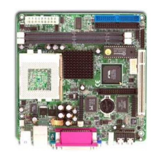
1. P6F209 Quick Reference This section is for users to get started using the mainboard straight away. 1.1. Mainboard Layout VGA PORT, SE RIAL PO RT & MIC-IN LINE-O UT 1394 PARALL EL POR PS /2 MOUSE & PO RT... -
Page 8: I/O Ports
Mainboard User’s Manual 1.2. I/O Ports Par allel p ort L A N po rt PS /2 M o us e po rt IEE E-13 9 C o nn ect or L in e-O ut M IC -In U SB p o rts PS /2 K ey bo ard po VG A p or t C O M 1 po rt... -
Page 9: Jumpers
P6F209 Quick Reference 1.4 Jumpers Clear CMOS Normal Mode 1.5. PCI and AGP Frequency Setting The PCI and AGP frequency settings are automatically set by the system 1.6. Memory Installation Note: The S3 PL133 chipset family used in this mainboard supports up to two double-sided or three single-sided DIMMs when the DRAM interface is operating at 133 MHz. -
Page 10: Connectors
Mainboard User’s Manual 1.7. Connectors FAN1 CPU/Chipset FAN Connector This 3-pin header is (J1) used for connecting a CPU chipset fan. FAN2 System Fan Connector This 3-pin header is for (J17) connecting the case fan that keeps the system cool. 1394 Connector This 6-pin header is used for connecting a 1394 devices. -
Page 11: Introduction
The high quality P6F209 is a high performance, enhanced function mainboard that supports 64-bit Intel FC-PGA and Pentium III/Cyrix Socket 370 processors. The P6F209 is based on the VIA S3 PL133 chipset. Intel delivers superior high performance with all the innovative features and proven reliability of the VIA S3 PL133 chipset family. -
Page 12: Mainboard Specifications And Features
Mainboard User’s Manual 2.2. Mainboard Specifications and Features 2.2.1. Hardware ® ® Intel FC-PGA, Pentium III and Cyrix Socket 370 Processors or other compatible Auto-detection Onboard Voltage Regulator Module Provides 1.3V to 3.5V operating voltage Coprocessor CPU has built-in floating point unit Speed System bus clock 66/100/133 MHz PCI bus clock 33 MHz... -
Page 13: Software
Introduction Expansion One 32-bit PCI slot Slots One Digital Video ouptup header One AMR header Compliant with EPA, APM 1.2 and ACPI Power Management Auto Power on ATX soft-off power control Power – on by keyboard and PS/2 mouse Power – on by external modem ring Power –... -
Page 14: Environment
Mainboard User’s Manual Driver and VIA 4 in 1 driver Utility VIA ProSavage Display driver AC97 codec audio driver LAN driver Flash utility for BIOS upgrade System Environment Monitoring Utility Operating Operates with MS_DOS, Windows 3.x/9x/ME/XP/ System 2000/NT, OS/2, Novell NetWare/UnixWare 1.1, and SCO Unix 4.2 2.2.3. -
Page 15: Mainboard Layout
Introduction 2.3. Mainboard Layout VG A PO RT, SERIAL PO R T & MIC -IN L IN E-O UT 13 9 PA RA LL EL PO R T PS/2 M O USE & PO RT PO RT PO RT L AN & PS/2 K EYBO A RD PO R TS U SB 1 PO RT S "... - Page 16 Mainboard User’s Manual Key to Mainboard Components Name Function PGA370 CPU socket JWR1 ATX power connector DIMM1~2 Memory module slots Floppy drive connector IDE0 IDE 0 connector (blue) IDE1 IDE 1 connector (white) Digital Vidio output port PCI1 32-bit PCI slot 6-pin 1394 header COM2 connector AMR header...
-
Page 17: Microprocessor
Introduction 2.4. Microprocessor The mainboard is designed to operate with the following processors: Processor Type Intel FC-PGA Cel e ron 66/100 MHz Intel FC-PGA Pentium III 100/133 MHz VIA Cyrix C3 100/133 MHz An onboard switching voltage regulator provides the required 1.3 to 3.5 volts for the processor. -
Page 18: Chipset
Mainboard User’s Manual 2.6. Chipset The P6F209 supports the VIA S3 PL133 chipset. The VIA S3 PL133 chipset is designed for desktops and workstations that provide internal or external graphics, and provides ATA-100 and SDRAM support. The VT82C686B I/O controller hub makes a direct connection between the graphics system, the IDE controller, and the PCI bus. -
Page 19: Hardware Installation
Of course, you can use the system I/O ports and expansion slots to add many more features and components to your system than the items listed above. 3.1. Unpacking The P6F209 mainboard package contains the following items: One mainboard One IDE 66/100 40-pin ribbon cable One floppy 34-pin ribbon cable Driver and utility CD User’s manual reference... -
Page 20: Installation
Mainboard User’s Manual 3.2. Installation The P6F209 is designed to fit into a standard FATX form factor chassis. The pattern of the mounting holes and the position of the back panel connectors meet the FATX system board specification. The chassis comes with various mounting fasteners, which are made of metal or plastic. -
Page 21: Connector/Jumper Location
Hardware Installation 3.4. Connector/Jumper Location VG A PO R T, SER IA L PO R T & M IC -IN L IN E-O U T 13 9 PA R AL L EL PO RT PS/2 MO U SE & PO R T PO R T PO R T L AN &... -
Page 22: Attaching Connectors
Mainboard User’s Manual 3.5. Attaching Connectors 3.5.1. Front Panel Connectors (JP9) There are seven connectors on the mainboard for speaker, switches, and indicator lights on the system’s front panel. G r ou nd + 5V (PWRO N) JP 7 JP 3 POWER SWITCH G r ou nd P o we r on/ of... -
Page 23: Audio Cd-In Connector (Jp7)
Hardware Installation 3.5.2. Audio CD-In Connector (JP7) This connector enable you to connect a CD-ROM to the mainboard and receive stereo audio input. JP 7 JP 3 C D- I N JP 5 M I C & LI N E- I N LI N E- O U T LA N L ED A UD I O C O DE C... -
Page 24: Lan Led Connector (J16)
Mainboard User’s Manual 3.5.4. LAN LED Connector (J16) Connect on set of 3-pin of LAN LED cable to LAN LED header, when detecting the outside signal, the LED head would be light, and the light will besparkle during the transferring data. JP 7 JP 3 C D- I N... -
Page 25: Serial Com2 Connectors (Jp6)
Hardware Installation 3.5.6. Serial COM2 Connector (JP6) The mainboard provides one onboard serial COM2 connector. The COM2 connector on the same signal with COM1 on the back panel. JP 7 JP 3 C D- I N JP 5 M I C & LI N E- I N LI N E- O U T LA N L ED A UD I O C O DE C... -
Page 26: Amr Connector (Jp8)
Mainboard User’s Manual 3.5.8. AMR Header (JP8) The AMR headers Supports the Audio and modem function. Pin 1 JP 7 JP 3 C D- I N JP 5 M I C & LI N E- I N LI N E- O U T LA N L ED A UD I O C OD E C 13 94 C O... -
Page 27: 1394 Header (Jp4)
Hardware Installation 3.5.10. 1394 Header (JP4) This 6-pin header enable you to connect a 1394 device on the 1394 header. JP 7 JP 3 C D- I N JP 5 M I C & LI N E- I N LI N E- O U T LA N L ED A UD I O C O DE C 13 94 C O... -
Page 28: Ide Connectors
Mainboard User’s Manual 3.5.12. IDE Connectors An IDE drive ribbon cable has two connectors to support two IDE drives. If a ribbon cable connects to two IDE drives at the same time, one of them has to be configured as Master and the other has to be configured as Slave by setting the drive select jumpers on the drive. -
Page 29: Back Panel Connectors
Hardware Installation 3.5.13. Back Panel Connectors The back panel provides external access to PS/2 style keyboard and mouse connectors, one serial port, one VGA port, one parallel port, dual USB ports, one LAN port, one 1394 port, and audio Line-out, Mic-in port which are integrated on the mainboard. - Page 30 Mainboard User’s Manual LAN Port Connect a device to the LAN port on the back panel. L A N po rt Parallel Port Connect a printer or other parallel device to the burgundy-colored 25-pin parallel port. You can set the parallel port IRQ and parallel port mode in BIOS.
- Page 31 Hardware Installation C O M 1 po rt Note: Serial printers must be connected to the serial port. 1394 Port Connector You can connect 1394 devices to 1394 port on the back panel. 13 94 por Audio Line-Out Port Connectors You can connect various audio devices to this audio jacks.
-
Page 32: Power Supply Connector (Jwr1)
Mainboard User’s Manual 3.5.14. Power Supply Connector (JWR1) The ATX power supply has a single lead connector with a clip on one side of the plastic housing. There is only one way to plug the lead into the ATX power connector. Press the lead connector down until the clip snaps into place and secures the lead onto the connector. -
Page 33: Cpu/System Fan Power Supplies
Hardware Installation 3.5.15. CPU/System Fan Power Supplies FAN1(J1) / FAN2(J17) There are two fan connectors on the mainboard for the cooling fans. The connectors support fans of 12V DC/500mAMP (six watt) or less. When the system goes into sleep state, fans should be shut down to eliminate audible noise and reduce power consumption. -
Page 34: Pci Connector (Pci1)
Mainboard User’s Manual 3.5.16. PCI Connector (PCI1) PCI connector is one of equipment interfaces that connects pheripheral equipment and motherboard. Its transfer speed is faster than traditional ISA. PCI is the mainstream transfer interface for extra adopter. Pin 1 JP 7 JP 3 C D- I N JP 5... -
Page 35: Installing The Cpu
Hardware Installation 3.6. Installing the CPU 3.6.1. Before You Begin 1. Be sure that your processor kit includes the following items: One processor with the fan or heat sink attached One power cable (for CPU with cooling fan attached) 2. Place the mainboard on a workbench (not in a chassis). Be sure that the mainboard is empty (that is, no DIMMs, cables, or cards are installed) and that the holes for the fan or heat sink support pegs are empty. -
Page 36: Removing The Processor
Mainboard User’s Manual processor should drop into place without any force. If it doesn’t seat properly, check that you have the pin-1 corner in the correct position. S o c k e t L e v e r CP U P ro ce s so r P in- 1 6. -
Page 37: Installing System Memory
Hardware Installation 3.6.4. Installing System Memory Maximum system memory supported by the mainboard is 1 GB. The mainboard has two DIMM Sockets. Memory can be installed using 168-pin SDRAM DIMM memory modules. There are no jumper settings required for the memory size or type, which is automatically detected by the BIOS. - Page 38 Mainboard User’s Manual Due to the high-speed design of the mainboard, the memory modules must meet the following requirements: DRAM TYPE SDRAM (Syn chro nous DRAM Module Size Single Sided Asymmetric 1Mx64, 4Mx64, 8Mx64, 16Mx64 Double-Sided Asymmetric 2Mx64, 4Mx64, 8Mx64, 16Mx64, 32Mx64 Requirements SDRAM Extended Data Out pu...
-
Page 39: Setting Jumpers
Hardware Installation 3.6.5. Setting Jumpers Refer to the following illustration and instructions to set the jumpers on your mainboard. JP 7 JP 3 C D- I N JP 5 M I C & LI N E- I N LI N E- O U T LA N L ED A UD I O C O DE C 13 94 C O... -
Page 40: Auto Power On
Mainboard User’s Manual Note: If you are unable to enter BIOS setup, turn the system on and off a few times. 3.6.6. Auto Power On After losing AC power, the system will not turn on automatically when the power comes back unless you set the options in BIOS. This concludes Chapter 3. -
Page 41: Bios Configuration
4. BIOS Configuration After the hardware configuration of the mainboard is finished, and the system hardware has been assembled, the system may be powered up. At this point, CMOS setup should be run to ensure that system information is correct. The mainboard employs the latest Award BIOS CMOS chip with support for Windows Plug and Play. -
Page 42: Entering Setup
Mainboard User’s Manual This program should be executed under the following conditions: K When changing the system configuration K When a configuration error is detected by the system and you are prompted to make changes to the Setup program K When resetting the system clock K When setting the CPU clock speed so that it automatically runs either fast or slow K When redefining the communication ports to prevent any conflicts... - Page 43 BIOS Configuration “Press DEL to enter SETUP” To access the AWARD BIOS SETUP program, press the <DEL> key to display the “CMOS SETUP UTILITY” screen: These screens provide access to the utility’s various functions. Listed below are explanations of the keys displayed at the bottom of the screen: Function Escape key: Exits the current menu...
-
Page 44: Standard Cmos Features
Mainboard User’s Manual 4.2. Standard CMOS Features Standard CMOS Features is the same for all three chipsets. Selecting “Standard CMOS Features” on the main program screen displays the following menu: The Standard CMOS Setup utility is similar for all three chipsets and is used to configure the following features: Date: Month, Day, Year Time: Hour, Minute, and Second. - Page 45 BIOS Configuration If the auto-detected parameters displayed do not match the ones that should be used for your hard drive, do not accept them. Press the <N> key to reject the values and enter the correct ones manually in the Standard CMOS Setup screen. Note: If you are setting up a new hard disk drive that supports LBA mode, more than one line will appear in the param eter box.
- Page 46 Mainboard User’s Manual Video: Set this field to the type of graphics card installed in your system. If you are using a VGA or higher resolution card, choose the “EGA/ VGA” option. The options are: H EGA/VGA (default) H MONO H CGA 40 H CGA 80 Halt On: This setting determines which type of errors will cause the...
-
Page 47: Advanced Bios Features
BIOS Configuration 4.3. Advanced BIOS Features Selecting “Advanced BIOS Features” on the main program screen displays this menu, which allows you to define advanced information about your system. You can make modifications to most of these items without introducing fatal errors to your system. Note that the page has a scroll-bar to scroll down to more items. - Page 48 Mainboard User’s Manual Processor Number Feature: Some new processors are installed with a unique processor number. This unmber may be used for verification in Internet transactions and ecommerce. If you prefer not to use or distribute the unique processor number, set this item to Disabled to suppress the processor number.
- Page 49 BIOS Configuration Security Option: This setting controls the password feature. The options are “Setup” and “System.” Selecting “Setup” will protect the configuration settings from being tampered with. Select “System” if you want to use the password feature every time the system boots up. The default setting is “Setup.”...
-
Page 50: Advanced Chipset Features
Mainboard User’s Manual 4.4. Advanced Chipset Features Selecting “Advanced Chipset Features” on the main program screen displays this menu: This screen controls the settings for the board’s chipset. All entries related to the DRAM timing on the screen are automatically configured. Do not make any changes unless you are familiar with the chipset. - Page 51 BIOS Configuration Memory Hole: In order to improve performance, some space in memory can be reserved for ISA cards. The default setting is “Disabled.” P2C/C2P Concurrency: This item allows you to enable/disable the PCI to CPU and CPU to PCI concurrently. The default setting is “Enabled.” System BIOS Cacheable: When set to “Enabled”, the System BIOS will be cached for faster execution.
- Page 52 Mainboard User’s Manual USB Mouse Support: Enabled (default) this function when a USB mouse is used. Set to “Disabled” when an PS/2 mouse is being used. On Chip Sound: This item allows you to control the onboard AC 97 audio. The default setting is “Auto.” On Chip Modem: This item allows you to control the onboard MC 97 Modem.
-
Page 53: Integrated Peripherals
BIOS Configuration 4.5. Integrated Peripherals Selecting “Integrated Peripherals” on the main program screen displays this menu: OnChip IDE Channel0: The chipset contains a PCI IDE interface with support to two IDE chan-nels. Select Enabled to activate the primary IDE interface; select Disabled to deactivate this interface. The default settings are “Enabled.”... - Page 54 Mainboard User’s Manual H Auto (default) H Mode 0 H Mode 1 H Mode 2 H Mode 3 H Mode 4 IDE Primary/Secondary Master/Slave UDMA: When set to “Auto” the BIOS will automatically load the Ultra DMA 33 driver to match the transfer rate of IDE hard disk drives that support Ultra DMA 33 mode.
- Page 55 BIOS Configuration IR Function Duplex: This item allows you to select the IR half/full duplex funcion. The default setting is “Half.” TX, RX inverting enable: This item allows you to enable the TX, RX in- verting which depends on different H/W requirement. This field is not rec- ommended to change its default setting for avoiding any error in your sys- tem.
- Page 56 Mainboard User’s Manual SB DMA Select: This item selects the Sound Blaster DMA. The default setting is “DMA 1.” MPU-401: This item enables/disables on-board MPU-401. The default setting is “Disabled.” MPU-401 I/O Address: This item selects MPU-401 I/O Address. The default setting is “330-333H..”...
-
Page 57: Power Management Setup
BIOS Configuration 4.6. Power Management Setup Power Management Setup controls the mainboard’s “Green” features. Selecting “Power Management Setup” on the main program screen displays this menu: ACPI Function: When set to “Enabled,” turns on the ACPI Function. The default setting is “Enabled.” Note: ACPI (Advanced Configuration and Power Interface) is a power management specification that makes hardware status informa- tion available to the operating system. - Page 58 Mainboard User’s Manual HDD Power Down: The IDE hard drive will spin down if it is not accessed within a specified length of time. Options are from “1 Min” to “15 Min” and “Disable.” The default is “Disabled.” Doze Mode: When this item enabled and after the set up time of system inactivity, the CPU clock will run at a lower speed while all other devices still operate at full speed.
- Page 59 BIOS Configuration Video Off Method: This setting controls the video off method in power saving mode. The “DPMS” option allows the BIOS to control the video card if it has the DPMS (Display Power Management System) feature. Other options are “V/H SYNC+Blank” (default) and “Blank Screen.” The “V/H SYNC+Blank”...
- Page 60 Mainboard User’s Manual Wake Up Events: This item enables a user to select wake up events. Press "Enter" to choose whether a specified event can wake up a system from suspend mode or not ; events include "VGA", "LPT &COM", "HDD &...
- Page 61 BIOS Configuration Primary INTR: Press Enter to on/off the wake up ability of a speci- fied IRQ. In the following is a list of IRQ's, Interrupt ReQuests, which can be exempted much as the COM ports and LPT ports above can. When an I/O device wants to gain the attention of the operating system, it signals this by causing an IRQ to occur.
-
Page 62: Pnp/Pci Configurations
Mainboard User’s Manual 4.7. PnP/PCI Configurations Both the ISA and PCI buses on the Mainboard use system IRQs (In- terrupt ReQuests) and DMAs (Direct Memory Access). You must set up the IRQ and DMA assignments correctly through the PnP/PCI Configura- tion Setup utility;... - Page 63 BIOS Configuration IRQ/DMA Resources: When resources are controlled manually, assign each system interrupt a type, depending on the type of device using the interrupt. IRQ3/4/5/7/9/10/11/12/14/15 assigned to: This item allows you to determine the IRQ assigned to the ISA bus and is not available to any PCI slot.
-
Page 64: Pc Health Status Option
Mainboard User’s Manual 4.8. PC Health Status On mainboards that support hardware monitoring, this item lets you monitor the parameters for critical voltages, critical temperatures, and fan speeds. Selecting “PC Health Status” on the main program screen displays this menu: System Component Characteristics: These fields provide you with information about the systems current operating status. -
Page 65: Frequency/Voltage Control
BIOS Configuration 4.9. Frequency/Voltage Control This item enables you to set the clock speed and system bus for your system. The clock speed and system bus are determined by the kind of processor you have installed in your system. Auto Detect DIMM/PCI Clk: When set to “Enabled” (default), the system will automatically turn off the PCI and DIMM clock when not in use to reduce electromagnetic interference. -
Page 66: Load Optimized Defaults Option
Mainboard User’s Manual 4.10. Load Optimized Defaults Option This option opens a dialog box that lets you install optimized defaults for all appropriate items in the whole Setup Utility. Press the <Y> key and then <Enter> to install the defaults. Press the <N>... -
Page 67: Save & Exit Setup
BIOS Configuration 4.12. Save & Exit Setup Selecting this option and pressing <Enter> will save the new setting information in the CMOS memory and continue with the booting process. 4.13. Exit Without Saving Selecting this option and pressing <Enter> will exit the Setup Utility without recording any new values or changing old ones. -
Page 68: Driver And Utility
5. Driver and Utility 5.1. Flash Utility The BIOS of the P6F209 mainboard can be upgraded by using a Flash utility. A new version of the BIOS can be downloaded from the factory’s BBS and Web site. The system BIOS is stored in a 1 M-bit Flash EEPROM that can be erased and reprogrammed by the Flash utility. -
Page 69: Cd Driver Overview
CD AutoRun screen should appear. If the AutoRun screen does not appear, duble click or run D:\ Autorun.exe (assuming that your CD-ROM drive is drive D:) The P6F209 CD include 1. Install Mainboard Software (VIA) 2. Install display device driver (ProSavage) 3. -
Page 70: Via 4 In 1 Driver
Mainboard User’s Manual 5.2.1. VIA 4 In 1 driver This folder has 4 in 1drivers for Windows Millennium/2000/98/95/NT. The Installation Steps: 1. Insert the manufacturer’s CD-ROM into your CD-ROM drive. 2. Click Driver Install. 3. Select the folder Driver\Via\4in1driver for WIN2000/9X/ ME or NT to start the installation: 4. -
Page 71: Ac97 Audio Driver
Driver and Utility 5.2.3. AC97 Audio Driver Software and drivers are provided for the VT82C686B codec sound system that is integrated on this mainboard. The VT82C686B codec allows the system to generate optimal sound effects. Drivers are provided for Windows NT/2000/98SE/95/NT. The manual Installation Steps: 1.
Need help?
Do you have a question about the P6F209 and is the answer not in the manual?
Questions and answers