Table of Contents
Advertisement
Quick Links
Advertisement
Table of Contents

Related Manuals for Freetech P6F163


Summary of Contents for Freetech P6F163
- Page 1 P6F163 MOTHER BOARD USER’S MANUAL Ver 1. JUL.3.2003...
- Page 3 Copyright Notice ©Copyright 2000 The information contained in this user’s manual and all accompanying documentation is copyrighted and all rights are reserved. This publication may not, in whole or in part, be reproduced, transcribed, stored in a retrieval system, translated into any language or computer language, or transmitted in any form whatsoever without the prior written consent from the manufacturer, except for copies retained by the purchasers for their personal...
- Page 4 Perface Using This Manual This manual is designed to help you build a reliable Personal Computer based on the P6F163 platform. Chapter 1—Quick Reference This chapter is for advanced users who want to quickly assemble a system. The mainboard layout along with jumper and switch settings, and memory configuration are provided.
-
Page 5: Table Of Contents
Perface Table of Contents 1. P6F163 QUICK REFERENCE..........1.1. Mainboard Layout .............. 1.2. Back I/O Ports..............1.3. Front I/O Ports ..............1.4. Jumpers ................1.5. Extended Connector Board ..........1.6. PCI Frequency Settings............. 1.7. Memory Installation............1.8. Connectors................. 2. INTRODUCTION .............. - Page 6 Perface 3.5.1. Audio CD-In Connector (CD1) ..........3.5.2. Audio AUX-IN Connector (AUX1)........ 3.5.3. IDE Connectors..............3.5.4. PCI Connector (PCI)..............3.5.5. Serial COM2 Connector (COM2)........ 3.5.6. CON2 Connector (CON2)............3.5.7. TV-Out Connector (Optional) ............ 3.5.8. 1394 Connector (1394) ..............3.5.9. Front Mic-IN, Line-IN Connector........ 3.5.10.
- Page 7 Perface 4.7. PnP/PCI Configurations........... 4.8. PC Health Status Option ..........4.9. Frequency/Voltage Control..........4.10. Load Fail-Safe Defaults Option..........4.11. Load Optimized Defaults Option ........ 4.12. Set Supervisor/User Password ........4.13. Save & Exit Setup ............4.14. Exit Without Saving............5. DRIVER AND UTILITY............5.1.
-
Page 9: P6F163 Quick Reference
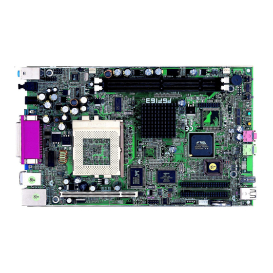
1. P6F163 Quick Reference This section is for users to get started using the mainboard straight away. 1.1. Mainboard Layout PGA370 CPU socket (PGA370) AUDIO connector (CD IN) DIMM module sockets (DIMM1~2) AUDIO connector (AUX) IDE connector (IDE1) CPU FAN... -
Page 10: Back I/O Ports
Mainboard User’s Manual 1.2. Back I/O Ports 1.3. Front I/O Ports 1.4. Jumpers For 133 MHz FSB CPU (CPU Selector) For 100 MHz FSB CPU Clear CMOS (CMOS Clear) Normal Mode Back I/O Port... -
Page 11: Extended Connector Board
Mainboard User’s Manual 1.5. Extended Connector Board 1.6. PCI Frequency Setting The PCI frequency settings are automatically set by the system 1.7. Memory Installation Note: The S3 PL133 chipset family used in this mainboard supports up to two double-sided or three single-sided DIMMs when the DRAM interface is operating at 133 MHz. -
Page 12: Connectors
Mainboard User’s Manual 1.8. Connectors 1394 1394 connector Auxiliary-IN connector : This 4-pin header is an auxiliary input connector. CD-IN connector : This 4-pin header is used for CD IN connecting the CD ROM audio input to the sound card. CPU FAN This 3-pin header is used for connecting a CPU fan. -
Page 13: Introduction
Intel ® mainboard that supports Pentium III/Cyrix-III Socket 370 processors. The P6F163 is base on the VIA S3 PL133 chipset. VIA delivers superior high performance with all the innovative feature and proven reliability of the VIA S3 PL133 chipset family. Pin-to-pin compatible with the VIA S3 PL133 chipset. -
Page 14: Mainboard Specifications And Features
Mainboard User’s Manual 2.2. Mainboard Specifications and Features 2.2.1. Hardware Intel ® FC-PGA, FC-PGA2 Pentium ® III and Cyrix Socket 370 Processors or other compatible Auto-detection CPU Onboard Voltage Regulator Module Provides 1.3V to 3.5V operating voltage Coprocessor CPU has built-in floating point unit Speed System bus clock 66/100/133 MHz PCI bus clock 33 MHz... - Page 15 Introduction Sound Chip Chip integrated direct Sound AC97 2.2 interface. Realtek ALC201A On-Board TV out Realtek 8100 LAN chipset, supports 10/100 & LAN Mb/s TV-out with 1024×768 input video resolution. (optional) I/O Options One connector for front panel USB ports 3/4 One line-out, mic-in, LAN, VGA, 1394 on board Two COM ports by cable...
-
Page 16: Software
Mainboard User’s Manual 2.2.2. Software BIOS AWARD AGP/PCI BIOS 2M-bit Flash BIOS with ESCD (Extended System Configuration Data) block Supports APM, Plug and Play, Multi-Boot, DMI and EIDE devices Supports ACPI Supports high-capacity LS-120 and ZIP removable media drive Driver and IDE Bus mastering Ultra DMA driver Utility AC97 codec audio driver... -
Page 17: Mainboard Layout
Introduction 2.3. Mainboard Layout Note: Because of optional items and design changes, your mainboard may not be identical to the one shown in the illustration. Mainboard Layout... - Page 18 Mainboard User’s Manual Key to Mainboard Components Name Function PGA370 CPU socket DIMM1~2 SDRAM Memory module slots IDE1 IDE 1 connector IDE2 IDE 2 connector 32-bit PCI Slot TV-Out TV-Out connector COM2 COM2 connector 1394 1394 connector HDD & CD-ROM Power Connector Audio Front Mic-in, Line-in connector Audio...
-
Page 19: Microprocessor
Introduction 2.4. Microprocessor The mainboard is designed to operate with the following processor: Processor Type Intel FC-PGA Celeron 66/100 MHz Intel FC-PGA, FC-PGA2 Pentium III 100/133 MHz VIA Cyrix C3 100/133 MHz An onboard switching voltage regulator provides the required 1.3 to 3.5 volts for the processor. -
Page 20: Chipset
Mainboard User’s Manual 2.7. Chipset The P6F163 supports the VIA S3 PL133 chipset. The VIA S3 PL133chipset is designed for desktop and workstation that provide internal or ext ernal graphics, and provides ATA -100 and SDRAM supports. The VT82C686B I/O controller hub makes a direct connection between the graphics system, the IDE controller, and the PCI bus. -
Page 21: Hardware Installation
One 1394 Two S_ATA (optional) One LAN / Modem One set of loudspeakers Four USB 3.1. Unpacking The P6F163 mainboard package contains the following items: One mainboard One AC adapter Constitute sketch Driver and utility CD User’s manual After removing the mainboard from its anti-static bag, place it on a grounded or antistatic surface (component side up). -
Page 22: Installation
Mainboard User’s Manual 3.2. Installation The P6F163 is designed to fit into a special ATX form factor chassis. The chassis comes with various mounting fasteners, which are made of metal or plastic. It is highly recommended to use as many metal fasteners as possible to mount the mainboard in the chassis for better grounding. -
Page 23: Connector/Jumper Location
Hardware Installation 3.4. Connector/Jumper Location Connector/Jumper Location... -
Page 24: Attaching Connectors
Mainboard User’s Manual 3.5. Attaching Connectors 3.5.1. Audio CD-In Connector (CD IN) This connector enables you to connect a CD-ROM to the mainboard and receive stereo audio input. 3.5.2. Audio AUX-IN Connectors (AUX) This connector enables you to connect a stereo audio input from CD-ROM, TV-tuner, or MPEG card. -
Page 25: Ide Connectors
Hardware Installation 3.5.3. IDE Connectors Connect the slim HDD to slim HDD connector in extended connector board and connect the slim CD-ROM to slim CD-ROM connector. 3.5.4. PCI Connector (PCI) PCI connector is one of equipment interfaces that connect peripheral equipment and motherboard. -
Page 26: Serial Com2 Connector (Com2)
Mainboard User’s Manual 3.5.5. Serial COM2 Connector (COM2) The mainboard provides one onboard serial COM2 connector. The COM2 connector has the same signal with COM1 on the back panel. 3.5.6. CON2 Connector (CON2) CON2 is IDE connector. Connect “Extended Connector Board”. Attaching Connector... -
Page 27: Tv-Out Connector (Optional)
Hardware Installation 3.5.7. TV-Out Connector (Optional) Connect the cable attached from this connector to TV-Out. 3.5.8. 1394 Connector Connect the cable attached to 1394 connector on front panel. Attaching Connector... -
Page 28: Front Mic-In, Line-In Connector
Mainboard User’s Manual 3.5.9. Front Mic-IN, Line-IN Connector Connect a tape player or another audio source to the light blue Line-in connector to record audio on your computer or to play audio through your computer’s sound chip and speaker. Connect a microphone to the pink microphone connector to record audio to your computer. -
Page 29: Hdd & Cd-Rom Power Connector
Hardware Installation 3.5.11. HDD & CD-ROM Power Connector Connect 15cm power cable attached from this connector to HDD or CD-ROM. 3.5.12. CPU / System Fan Power Supplies There are three fan connectors on the mainboard for the cooling fans. The connectors support fans of 12VDC/500mAMP (six watt) or less. When the system goes into sleep state, fans should be shut down to eliminate audible noise and reduce power consumption. -
Page 30: Back I/O Port
Mainboard User’s Manual 3.5.13. Back I/O Port The back panel provides external access to PS/2 style keyboard and mouse connectors, one serial port, one parallel port, one S/PDIF port, VIN_12V port, one VGA port, one LAN port, dual USB ports, and audio Line-out, Line-in, Mic-in, ports which are integrated on the mainboard. - Page 31 Hardware Installation Audio Mic-In Port You can connect a microphone to the pink microphone connector to record audio to your computer. S/PDIF Port You can connect S/PDIF device to the black connector to your computer. S/PDIF (Sony / Philips Digital Interface) is a standard audio transfer file format.
- Page 32 Mainboard User’s Manual Parallel Port Connect a printer or other parallel device to the burgundy-colored 25-pin parallel port. You can set the parallel port IRQ and parallel port mode in BIOS. Refer to Integrated Peripherals in Chapter 4 for details. Serial Port Connect a serial device such as a mouse or modem to the 9-pin serial port.
- Page 33 Hardware Installation PS/2 Mouse and PS/2 Key board Ports Connect a PS/2 mouse to the green 6-pin mini DIN connector. The system will automatically assign IRQ 12 to the PS/2 mouse if one is connected. Connect a PS/2 keyboard to the purple 6-pin mini DIN connector. If you want to connect a standard AT size (large DIN) connector, you must use and adapter.
-
Page 34: Front I/O Port
Mainboard User’s Manual LAN Port Connect a device to the LAN port on the back panel. 3.5.14. Front I/O Port The Front panel provides two USB ports, one 1394 port, one S_ATA port, one earphone port, one MIC port. The figure below shows the location of the front panel connectors. - Page 35 Hardware Installation S_ATA Port (Optional) Connect a device to the S_ATA port on the front panel. Serial ATA is the latest ATA transmission interface, developed for multi-purposes, including fast data transmission, user-friendly interface, self-adjusting capability, and above all, it must be compatible with the Parallel ATA software. Internal storage devices are serial ATA target in the market.
-
Page 36: Installing The Cpu
Mainboard User’s Manual 3.6. Installing the CPU 3.6.1. Before You Begin Be sure that your processor kit includes the following items: One processor with the fan or heat sink attached One power cable (for CPU with cooling fan attached) Place the mainboard on a workbench (not in a chassis). Be sure that the mainboard is empty (that is, no DIMMs, cables, or cards are installed) and that the holes for the fan or heat sink support pegs are empty. -
Page 37: Removing The Processor
Hardware Installation Identify the pin-1 corner of the PGA370. The pin-1 corner is on the same side as the locking lever, as shown in the illustration below. Identify the pin-1 corner of the processor (the pin-1 corner on the processor has a beveled edge). Align the pin-1 corners and drop the processor into the mPGA370. -
Page 38: Installing System Memory
Mainboard User’s Manual 3.7. Installing System Memory Maximum system memory supported by the mainboard is 1GB. The mainboard has two DIMM Sockets. Memory can be installed using 184-pin DDR SDRAM DIMM memory modules. These are no jumper settings required for the memory size or type, which is automatically detected by the BIOS. -
Page 39: Setting Jumpers
Hardware Installation 3.8. Setting Jumpers Refer to the following illustration and instructions to set the jumpers on your mainboard. 3.8.1. Clear CMOS Jumper (J10) You may need to clear the CMOS if your system cannot boot up because you forgot your password, the CPU clock setup is incorrect, or the CMOS setting need to reset to default values after the system BIOS has been updated. -
Page 40: Cpu Fsb Jumper (J18)
Mainboard User’s Manual Solution B If the CPU clock setup is incorrect, you may not be able to boot up . In this case, follow these instructions: Turn the system off, then on again. The CPU will automatically boot up using standard parameters. As the system boots, enter BIOS and set up the CMOS value. -
Page 41: Bios Configuration
4. BIOS Configuration Hardware Installation After the hardware configuration of the mainboard is finished, and the system hardware has been assembled, the system may be powered up. At this point, CMOS setup should be run to ensure that system information is correct. -
Page 42: Entering Setup
Mainboard User’s Manual This program should be executed under the following conditions: u When changing the system configuration u When a configuration error is detected by the system and you are prompted to make changes to the Setup program u When resetting the system clock u When setting the CPU clock speed so that it automatically runs either fast or slow u When redefining the communication ports to prevent any con... - Page 43 BIOS Configuration “Press DEL to enter SETUP” To access the AWARD BIOS SETUP program, press the <DEL> key to display the “CMOS SETUP UTILITY” screen: These screens provide access to the utility’s various functions. Listed below are explanations of the keys displayed at the bottom of the screen: Function Escape key: Exits the current menu...
-
Page 44: Standard Cmos Features
Mainboard User’s Manual 4.2. Standard CMOS Features Standard CMOS Features is the same for all three chipsets. Selecting “Standard CMOS Features” on the main program screen displays the following menu: The Standard CMOS Setup utility is similar for all three chipsets and is used to configure the following features: Date : Month, Day, Year Time : Hour, Minute, and Second. - Page 45 BIOS Configuration u IDE HDD Auto-Detection : Press <Enter> while this item is highlighted if you want the Setup Utility to automatically detect and configure a hard disk drive on the IDE channel. If your system has an IDE hard drive, you can use this utility to detect its parameters and enter them into the Standard CMOS Setup automatically If the auto-detected parameters displayed do not match the ones...
- Page 46 Mainboard User’s Manual Press <Esc> to close the IDE device sub-menu and return to the Standard CMOS Features page. Video : Set this field to the type of graphics card installed in your system. If you are using a VGA or higher resolution card, choose the “EGA/VGA”...
-
Page 47: Advanced Bios Features
BIOS Configuration 4.3. Advanced BIOS Features Selecting “Advanced BIOS Features” on the main program screen displays this menu, which allows you to define advanced information about your system. You can make modifications to most of these items without introducing fatal errors to your system. Note that the page has a scroll-bar to scroll down to more items. - Page 48 Mainboard User’s Manual CPU L2 Cache ECC Checking : This item enables or disables ECC (Error Correction Code) error checking on the CPU cache memory. The default setting is “Enabled”. Processor Number Feature : Some new processors are installed with a unique processor number. This number may be used for verification in Internet transactions and e-commerce.
- Page 49 BIOS Configuration Boot Up Numlock Status : If set to “Off,” the cursor controls will function on the numeric keypad. The default setting is “On”. Gate A20 Option : This option accesses memory above 1 MB using the fast gate A20 line when set to “Fast” (default). The other option is “Normal.”...
- Page 50 Mainboard User’s Manual Report No FDD For WIN 95 : If you are running a system with no floppy drive and using the Windows 95 OS, select Yes for this item to ensure compatibility with the Windows 95 logo certification. The default setting is “Yes.”...
-
Page 51: Advanced Chipset Features
BIOS Configuration 4.4. Advanced Chipset Features Selecting “Advanced Chipset Features” on the main program screen displays this menu: This option displays a table of items that define critical timing parameters of the mainboard. You should leave the items on this page at their default values unless you are very familiar with the technical specification of your system hardware. - Page 52 Mainboard User’s Manual u Bank Interleave : The interleave number of internal banks, can be set to 2 way, 4 way interleave or disabled. For VCM and 16Mb type dram chips, the bank interleave is fixed at 2 way interleave. When the dram timing is selected by SPD, it will be set by the value on SPD of the RAM module(DDR or SDR).
- Page 53 BIOS Configuration AGP-4X Mode : This item allows you to enable/disable the AGP-4X Mode. The default setting is “Enabled”. AGP Driving Control : This item enables the system to automatically select its output buffer drive strength or make it manually selectable by an end user. The default setting is “Auto”. u AGP Driving Value : This item enables an end user to manually select the AGP output buffer drive strength.
- Page 54 Mainboard User’s Manual PCI Dynamic Bursting : This item allows you to enable/disable the PCI dynamic bursting func-tion. The default setting is “Enabled”. PCI Master 0 WS Write : When this item enabled, writing to the PCI bus is executed with zero wait state. The default setting is “Enabled”.
-
Page 55: Integrated Peripherals
BIOS Configuration 4.5. Integrated Peripherals Selecting “Inte grated Peripherals” on the main program screen displays field. OnChip IDE Channel 0 : The chipset contains a PCI IDE interface with support to two IDE chan-nels. Select Enabled to activate the primary IDE interface; select Disabled to deactivate this interface. The default settings are “Enabled”. - Page 56 Mainboard User’s Manual Auto (default) Mode 0 Mode 1 Mode 2 Mode 3 Mode 4 IDE Primary/Secondary Master/Slave UDMA : Each IDE channel supports a master device and a salve device. This mainboard supports Ultra DMA technology, which provides faster access to IDE devices.
- Page 57 BIOS Configuration u IR Function Duplex : This item allows you to select the IR half/full duplex function. The default setting is “Half”. u TX, RX inverting enable : This item allows you to enable the TX, RX inverting which depends on different H/W requirement.
- Page 58 Mainboard User’s Manual SB I/O Base Address : This item selects the Sound Blaster I/O Base Address. The default setting is “220H”. SB IRQ Select : This item selects the Sound Blaster IRQ. The default setting is “IRQ 5”. SB DMA Select : This item selects the Sound Blaster DMA. The default setting is “DMA 1”.
-
Page 59: Power Management Setup
BIOS Configuration 4.6. Power Management Setup This option lets you control system power management. The system has various power-saving modes including powering down the hard disk, turning off the video, suspending to RAM, and software power down that allows the system to be automatically resumed by certain events. - Page 60 Mainboard User’s Manual u Power Management : Scroll to this item and press <Enter> to view the following screen: Power Management : This item acts like a master switch for the power-saving modes and hard disk timeout. If this item is set to Max Saving, power-saving modes occur after a short timeout.
- Page 61 BIOS Configuration Suspend Mode : The CPU clock will be stopped and the video signal will be suspended if no Power Management events occur for a specified length of time. Full power function will return when a Power Management event is detected. Options are from “Disabled”, 1 Min, 2 Min, 4 Min, 6 Min, 8 Min, 10 Min, 20 Min, 30 Min, 40 Min, or 1 Hour.
- Page 62 Mainboard User’s Manual Video Off Method : This setting controls the video off method in power saving mode. The “PMS” option allows the BIOS to control the video card if it has the DPMS (Display Power Management System) feature. Other options are “V/H SYNC+Blank”(default) and “Blank Screen”.
- Page 63 BIOS Configuration Wake Up Events : This item enables a user to select wake up events. Scroll to this item and press <Enter> to view the following screen: VGA : When this item enabled, you can set VGA to awaken the system.
- Page 64 Mainboard User’s Manual Modem Ring Resume : When set to “Enabled,” any activity on the Modem port will wake up the system from a power saving mode. The options are “Enabled” and “Disabled” (default). RTC Alarm Resume : When this item enabled, your can set the date and time at which the RTC (real-time clock) alarm awakens the system from Suspend mode.
- Page 65 BIOS Configuration IRQ14 (Hard Disk) IRQ15 (Reserved). Press <Esc> to return to the previous screen. After you have mode your selections in the Power Management screen, press <ESC> to go back to the main screen. Press <ESC> to return to the main menu. Power Management Setup...
-
Page 66: Pnp/Pci Configurations
Mainboard User’s Manual 4.7. PnP/PCI Configuration This option displays a table of items that configures how PnP (Plug and Play) and PCI expansion cards operate in your in your system. Both the ISA and PCI buses on the Mainboard use system IRQs (Interrupt Requests) and DMAs (Direct Memory Access). - Page 67 BIOS Configuration Resources Controlled By : The setting “Manual” allows you to control IRQs and DMAs individually. The other option is “Auto” which will detect the system resources and automatically assign the relative IRQs and DMAs for each peripheral. IRQ Resources : This item allows you to determine the IRQ assigned to the ISA bus and is not available to any PCI slot.
-
Page 68: Pc Health Status Option
Mainboard User’s Manual 4.8. PC Health Status On mainboards the support hardware monitoring, this item lets you monitor the parameters for critical voltages, critical temperatures and fan speeds: Selecting “PC Health Status” on the main program screen displays this menu: System Component Characteristics : These fields provide you with information about the systems current operating status. -
Page 69: Frequency/Voltage Control
BIOS Configuration 4.9. Frequency/Voltage Control This item enables you to set the clock speed ad system bus for your system. The clock speed ad system bus is determined by the kind of processor you have installed in your system. Auto Detect DIMM/PCI Clk : When set to “Enabled”(default), the system will automatically turn off the PCI and DIMM clock when not in use to reduce electromagnetic interference. -
Page 70: Load Fail-Safe Defaults Option
Mainboard User’s Manual 4.10. Load Fail-Safe Defaults Option This option opens a dialog box that lets you install fail-safe defaults for all appropriate items in the Setup Utility: Press <Y> and then <Enter> to install the defaults. Press <N> and then <Enter>... -
Page 71: Save & Exit Setup
BIOS Configuration Press <Enter> after entering the password. At the next prompt, confirm the new password by retyping it and pressing <Enter> again. To disable the password, press <Enter> instead of entering a new password when the “Enter Password” dialog box appears. A message appears confirming that the password has been disabled. -
Page 72: Driver And Utility
5. Driver and Utility 5.1 Flash Utility The BIOS of the P6F163 mainboard can be upgraded by using a Flash utility. A new version of the BIOS can be downloaded from the factory’s Website. The system BIOS is stored in a 2 M-bit Flash EEPROM that can be erased and reprogrammed by the Flash utility. -
Page 73: Cd Driver Overview
CD. The support CD has an easy to use menu that enables you to automatically install the drivers and software that you want. The P6F163 CD include 1. Install Mainboard Software (VIA) 2. Install display device driver (ProSavage) 3. -
Page 74: Via 4 In 1 Driver
Mainboard User’s Manual 5.2.1. VIA 4 In 1 Driver This folder has 4 in 1 drivers for various kinds of operating system system. The Installation Steps: 1. Insert the manufacturer CD-ROM into your CD-ROM drive. 2. Click Driver Install. 3. Select the folder Driver\VIA\4 in 1 driver for various kinds of operating system to start the installation: 4. -
Page 75: Alc201A Audio Driver
Driver and Utility 5.2.3. ALC201A Audio Driver Software and drivers are provided for the ALC201A codec sound system that is integrated on this mainboard. The ALC201A codec allows the system to generate optimal sound effects. Drivers are provided for various kinds of operating system system. -
Page 76: Online Services
Mainboard User’s Manual 5.3. Online Services Flexus Computer Technology, under the Freetech brand name, has consistently won recognition for excellence in the design and manufacturing of high quality mainboards! Our products are globally recognized among the leading cost-performance mainboards in the industry today and we are a...
Need help?
Do you have a question about the P6F163 and is the answer not in the manual?
Questions and answers