Table of Contents
Advertisement
Quick Links
Copyright Notice
C
Copyright 1999.
The information contained in the user's manual and all accompa-
nying documentation is copyrighted and all rights are reserved.
This publication may not, in whole or in part, be reproduced,
transcribed, stored in a retrieval system, translated into any lan-
guage or computer language, or transmitted in any form whatso-
ever without the prior written consent from the manufacturer,
except for copies retained by the purchasers for their personal
archival purposes.
The manufacturer reserves the right to revise this user's manual
and all accompanying documentation and to make changes in the
content without obligation to notify any person or organization of
the revision or change.
IN NO EVENT WILL THE VENDOR BE LIABLE FOR
DIRECT, INDIRECT, SPECIAL, INCIDENTAL, OR CONSE-
QUENTIAL DAMAGES ARISING OUT OF THE USE OR
INABILITY TO USE THIS PRODUCT OR DOCUMENTA-
TION, EVEN IF ADVISED OF THE POSSIBILITY OF SUCH
DAMAGES. IN PARTICULAR, THE VENDOR SHALL NOT
HAVE LIABILITY FOR ANY HARDWARE, SOFTWARE,
OR DATA STORED OR USED WITH THE PRODUCT,
INCLUDING THE COSTS OF REPAIRING, REPLACING, OR
RECOVERING SUCH HARDWARE, SOFTWARE, OR
DATA.
All trademarks mentioned in this document are acknowledged.
The Specification on the manual is subject to change without
notice.
1
P6F104 User's Manual
Advertisement
Table of Contents

Subscribe to Our Youtube Channel
Related Manuals for Freetech P6F104


Summary of Contents for Freetech P6F104
- Page 1 OR DATA STORED OR USED WITH THE PRODUCT, INCLUDING THE COSTS OF REPAIRING, REPLACING, OR RECOVERING SUCH HARDWARE, SOFTWARE, OR DATA. All trademarks mentioned in this document are acknowledged. The Specification on the manual is subject to change without notice. P6F104 User’s Manual...
-
Page 2: Table Of Contents
Table Of Contents Chapter 1 Introduction 1.1 Overview 1.2 P6F104 Specifications/Features 1.3 P6F104 Mainboard Layout 1.4 Microprocessor 1.5 Celeron Packaging 1.6 Chipset 1.7 Main Memory 1.8 Built-in Accelerated Graphics (AGP) Chip 1.9 Enhanced IDE Support 1.10 Keyboard, Mouse and USB Interface 1.11 Real-time Clock, CMOS RAM and Battery... - Page 3 4.3 Intel 810 Chipset Graphic Driver Software 4.4 On BOard Codec Drive 4.5 Intel Security Controller Driver 4.6 System Environment Monitor Utility (Optional) 4.7 Creative Lab SB Audio PCI 64V (Optional) Chapter 5 Debug & Troubleshooting 5.1 Debug LED (Optional) P6F104 User’s Manual...
-
Page 4: Introduction
Chapter 1: Introduction 1 Introduction 1.0 Identify Your Model There are four different models of P6F104. Please refer to table below to identify the model you purchased. Model Display Memory UDMA/66 ISA slot support support Total Onboard System P6F104DI P6F104D... -
Page 5: Overview
(100MHz FSB). This mainboard is designed around the latest Intel 810 Whittney chipset in a standard ATX form factor. The Soft-menu (jumperless) design of the P6F104 uses the SMbus for clock frequency, and multiplier, jumper settings are no longer needed. - Page 6 In addition to superior hardware capabilities, features like “Modem Ring on”, “Alarm On”, “Wake On LAN(WOL)”, “Auto Power On”, “Debug LED” (optional), “Keyboard Password or Mouse Power On”, Sleeping state indicator, fan off in sleeping state and BIOS upgradability are provided on the P6F104 platform. P6F104 User’s Manual...
-
Page 7: P6F104 Specifications/Features
Chapter 1: Introduction 1.2 P6F104 Specifications/Features Hardware Supports Intel® Celeron™ CPU (PPGA Package) at 300A ~ 700 (66MHz FSB)/Future CPU (100MHz FSB) Voltage Regulator Module on board Provides 1.8V to 3.5V operating voltage Coprocessor CPU built-in floating point unit Speed... - Page 8 Supports APM, PnP, Multi-Boot, DMI and EIDE devices Supports Removable Media Drive Driver/Utility Flash utility for BIOS upgrade System Information Update Utility Intel AGP VGA Driver Hardware Doctor Utility Intel Audio (AC ‘97) Driver Intel Security Controller Diver Optional ES1373 Audio drivers P6F104 User’s Manual...
- Page 9 Ambient Temperature C to 50 C (Operating) Relative Humidity 0% to 85% (Operating) Vibration 0 to 500 Hz DC Voltage 4.8V to 5.2V DC Voltage 1.8 V to 3.50V DC Voltage -5V, +12V, -12V, +5V 5% tolerance. P6F104 User’s Manual...
-
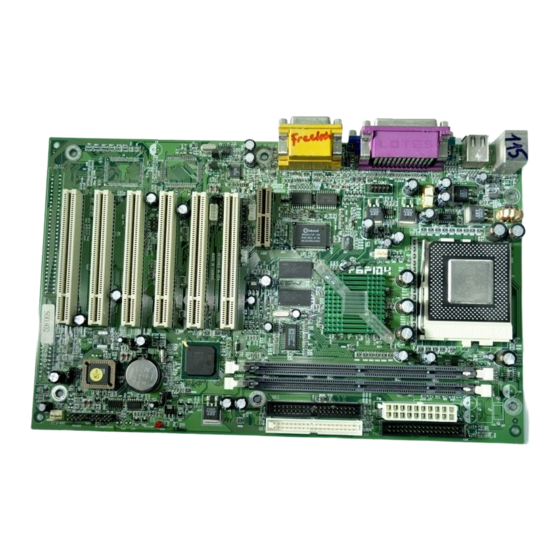
Page 10: P6F104 Mainboard Layout
Chapter 1: Introduction 1.3 P6F104 Mainboard Layout PCI6 PCI5 PCI4 SB-LINK PCI3 PCI2 M D 1 VCC33SBY LED C D 2 PCI1 1: CPU Socket 10: ISA Expansion Slots 18: ATX Power Connector 2: CPU FAN Connector 11: SB-LINK 19: Dual USB Connector... -
Page 11: Microprocessor
1.4 Microprocessor The P6F104 mainboard is designed to operate with the Intel® Celeron™ processor in PPGA (Plastic Pin Grid Array) package which runs at 300A ~ 700+ MHz (66MHz FSB) and future CPU (100MHz FSB). The Intel Celeron processor (PPGA), implements a Dynamic Execution Micro-architecture and executes MMX™... -
Page 12: Chipset
N82802AB (FWH): - Flash ROM DATA 1.7 Main Memory The P6F104 mainboard provides two 3.3volt 168-pin DIMM sockets to support 8MB to 512MB SDRAM (Synchronous DRAM). The DIMM sockets support 1M x 64 (8MB), 2M x 64 (16MB), 4M x 64 (32MB), 8M x 64 (64MB), 16Mx64(128MB) and 32Mx64(256MB) DIMM in single- or double-sided modules. -
Page 13: Built-In Accelerated Graphics (Agp) Chip
BIOS. 1.8 Built-in Accelerated Graphics (AGP) Chip The P6F104 mainboard built-in accelerated graphics chip is the integrated Graphics Memory Controller with 64/96-bit data interface. The 3D graphics with the texturing and visual enhancements are up to 1024x768x16bit at 85hz refresh. -
Page 14: Keyboard, Mouse And Usb Interface
1.10 Keyboard, Mouse and USB Interface PS/2 keyboard, PS/2 mouse, and USB connectors are located on the back panel of the P6F104 mainboard. The 5V line to the PS/2 Keyboard and PS/2 Mouse connectors are protected with a PolySwitch circuit that acts like a self-healing fuse which will re- establishing the connection after an over-current condition is removed. -
Page 15: Real-Time Clock, Cmos Ram And Battery
1.11 Real-time Clock, CMOS RAM and Battery The integrated real-time clock (RTC) provides a time of day clock, and an 85-year calendar with alarm features. P6F104 also has 242 bytes battery backed CMOS RAM which stores the system setup information and password. The RTC and CMOS RAM can be set via the BIOS SETUP program. -
Page 16: System Power On/Off Control
Off feature to work properly, Power Management/APM must be enabled in the system BIOS and Operating System. The P6F104 Auto Power On feature gives you the option to turn on the system power automatically when the AC power failure happen, is especially useful for the server application. -
Page 17: System Sleep / Resume
Magic Packet (MP Wake-up) it asserts a wake up signal that powers up the computer. Note: For Wake on LAN, the 5-V standby line for the power supply must be capable of delivering 5V with 5% tolerance at 720mA. P6F104 User’s Manual... -
Page 18: Hardware Installation
2.2 Installation Steps The P6F104 is designed to fit into a standard ATX form factor chassis. The pattern of the mounting holes and the position of the back panel connectors meet the ATX system board specification. -
Page 19: Installing Cpu
You will feel some resistance as the pressure starts to secure the CPU in the socket. 4. Install a heatsink with a cooling fan that is required to protect the CPU from being damaged due to overheat. P6F104 User’s Manual... -
Page 20: Installing System Memory
Chapter 2:Hardware Installation 2.2.2 Installing System Memory The P6F104 support 100MHz SDRAM up to 512MB. If more than maximum size memory are populated on the P6F104 mainboard, the portion of the memory which exceed the boundary will be invalidated. The P6F104 Mainboard has two 168-pin DIMM Sockets. -
Page 21: Attaching Connectors
Chapter 2: Hardware Installation 2.2.3 Attaching Connectors P6F104 Mainboard Connector/Jumper Location System FAN PC SPEAKER OUT SELECTION PCI6 FALSH ROM LOCK/UNLOCK PCI5 PCI4 Creative Lab SB-Link connector SB-LINK PCI3 Clearance CMOS RAM PCI2 Disabled/Enabled M D 2 Modem Voice Input... - Page 22 Pin Assignment Function HDD LED+ 12 13 14 15 18 19 20 21 22 HDD LED- STB LED+ STB LED- Power Good Ground Power On/Off Ground Speaker out Ground Ground PW LED+ N.C. PW LED- Keylock Ground P6F104 User’s Manual...
- Page 23 Turbo mode when a slower speed is required for a specific application. The Intel 810 Whittney chipset does not support the hardware deturbo function. An alternative method of using <CTRL><ALT><+/-> keys to change the speed may be used if necessary. P6F104 User’s Manual...
- Page 24 2. +12V 3. SPEED / RPM There are two fan connectors on the P6F104 mainboard for the cooling fans. The connectors support fans of 12V DC/ 500mAMP (6 WATT) or less. When the system goes into sleep state, fan should be...
- Page 25 There is only one way to plug the lead Power ON/OFF into the ATX power connector. Press the lead Ground Ground connector down until the clip snaps into place Ground Ground Ground and secures the lead onto the connector. Power Good +5VSB +12V P6F104 User’s Manual...
- Page 26 This 1x4 header is used for CD-ROM Audio input signal. The pin out and connect type are different between CD1 and CD2. CD2 is MPC2 type connector which is for SONY/ATAPI CD-ROM. CD1 is JST type connector which is for MITSUMI/PANASONIC CD-ROM. P6F104 User’s Manual...
-
Page 27: Set Jumpers On The Mainboard
CMOS and password. JP23 1. Power off the system 2. Place a shunt to short pin2 and pin3 of JP23 for 5 seconds 3. Put the shunt back to pin1 and pin2 of JP23 4. Power on the system P6F104 User’s Manual... - Page 28 5. PC Sound Selection (JP33) This jumper allows user to select PC BIOS sound come from either PC speaker at JP33 JP26 front panel or Stereo SPK_OUT at Audio connector. JP33 JP33 PC Speaker Back panel’s audio port P6F104 User’s Manual...
-
Page 29: Set Cpu Speed In The Cmos Setup
CPU Voltage: There is no hardware or BIOS settings needed for CPU operating voltage. The switching regulator circuit can auto- detect the CPU type on the P6F104 mainboard and generate the proper operating voltage for the CPU. P6F104 User’s Manual... - Page 30 Refer to the table below and select the correct CPU speed. CMOS Setup Utility - Copyright (C) 1994-1999 Award Software Frequency/Ratio Control Item Help w Auto Detect DIMM/PCI Clk Enabled w CPU Clock/Spread Specturm Menu Level Default w CPU Ratio P6F104 User’s Manual...
- Page 31 Set jumper to clear CMOS RAM 1. Power off the system 2. Place a shunt to short pin2 and pin3 of JP23 for 5 seconds 3. Put the shunt back to pin1 and pin2 of JP23 4. Power on the system P6F104 User’s Manual...
-
Page 32: Bios Configuration
Chapter 3: BIOS Configuration BIOS Configuration After hardware configuration of P6F104 Mainboard is completed, and system hardware has been assembled, the completed system may be powered up. At this point, CMOS setup should be run to ensure that system information is correct. -
Page 33: Cmos Setup Utility
Listed below are explanations of the keys displayed at the bottom of the screen: <ESC>: Exit the utility. ARROW KEYS: Use arrow keys to move cursor to the desired selection. <F10>: Saves all changes made to Setup and exits program. P6F104 User’s Manual... -
Page 34: Standard Cmos Features
“Slave”. Hard disk Types from 1 to 45 are standard ones; Press <Enter> key for IDE Auto detection otherwise, Type “Press Enter or None” is IDE HDD auto detection; Type “User” is user definable, and Type “None” is not installed. P6F104 User’s Manual... - Page 35 Base Memory/Extended Memory/Total Memory Those informations are the system memory information. For MS- DOS format from 0~640K will assign to Base memory, the rest of memory will assign to Extended memory. P6F104 User’s Manual...
-
Page 36: Advanced Bios Features
CPU Internal Cache: The default setting is “Enabled”. This Setting enables the CPU internal cache. External Cache: The default setting is “Enabled”. This setting enables the Level 2 cache. P6F104 User’s Manual... - Page 37 “Enabled”, you can set the typematic Rate and typematic Delay. Typematic Rate (Chars/Sec): This setting controls the speed at which the system registers repeated keystrokes. The choices range from 6 to 30 Chars/Sec. The default setting is “6” Chars/Sec. P6F104 User’s Manual...
- Page 38 Report No FDD For Win95: The default setting is “Yes”. Set this option to “Yes” to request BIOS to report the FDD status to Windows 95. After you have made your selection(s) in the BIOS FEATURES SETUP, press the <ESC> key to go back to the main program screen. P6F104 User’s Manual...
-
Page 39: Advanced Chipset Featuress
SCAS#. The default setting is “Fast”. SDRAM RAS Precharge Time: The options are “Fast” and “Slow”. This option sets the length of time in terms of number of clocks required for the SDRAM RAS# precharge. The default setting is “Fast”. P6F104 User’s Manual... - Page 40 *Onboard Display Cache Setting/Paging Mode Control: The default setting is “Close”. The options are “Open” and “Close”. *Onboard Display Cache Setting/RAS-to-CAS Override: The options are “by CAS# LT” and “Override”. P6F104 User’s Manual...
-
Page 41: Integrated Peripherals
RxD, TxD Active Hi, Hi x IR Transmittiion Delay Enabled Onboard Parallel Port 378/IRQ7 Parallel Port Mode x EPP Mode Select EPP1.7 x ECP Mode Use DMA PWRON After PWR-Fail Game Port Address Midi Port Address Midi Port IRQ P6F104 User’s Manual... - Page 42 “Enabled” the onboard Audio codec or Audio codec on the AMR slot will function. When set to “Disabled” it will disabled onboard audio codec and AMR slot , this allows system use PCI audio. The default is “Enabled”. P6F104 User’s Manual...
- Page 43 Onboard Serial Port 1 and Onboard Serial Port 2: These options are used to assign the I/O addresses for two onboard serial ports. They can be assigned as follows: 3F8/ IRQ4, 2F8/ IRQ3 3E8/ IRQ4, 2E8/ IRQ3 Auto (default) Disabled (Disable the onboard serial port) P6F104 User’s Manual...
- Page 44 Game port I/O Address. MIDI Port Address: The options are “330”, “300” or “Disabled”. This will set onboard MIDI port I/O Address. MIDI Port IRQ: The options are “5” or “7”. This will set onboard MIDI port IRQ. P6F104 User’s Manual...
-
Page 45: Power Management Setup
STR function will be enabled; if not, this function will be disabled. If the expansion cards you use on the mainboard do not support the STR function, you must leave this field on the default setting “S1(POS)”. P6F104 User’s Manual... - Page 46 [8Min] [12Min] [20Min] [30Min] [40Min]... [1Hour]. The default setting is “Disabled”. HDD Power Down: Options are from “1 Min” to “15 Min” and “Dis- abled”. The IDE hard drive will spin down if it is not accessed within a specified length of time. P6F104 User’s Manual...
-
Page 47: Pnp / Pci Configuration
& DMAs. You must set up the IRQ and DMA assignments cor- rectly thru the PnP/PCI Configuration Setup utility, otherwise the Mainboard will not work properly. Selecting “PNP / PCI CONFIGURATION” on the main program screen the following menu will display: P6F104 User’s Manual... - Page 48 CPU is only directed to the PCI VGA card's palette registers. If set to “Enabled”, data read and written by CPU will be directed to both the palette registers of the PCI VGA and ISA VGA P6F104 User’s Manual...
-
Page 49: Pc Health Monitor
Current CPU Temperature: The onboard hardware monitor is able to detect the CPU temperatures. Current CPU FAN and SYSTEM FAN Speed: The onboard hardware monitor is able to detect the CPU fan speed and the system fan speed. The presence of the fans is automatically detected. P6F104 User’s Manual... -
Page 50: Frequency/Ratio Control
CPU Ratio: This option sets the CPU Core to Bus Clock Multiplier. The options are “3”, “3.5”, ”4”, “4.5”, “5”, “5.5”, “6”, “6.5”, “7”, “7.5”, “8”. P6F104 User’s Manual... -
Page 51: Load Optimized Default
CMOS memory by turning power off and placing a shunt on the JP23 to short pin 2 and pin 3 for 5 seconds, then putting the shunt back to pin1 and pin2 of JP23. P6F104 User’s Manual... -
Page 52: Save & Exit Setup
CMOS memory and continue with the booting process. 3.14 Exit Without Saving Selecting this option and pressing the <Enter> key will exit the Setup Utility without recording any new values or changing old ones. P6F104 User’s Manual... -
Page 53: Driver And Utility
4 Driver and Utility 4.1 Flash Utility The BIOS of the P6F104 mainboard can be upgraded by using a Flash utility. A new version of the BIOS can be downloaded from the factory's BBS and Web site. The system BIOS is stored in a 4M-bit Flash EEPROM which can be erased and reprogrammed by the Flash utility. - Page 54 Chapter 4: Driver and Utility Click “Next” to Continue the Installation. Click “Yes” to Accept the Agreement. Click “Next” to Agree Installing the Read Me. P6F104 User’s Manual...
- Page 55 Read Me to the Default Folder. Otherwise, Click “Browse” to Choose Desire Folder Location. Click “Next” to Install the INF Files to Properly Configure the Intel Chipsets. Click “Yes” to Restart the Computer and Finish the Installation. P6F104 User’s Manual...
-
Page 56: Intel 810 Chipset Graphic Driver Software
Step 2. Click the “Install Driver” option in your installation screen. Step 3. Click the “Intel\AGP” option to start the installation. Step 4. Follow the instruction to finish the installation: Click “Next” to Continue the Installation. Click “Yes” to Accept the Agreement. P6F104 User’s Manual... - Page 57 Chapter 4: Driver and Utility Click “Next” to Install the Chipset Graphic Driver to the Default Folder. Click “Browse” to Choose Desire Folder Location. Click “Yes” to Restart the Computer and Finish the Installation. P6F104 User’s Manual...
-
Page 58: On Board Codec Drive
On Board Codec Driver. Step 3. Follow the instruction finished the installation: Under the “Device Manager”, Click “OK” to Start the Installation Setup Process. Under the “General” Properties, Click “OK” to Continue the Installation Setup Process. P6F104 User’s Manual... - Page 59 Process. Click “Next” to Continue the Installation Setup Process After Choose the One of the 2 Options that is Shown on the Screen. Select the Type of Device, then Clcik “Next” to Continue the Installation Setup Process. P6F104 User’s Manual...
- Page 60 Model, then Click “Next” to Continue the Installation Setup Process. Choose the Correct Drive and Clcik “OK” to Continue the Installation Setup Process. Click “OK” to Continue the Installation Setup Process. Click “Next” to Start the Installation. P6F104 User’s Manual...
- Page 61 Chapter 4: Driver and Utility Click “Finish” to End the Installation. Click “Close” to Finish installing Crystal WOM Audio Codec Driver. Click “OK” to Finish Check the Driver Install OK. P6F104 User’s Manual...
-
Page 62: Intel Security Controller Driver
Step 2. Click the “Install Driver” option in your installation screen. Step 3. Click the “Intel\Security” option to start the installation. Step 4. Follow the instruction to finish the installation: Click “Next” to Continue the Installation. Click “Next” to Agree the Notes. P6F104 User’s Manual... - Page 63 Security Driver to the Default Folder. Otherwise, “Browse” to Choose Desire Folder Location. Click “View Readme” to View the Readme Document. Or, Click “Restart” to Restart and Complete the Installation. Or, Click “Restart Later” to to Complete the Installation Later. P6F104 User’s Manual...
-
Page 64: System Environment Monitor Utility (Optional)
Otherwise, Click “Exit Setup” to Close Files to Restart the Installation Process Again. Click the button to start the installation. Click “Change Directory” to Change the Install Direction which Other than the Defult -- C:\Program Files\ HWDoctor\. P6F104 User’s Manual... - Page 65 Chapter 4: Driver and Utility Click “OK” to Complete the Installation. Then, the Following Screen will Show Up in Your Screen. P6F104 User’s Manual...
-
Page 66: Creative Lab Sb Audiopci 64V (Optional)
\CTRUN directory and executes the CTRUN.EXE command, which will force the installation screen to pop-out. 2)Click on “install” and follows the instruction on the screen to create the directory and finished the installation. P6F104 User’s Manual... - Page 67 For the MIDI audio edit tools Creative Remote This function is not support yet. Creative Wave For the WAV audio edit tools SB Audio 64V Mixer For Audio Mixer Sound ‘s LE For Line-in or Microphone record P6F104 User’s Manual...
-
Page 68: Debug & Troubleshooting
5 Debug & Troubleshooting 5.1 Debug LED (Optional) The P6F104 mainboard comes with a unique debug LED design to help system integrator to catch up the problem right away. There are three debug LED close to the front panel connector LED1 LED2, LED3. - Page 69 Online Services Online Services Freetech is a leading designer and manufacturer of high performance system boards for desktop PCs, workstations and network servers. Since its inception in the heart of Silicon Valley in 1990, it has continued to provide valued products to its customers by focusing on service, quality and technology.
Need help?
Do you have a question about the P6F104 and is the answer not in the manual?
Questions and answers