Table of Contents
Advertisement
Quick Links
Advertisement
Table of Contents

Related Manuals for Freetech P6F127


Summary of Contents for Freetech P6F127
- Page 1 P6F127 Mainboard Manual Friday, March 02, 2001...
- Page 3 Copyright Notice ©Copyright 2000 The information contained in this user’s manual and all accompany- ing documentation is copyrighted and all rights are reserved. This publication may not, in whole or in part, be reproduced, transcribed, stored in a retrieval system, translated into any language or com- puter language, or transmitted in any form whatsoever without the prior written consent from the manufacturer, except for copies re- tained by the purchasers for their personal archival purposes.
- Page 4 Preface Using This Manual This manual is designed to help you build a reliable Personal Com- puter based on the P6F127 platform. Chapter 1—Quick Reference This chapter is for advanced users who want to quickly assemble a system. The mainboard layout along with jumper and switch settings, and memory configuration are provided.
-
Page 5: Table Of Contents
Preface Table of Contents 1. P6F127 QUICK REFERENCE 1.1. Mainboard Layout ............1 1.2. I/O Ports (AC97) ............2 1.3. I/O Ports (Ensoniq CT5880)........... 2 1.4. Panel Connector ............2 1.5. Jumpers ................. 3 1.6. PCI and AGP Frequency Settings ........3 1.7. - Page 6 Preface 3.6.3. Removing the Processor..............25 3.6.4. Installing System Memory...............26 3.6.5. Setting Jumpers ................28 3.6.6. Auto Power On .................29 4. BIOS CONFIGURATION 4.1. Entering Setup............. 31 4.2. Standard CMOS Setup ..........33 4.3. BIOS Features Setup........... 37 4.4. Chipset Features Setup ..........40 4.5.
-
Page 7: P6F127 Quick Reference
1. P6F127 Quick Reference This section is for users to get started using the mainboard straight away. 1.1. Mainboard Layout PS/2 POWER1 mouse/keyboard ports ports Parallel serial ports Game audio ports IDE1 IDE2 JP20 PCI1 USB2 PCI2 LAN WAKE UP... -
Page 8: I/O Ports (Ac97)
Mainboard User’s Manual 1.2. I/O Ports (AC97) Parallel port (LPT1) PS/2 Game port Line-out mouse Line-in ports PS/2 Microphone keyboard Serial port Serial port COM 1 COM 2 1.3. I/O Ports (Ensoniq CT5880) Parallel port (LPT1) PS/2 Game port Line-out (front) mouse Line-in (rear) ports... -
Page 9: Jumpers
P6F127 Quick Reference 1.5. Jumpers 1-2, 3-4, 5-6, 7-8: CPU ratio = 2X 1-2, 3-4, 7-8: CPU ratio = 2.5X 1-2, 5-6, 7-8: CPU ratio = 3X 1-2, 7-8: CPU ratio = 3.5X 3-4, 5-6, 7-8: CPU ratio = 4X 3-4, 7-8: CPU ratio = 4.5X... -
Page 10: Connectors
Mainboard User’s Manual 1.7. Connectors FAN1 CPU FAN Connector: This 3-pin header is used for con- necting the CPU fan. CD1/2 CD Connectors: These 4-pin headers are used for con- necting the CD ROM audio input to the sound card. USB2 USB Connector: This 8-pin. -
Page 11: Introduction
2. Introduction 2.1. Overview The P6F127 is a high quality, high performance, enhanced function mainboard that supports 64-bit Intel Celeron/Cyrix Socket 370 proc- essors. This mainboard is designed around the latest and fastest Apollo Pro133A chipset in a standard ATX form factor. -
Page 12: Mainboard Specifications And Features
Mainboard User’s Manual 2.2. Mainboard Specifications and Features 2.2.1. Hardware Celeron/Cyrix Socket 370 processors Onboard Voltage Regulator Module Provides 1.3V to 3.5V operating voltage Coprocessor CPU has built-in floating point unit Speed System bus clock 66/100/133 MHz AGP 1x/2x/4x PCI bus clock 33 MHz ISA bus clock 8.33~9.35 MHz Chipset Apollo Pro133A:... -
Page 13: Software
Introduction Power Compliant with EPA, APM 1.2 and ACPI Management ATX soft-off power control Power – on by keyboard and PS/2 mouse Power – on by external modem ring Power – on by alarm Power – on by LAN wake up Fan off in sleep mode System CPU temperature warning and system temperature... -
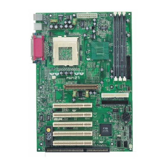
Page 14: Mainboard Layout
Mainboard User’s Manual 2.3. Mainboard Layout Note: Because of optional items and design changes, your mainboard may not be identical to the one shown in the illus- tration. Mainboard Layout... - Page 15 Introduction Key to Mainboard Components Name Function PGA370 CPU socket POWER1 ATX power connector DIMM1~3 Memory module slots Floppy drive connector CPU FAN CPU cooling fan connector (FAN1) Accelerated Graphics Port (AGP) slot IDE1 IDE1 connector (white) IDE2 IDE2 connector (black) USB2 Front panel USB connector RTC battery...
-
Page 16: Microprocessor
Mainboard User’s Manual 2.4. Microprocessor The mainboard is designed to operate with the following processors: Processor Type Speed Intel Celeron 466 ~ 766+ MHz 66 MHz Intel Coppermi n e 500 ~ 850+ MHz 100 MHz Intel Coppermi n e 533 ~ 933+ MHz 133 MHz VIA Cyrix III... -
Page 17: Chipset
Introduction 2.7. Chipset The P6F127 supports the VIA 82C694X Apollo Pro-133A chipset. The chipset comes in pairs—the North Bridge chip and the South Bridge chip. • CPU interface controller (66/100/133 MHz FSB) North Bridge • AGP interface controller (AGP 1x/2x/4x) •... -
Page 18: Hardware Installation
Of course, you can use the system I/O ports and expansion slots to add many more features and components to your system than the items listed above. 3.1. Unpacking The P6F127 mainboard package contains the following items: q One mainboard q One IDE 40-pin ribbon cable q One floppy 34-pin ribbon cable... -
Page 19: Installation
Hardware Installation 3.2. Installation The P6F127 is designed to fit into a standard ATX form factor chas- sis. The pattern of the mounting holes and the position of the back panel connectors meet the ATX system board specification. The chassis comes with various mounting fasteners, which are made of metal or plastic. -
Page 20: Connector/Jumper Location
Mainboard User’s Manual 3.4. Connector/Jumper Location POWER1 IDE1 IDE2 JP20 PCI1 USB2 PCI2 LAN WAKE UP MODEM WAKE UP JP19 PCI3 PCI4 PCI5 Connector/Jumper Location... -
Page 21: Attaching Connectors
Hardware Installation 3.5. Attaching Connectors 3.5.1. Front Panel Connectors There are six connectors on the mainboard for speaker, switches, and indicator lights on the system’s front panel. P O W E R 1 Front Panel Connectors Ground Ground POWER SWITCH Power on/off Keylock POWER LED... -
Page 22: Infrared (Ir) Connectors
Mainboard User’s Manual 3.5.2. Infrared (IR) Connectors This 5-pin connector connects to an optional wireless transmitting and receiving infrared module via a cable and a bracket. Configure BIOS to enable the IrDA port if you attach an infrared module to this connector. -
Page 23: Lan/Modem Wake Up Connectors
Hardware Installation 3.5.4. LAN/Modem Wake Up Connectors These 3-pin headers are used for remote wake up of the computer through a network or modem signal. POWER1 Modem Wake Up Connector WOM1 Pin 1 LAN Wake Up Connector WOL1 IDE1 IDE2 JP20 Pin 1 PCI1... -
Page 24: Ide Connectors
Mainboard User’s Manual 3.5.6. IDE Connectors An IDE drive ribbon cable has two connectors to support two IDE drives. If a ribbon cable connects to two IDE drives at the same time, one of them has to be configured as Master and the other has to be configured as Slave by setting the drive select jumpers on the drive. -
Page 25: Back Panel Connectors
Hardware Installation 3.5.8. Back Panel Connectors The back panel provides external access to PS/2 style keyboard and mouse connectors, two serial ports, one parallel port, dual USB ports, a game port and audio ports which are integrated on the mainboard. The figures below show the location of the back panel I/O connec- tors. - Page 26 Mainboard User’s Manual Parallel Port Connect a printer or other parallel device to the burgundy-colored 25-pin parallel port. You can set the parallel port IRQ and parallel port mode in BIOS. Refer to Integrated Peripherals in Chapter 4 for details. Parallel Port Serial Ports Connect a serial device such as a mouse or modem to the turquoise 9-...
- Page 27 Hardware Installation Audio Port Connectors (AC97) You can connect various audio devices to these audio jacks. Connect headphones or powered speakers to the lime-colored lineout connec- tor. Connect a tape player or another audio source to the light blue Line-in connector to record audio on your computer or to play audio through your computer’s sound chip and speakers.
- Page 28 Mainboard User’s Manual Power Supply Connector The ATX power supply has a single lead connector with a clip on one side of the plastic housing. There is only one way to plug the lead into the ATX power connector. Press the lead connector down until the clip snaps into place and secures the lead onto the connector.
- Page 29 Hardware Installation CPU/System Fan Power Supplies There are two fan connectors on the mainboard for the cooling fans. The connectors support fans of 12V DC/500mAMP (six watt) or less. When the system goes into sleep state, fans should be shut down to eliminate audible noise and reduce power consumption.
-
Page 30: Installing The Cpu
Mainboard User’s Manual 3.6. Installing the CPU 3.6.1. Before You Begin Be sure that your processor kit includes the following items: ♦ One processor with the fan or heat sink attached ♦ One power cable (for CPU with cooling fan attached) Place the mainboard on a workbench (not in a chassis). -
Page 31: Removing The Processor
Hardware Installation Identify the pin-1 corner of the PGA370. The pin-1 corner is on the same side as the locking lever, as shown in the il- lustration below. Identify the pin-1 corner of the processor (the pin-1 corner on the processor has a beveled edge). Socket Lever Processor Pin-1... -
Page 32: Installing System Memory
Mainboard User’s Manual 3.6.4. Installing System Memory Maximum system memory supported by the mainboard is 1.5 GB. The mainboard has three DIMM Sockets. Memory can be installed using 168-pin SDRAM DIMM memory modules. There are no jumper settings required for the memory size or type, which is auto- matically detected by the BIOS. - Page 33 Hardware Installation Due to the high-speed design of the mainboard, the memory modules must meet the following requirements: DRAM TYPE SDRAM (Synchronous DRAM) Module Size Single Sided Asymmetric 1Mx64, 4Mx64, 8Mx64, 16Mx64 Double-Sided Asymmetric 2Mx64, 4Mx64, 8Mx64, 16Mx64, 32Mx64 Requirements SDRAM Extended Data Output Synchronous DRAM...
-
Page 34: Setting Jumpers
Mainboard User’s Manual 3.6.5. Setting Jumpers Refer to the following illustration and instructions to set the jumpers on your mainboard. FSB Speed Settings POWER1 Pin 1 OnChip Sound Settings JP20 Pin 1 CPU Clock Ratio Settings Pin 1 Suspend To RAM Settings IDE1 JP19 IDE2... -
Page 35: Auto Power On
Hardware Installation Clear CMOS/Password Jumper You may need to clear the CMOS if your system cannot boot up be- cause you forgot your password, the CPU clock setup is incorrect, or the CMOS settings need to be reset to default values after the system BIOS has been updated. -
Page 36: Bios Configuration
4. BIOS Configuration After the hardware configuration of the mainboard is finished, and the system hardware has been assembled, the system may be pow- ered up. At this point, CMOS setup should be run to ensure that system information is correct. The mainboard employs the latest Award BIOS CMOS chip with support for Windows Plug and Play. -
Page 37: Entering Setup
BIOS Configuration This program should be executed under the following conditions: • When changing the system configuration • When a configuration error is detected by the system and you are prompted to make changes to the Setup program • When resetting the system clock •... - Page 38 Mainboard User’s Manual After the POST routines are completed, the following message ap- pears: “Press DEL to enter SETUP” To access the AWARD BIOS SETUP program, press the <DEL> key to display the “CMOS SETUP UTILITY” screen: CMOS Setup Utility – Copyright (C) 1984 – 2000 Award Software Standard CMOS Features Frequency/Voltage Control Load Optimized Defaults...
-
Page 39: Standard Cmos Setup
BIOS Configuration 4.2. Standard CMOS Setup Standard CMOS Setup is the same for all three chipsets. Selecting “STANDARD CMOS SETUP “on the main program screen displays the following menu: CMOS Setup Utility – Copyright (C) 1984 – 2000 Award Software Standard CMOS Features Date (mm:dd:yy) Tue, July 8 2000... - Page 40 Mainboard User’s Manual CMOS Setup Utility – Copyright © 1984 – 2000 Award Software IDE Primary Master IDE HDD Auto-Detection Press Enter Item Help IDE Primary Master Auto Menu Level Access Mode Auto To auto-detect the Capacity 0 MB HDD’s size, head . . . on Cylinder this channel Head...
- Page 41 BIOS Configuration IDE Primary/Secondary Master/Slave: If you leave this item at “Auto,” the system will automatically detect and configure any IDE devices it finds. If it fails to find a hard disk, change the value to “Manual” and then manually configure the drive by entering the characteristics of the drive in the items below (Capacity, Cylinder, Head, Precomp, etc.).
- Page 42 Mainboard User’s Manual Halt On: This setting determines which type of errors will cause the system to halt during bootup. The options are: • All Errors • No Errors • All, But Keyboard (default) • All, But Diskette • All, But Disk/Key Base/Extended/Total Memory: These items are automatically de- tected by the system at start up time.
-
Page 43: Bios Features Setup
BIOS Configuration 4.3. BIOS Features Setup Selecting “BIOS Features Setup” on the main program screen dis- plays this menu, which allows you to define advanced information about your system. You can make modifications to most of these items without introducing fatal errors to your system. Note that the page has a scroll-bar to scroll down to more items. - Page 44 Mainboard User’s Manual External Cache: This setting enables the Level 2 cache. The default setting is “Enabled.” CPU L2 Cache ECC Checking: This item enables or disables ECC (Error Correction Code) error checking on the CPU cache memory. The default setting is “Disabled.” Processor Number Feature: Some new processors are installed with a unique processor number.
- Page 45 BIOS Configuration Gate A20 Option: This option accesses memory above 1 MB using the fast gate A20 line when set to “Fast” (default). The other option is “Normal.” Typematic Rate Setting: If set to “Enabled,” enables you to set the Typematic Rate and Typematic Delay.
-
Page 46: Chipset Features Setup
Mainboard User’s Manual 4.4. Chipset Features Setup Selecting “Chipset Features Setup” on the main program screen dis- plays this menu: CMOS Setup Utility – Copyright (C) 1984 – 2000 Award Software Advanced Chipset Features Bank 0/1 DRAM Timing SDRAM 8/10ns Item Help Bank 2/3 DRAM Timing SDRAM 8/10ns... - Page 47 BIOS Configuration DRAM Clock: Enables the user to select the DRAM Clock. SDRAM Cycle Length: This field enables you to set the CAS l a - tency time in HCLKs of 2/2 or 3/3. The system board designer should have set the values in this field, depending on the DRAM in- stalled.
- Page 48 Mainboard User’s Manual AGP Fast W rite: This item allows you to enable or disable the cach- ing of display data for the video memory of the processor. Enabling can greatly improve the display speed. If your graphics display card does not support this feature, you need to disable this item.
- Page 49 BIOS Configuration AGP Master 1 WS Read: This implements a single delay when reading to the AGP Bus. By default, two-wait states are used by the system, allowing for greater stability. The default is “Disabled.” Memory Parity/ECC Check: Enable this item to allow BIOS to perform a parity/ECC check to the POST memory tests.
-
Page 50: Integrated Peripherals
Mainboard User’s Manual 4.5. Integrated Peripherals Selecting “Integrated Peripherals” on the main program screen dis- plays this menu: CMOS Setup Utility – Copyright (C) 1984 – 2000 Award Software Integrated Peripherals On-Chip IDE Channel0 Enabled Item Help On-Chip IDE Channel1 Enabled IDE Prefetch Mode Enabled... - Page 51 BIOS Configuration manually to a lower mode, e.g., from Mode 3 to Mode 2. All IDE drives should work with PIO mode 0. There are six options: • Auto (default) • Mode 0 • Mode 1 • Mode 2 • Mode 3 •...
- Page 52 Mainboard User’s Manual IR Function Duplex: This field is available when UART 2 Mode is set to either ASKIR or HPSIR. This item enables you to determine the infrared (IR) function of the onboard infrared chip. Full-duplex means that you can transmit and send information simultaneously. Half duplex (default) is the transmission of data in both directions, but only one direction at a time.
- Page 53 BIOS Configuration SB I/O Base Address: This item lets you set the I/O base address for the Sound Blaster card. There are four options: • 220H (default) • 240H • 260H • 280H SB IRQ Select: This item lets you set the Interrupt Request (IRQ) for the Sound Blaster card.
-
Page 54: Power Management
Mainboard User’s Manual 4.6. Power Management Power Management Setup controls the mainboard’s “Green” fea- tures. Selecting “Power Management Setup” on the main program screen displays this menu: CMOS Setup Utility – Copyright (C) 1984 – 2000 Award Software Power Management Setup ACPI Function Enabled Item Help... - Page 55 BIOS Configuration Power Management: This item enables you to choose the type of Power Management you want. Selecting Power Management and pressing <Enter> displays the following screen: CMOS Setup Utility – Copyright (C) 1984 – 2000 Award Software Power Management Power Management User Define Item Help...
- Page 56 Mainboard User’s Manual ACPI Suspend Type: Use this item to define how your system sus- pends. In the default, S1(POS), the suspend mode is equivalent to a software power down. If you select S3 (STR), the suspend mode is a suspend to RAM –...
- Page 57 BIOS Configuration State After Power Failure: This sets the power state after a power failure. If the value is set to “ON,” the system turns back on. If the value is set to “OFF,” the system remains turned off. If the value is set to “Auto,”...
- Page 58 Mainboard User’s Manual Resume by Ring: When set to “Enabled,” any activity on the Mo- dem port will wake up the system from a power saving mode. The options are “Enabled” and “Disabled” (default). Resume by Alarm: When set to “Enabled,” you may set the date (day of the month), hour, minute and second to turn on your system.
-
Page 59: Pnp/Pci Configuration
BIOS Configuration 4.7. PnP/PCI Configuration Both the ISA and PCI buses on the Mainboard use system IRQs (In- terrupt ReQuests) and DMAs (Direct Memory Access). You must set up the IRQ and DMA assignments correctly through the PnP/PCI Configuration Setup utility; otherwise, the mainboard will not work properly. - Page 60 Mainboard User’s Manual Resources Controlled By: The default setting is “Manual” which al- lows you to control IRQs and DMAs individually. The other option is “Auto” which will detect the system resources and automatically assign the relative IRQs and DMAs for each peripheral. IRQ and DMA Resources: These fields only become available if the Resources Controlled By field is set to “Manual.”...
-
Page 61: Pc Health Status Option
BIOS Configuration 4.8. PC Health Status Option On mainboards that support hardware monitoring, this item lets you monitor the parameters for critical voltages, critical temperatures, and fan speeds. Selecting “PC Health Status” on the main program screen displays this menu: CMOS Setup Utility –... -
Page 62: Frequency/Voltage Control
Mainboard User’s Manual These fields provide you with information about the systems current operating status. You cannot make changes to these fields. The fol- lowing information is displayed: • CPU temperature • System temperature • CPU FAN speed (in RPMs) •... -
Page 63: Load Optimized Defaults Option
BIOS Configuration Auto Detect DIMM/PCI C1K: When this item is enabled, BIOS will disable the clock signal of free DIMM and PCI slots. Spread Spectrum: If you enable spread spectrum, it can signifi- cantly reduce the EMI (Electro-Magnetic Interference) generated by the system. -
Page 64: Supervisor/User Password
Mainboard User’s Manual 4.11. Supervisor/User Password The “Supervisor/User Password” utility sets the password. The mainboard is shipped with the password disabled. If you want to change the password, you must first enter the current password, then at the prompt enter your new password. The password is case sensi- tive. -
Page 65: Driver And Utility
5. Driver and Utility 5.1. Flash Utility The BIOS of the P6F127 mainboard can be upgraded by using a Flash utility. A new version of the BIOS can be downloaded from the factory's BBS and Web site. The system BIOS is stored in a 1 M-bit Flash EEPROM that can be erased and reprogrammed by the Flash utility. -
Page 66: System Environment Monitor
Mainboard User’s Manual 5.3. System Environment Monitor The System Environment Monitoring utility along with the onboard VT82C686A system monitor chip enables you to monitor your sys- tem’s operating characteristics such as temperature, fan speed and CPU voltage. Using this utility, you can define the upper and lower limits of these monitored parameters. -
Page 67: Setting The Threshold
Driver and Utility Click on the “VIA Hardware Monitor System” icon to ac- cess the program. 5.3.2. Setting the Threshold Set the threshold for system temperature, voltages and fan speeds. System Environment Monitor... -
Page 68: Ata66/100 Controller Options
Mainboard User’s Manual 5.4. ATA66/100 Controller Options When using the ATA66/100 controller, the BIOS setting will allow users to “Set Device Mode” and “Select Boot Sequence.” Setting Device Mode: Choose UDMA ( 0 ~4), PIO (0~4), and MW DMA (0~2) setting options transfer mode for any hard disks (ATA66/100) controlled by VT82C686A/VT82C686B. - Page 69 Driver and Utility Click on the option that you want to install. Follow the on-screen instructions to complete the installa- tion process. DOS Installation The DOS drivers are automatically installed during the Windows in- stallation process. Ensoniq Installation (optional)
-
Page 70: Online Services
Mainboard User’s Manual 5.6. Online Services Flexus Computer Technology, under the Freetech brand name, has consistently won recognition for excellence in the design and manu- facturing of high quality mainboards! Our products are globally recognized among the leading cost- performance mainboards in the industry today and we are a certified...
Need help?
Do you have a question about the P6F127 and is the answer not in the manual?
Questions and answers