Table of Contents
Advertisement
Quick Links
Advertisement
Table of Contents

Related Manuals for Freetech P6F135


Summary of Contents for Freetech P6F135
- Page 1 2$. !# MOTHER BOARD USER’S MANUAL...
- Page 2 Copyright Notice © Copyright 2001 The information contained in this user’ s manualand all accompa- nying documentation is copyrighted and all rights are reserved. This publication may not, in whole or in part, be reproduced, transcribed, stored in a retrieval system, translated into any language or com-puter language, or transmitted in any form whatsoever without the prior written consent from the manufac- turer, except for copies retained by the purchasers for their...
- Page 3 Using This Manual This manual is designed to help you build a reliable Personal Computer based on the P6F135 platform. Chapter 1 - Quick Reference This chapter is for advanced users who want to quickly assemble a system. The mainboard layout along with jumper and switch settings, and memory configuration are provided.
-
Page 4: Table Of Contents
Table of Contents 1. P6F135 QUICK REFERENCE ..........1 1.1. Mainboard Layout ............1 1.2. I/O Ports ................2 1.3. Front Panel Connector ............. 2 1.4. Jumpers ................3 1.5. PCI and AGP Frequency Settings ........3 1.6. Memory Installation ............3 1.7. Connectors ...............4 2. - Page 5 Preface 3.5.3. Audio CD-In Connector (JP9) ..........18 3.5.4. Audio Line-Out Connector (JP4) ........... 19 3.5.5. LAN LED Connector (J37) ............ 19 3.5.6. Audio Mic-In and Line-In Connectors (JP1) ......20 3.5.7. ICH2 GPIO Pin Connectors (J35/J36) ........20 3.5.8. Case Open Connector (J25) ........... 21 3.5.9.
- Page 6 Preface 4.5. Integrated Peripherals ............ 49 4.6. Power Management Setup ..........54 4.7. PnP/PCI Configurations ..........58 4.8. PC Health Status Option ..........59 4.9. Frequency/Voltage Control..........61 4.10. Load Optimized Defaults Option ........63 4.11. Set Supervisor/User Password ........63 4.12. Save & Exit Setup ............64 4.13.
-
Page 7: P6F135 Quick Reference
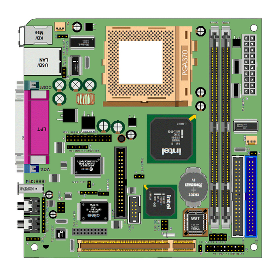
1. P6F135 Quick Reference This section is for users to get started using the mainboard straight away. 1.1. Mainboard Layout VGA PORT, SE RIAL P ORT & MIC-IN LINE-O UT 1394 PARALL EL POR PS /2 MOUS E & PO RT... -
Page 8: I/O Ports
Mainboard User’s Manual 1.2. I/O Ports Par allel p ort L A N po rt PS /2 M o us e po rt IEE E-13 9 C o nn ect or L in e-O ut M IC -In U SB p o rts PS /2 K ey bo ard po VG A p or t C O M 1 po rt... -
Page 9: Jumpers
P6F135 Quick Reference 1.4 Jumpers Normal Mode Clear Password (PSW) Normal Mode Clear CMOS O pen NC Short Controller Assign Vcc 5V O pen Book block protect Short Reflashing the BIOS Enabled Mouse & Keyboard Power-O JP11 Disabled Mouse & Keyboard Power-On 1.5. -
Page 10: Connectors
Mainboard User’s Manual 1.7. Connectors CPU/Chipset FAN C o nnector: This 3-pin header is use FA N2 for connecting a CPU chipset fan. System Fan Connector: This 3-pin header is for FA N3 connecting the case fan that keeps the system cool. 1394 Connector: This 6-pin header is used for connecting a 1394 devices. - Page 11 P6F135 Quick Reference LA N LED Connector: This 3-pin header is used for connecting LAN LED cable on the front panel. PS/2 Mouse and Keyboard Connectors: This 6-pin JP13 header is used for connecting cable at the front panel PS/2 Mouse and Keyboard of mainboard.
-
Page 12: Introduction
The high quality P6F135 is a high performance, enhanced function mainboard that supports 64-bit Intel FC-PGA, FC-PGA2, and Pentium III/ ® Cyrix Socket 370 processors. The P6F135 is based on the Intel 815EG B-Step chipset. Intel delivers superior high performance with all the ®... -
Page 13: Mainboard Specifications And Features
Introduction 2.2. Mainboard Specifications and Features 2.2.1. Hardware Intel® FC-PGA, FC-PGA2 Pentium® III/Cyrix Socket 370 Processors, Tualatin or other compatible Auto-detection CPU Onboard Voltage Regulator Module Provides 1.05V to 1.825V operating voltage CPU has built-in floating point unit Coprocessor Speed System bus clock 66/100/133 MHz PCI bus clock 33 MHz Chipset... -
Page 14: Software
Mainboard User’s Manual Expansion One 32-bit PCI slot Slots One Digital Video ouptup header One CNR header Compliant with EPA, APM 1.2 and ACPI Power Management Auto Power on ATX soft-off power control Power – on by keyboard and PS/2 mouse Power –... -
Page 15: Environment
Introduction Driver and IDE Bus mastering Ultra DMA driver Utility Flash utility for BIOS upgrade System Environment Monitoring Utility Optional AD1881A audio drivers Operating Operates with MS_DOS, Windows 3.x/9x/ME/XP/ System 2000/NT, OS/2, Novell NetWare/UnixWare 1.1, and SCO Unix 4.2 2.2.3. Environment Ambient Temperature 0ºC to 50ºC (operating) -
Page 16: Mainboard Layout
Mainboard User’s Manual 2.3. Mainboard Layout VG A PO RT, SERIAL PO R T & MIC -IN L IN E-O UT 13 9 PA RA LL EL PO R T PS/2 M O USE & PO RT PO RT PO RT L AN &... - Page 17 Introduction Key to Mainboard Components Name Function PGA 370 CPU socket ATX power connector DIMM1~ Memory module slots FLP1 Floppy drive connector IDE1 ID E 1 connector (blue) IDE2 ID E 2 connector (white) Digital Vidio output port PCI1 32-bit PCI slot 6-pin 1394 header JP16 CO M2 connector...
-
Page 18: Microprocessor
Mainboard User’s Manual Name Function ID E VCC JP11 PS/2 Mouse and Keyboard Power-O RTX battery Flash BIOS 2.4. Microprocessor The mainboard is designed to operate with the following processors: Processor Type Intel FC-PGA C eleron 66/100 MHz Intel FC-PGA Pentium III 100/133 MH z Intel FC-PGA2 (Tualatin) Pentium III 133 MHz... -
Page 19: Chipset
Introduction 2.6. Chipset The P6F135 supports the Intel 815EG chipset. The 815EG chipset is designed for desktops and workstations that provide internal or external graphics, and provides ATA-100 and SDRAM support. The 82801BA I/O controller hub makes a direct connection between the graphics system, the IDE controller, and the PCI bus. -
Page 20: Hardware Installation
Of course, you can use the system I/O ports and expansion slots to add many more features and components to your system than the items listed above. 3.1. Unpacking The P6F135 mainboard package contains the following items: One mainboard One IDE 66/100 40-pin ribbon cable One floppy 34-pin ribbon cable... -
Page 21: Installation
Hardware Installation 3.2. Installation The P6F135 is designed to fit into a standard FATX form factor chassis. The pattern of the mounting holes and the position of the back panel connectors meet the FATX system board specification. The chassis comes with various mounting fasteners, which are made of metal or plastic. -
Page 22: Connector/Jumper Location
Mainboard User’s Manual 3.4. Connector/Jumper Location VGA PORT, SERI AL POR T & MIC-IN LINE-OUT 1394 PS/2 MOUSE & PARALLEL P O R PORT PORT PORT LAN & PS/2 KEYB OARD P OR T USB1 PORTS CD -IN MIC & LINE-IN LINE-OUT AUDIO CODEC JP11... -
Page 23: Attaching Connectors
Hardware Installation 3.5. Attaching Connectors 3.5.1. Front Panel Connectors (J29) There are seven connectors on the mainboard for speaker, switches, and indicator lights on the system’s front panel. Pin 1 JP 9 (H L ED) SPE AKER Sp ea ker- ou t LE D ca th od C D- I N JP 4... -
Page 24: Infrared (Ir) Connector (J16)
Mainboard User’s Manual 3.5.2. Infrared (IR) Connector (J16) This 5-pin connector connects to an optional wireless transmitting and receiving infrared module via a cable and a bracket. Configure BIOS to enable the IrDA port if you attach an infrared module to this connector. Refer to Integrated Peripherals in Chapter 4 for details. -
Page 25: Audio Line-Out Connector (Jp4)
Hardware Installation 3.5.4. Audio Line-Out Connectors (JP4) Connect a tape player or another audio source to the light blue Line-in connector to record audio on your computer or to play audio through your computer’s sound chip and speakers. JP 9 C D- I N JP 4 M I C &... -
Page 26: Audio Mic-In And Line-In Connectors (Jp1)
Mainboard User’s Manual 3.5.6. Audio Mic-In and Line-In Connectors (JP1) Connect a tape player or another audio source to the light blue Line-in connector to record audio on your computer or to play audio through your computer’s sound chip and speakers. Connect a micro-phone to the pink microphone connector to record audio to your computer. -
Page 27: Case Open Connector (J25)
Hardware Installation 3.5.8. Case Open Header (J25) This 2-pin header with chassis cover. This function activate detection any intrusion into the chassis. JP 9 C D- I N JP 4 M I C & LI N E- I N LI N E- O U T A UD I O C O DE C JP 11 13 94 C O... -
Page 28: Front Usb Connectors (J17)
Mainboard User’s Manual 3.5.10. Front USB Header (J17) The mainboard provides oen onboard 10-pin of dual USB port (port 3 and port 4) headers. The headers on the same signal with USB port 1 and port 2 on the back panel. JP 9 C D- I N JP 4... -
Page 29: Floppy Drive Connector (Flp1)
Hardware Installation 3.5.12. Floppy Drive Header (FLP1) A floppy disk drive ribbon cable has two connectors to support two floppy disk drives. The connector with twisted wires always connects to drive A; the connector with untwisted wires connects to drive B. You must orient the cable connector so that the pin 1 (color) edge of the cable corresponds with pin 1 of the I/O port connector. -
Page 30: Ide Connectors
Mainboard User’s Manual 3.5.14. IDE Connectors An IDE drive ribbon cable has two connectors to support two IDE drives. If a ribbon cable connects to two IDE drives at the same time, one of them has to be configured as Master and the other has to be configured as Slave by setting the drive select jumpers on the drive. -
Page 31: Back Panel Connectors
Hardware Installation 3.5.15. Back Panel Connectors The back panel provides external access to PS/2 style keyboard and mouse connectors, one serial port, one VGA port, one parallel port, dual USB ports, one LAN port, and audio Line-out, Mic-in port which are integrated on the mainboard. - Page 32 Mainboard User’s Manual LAN Port Connect a printer or other parallel device to the burgundy-colored 25-pin parallel port. You can set the parallel port IRQ and parallel port mode in BIOS. Refer to Integrated Peripherals in Chapter 4 for details. L A N po rt Parallel Port Connect a printer or other parallel device to the burgundy-colored 25-pin...
- Page 33 Hardware Installation C O M 1 po rt Note: Serial printers must be connected to the serial port. 1394 Port Connector You can connect 1394 devices to 1394 port on the other side back panel.. 13 94 por Audio Line-Out Port Connectors You can connect various audio devices to this audio jacks.
-
Page 34: Power Supply Connector (J27)
Mainboard User’s Manual 3.5.16. Power Supply Connector (J27) The ATX power supply has a single lead connector with a clip on one side of the plastic housing. There is only one way to plug the lead into the ATX power connector. Press the lead connector down until the clip snaps into place and secures the lead onto the connector. -
Page 35: Cpu/System Fan Power Supplies
Hardware Installation 3.5.17. CPU/System Fan Power Supplies (FAN2/3) There are two fan connectors on the mainboard for the cooling fans. The connectors support fans of 12V DC/500mAMP (six watt) or less. When the system goes into sleep state, fans should be shut down to eliminate audible noise and reduce power consumption. -
Page 36: Ps/2 Moouse & Keyboard Connectors (Jp13)
Mainboard User’s Manual 3.5.19. PS/2 Mouse & Keyboard Connector (JP13) Attach PS/2 Mouse & Keyboard device cable to the PS/2 Mouse & Keyboard header at the front panel of your computer. This 6-pin header shares the same signal with PS/2 Mouse and PS/2 Keyboard on back panel. -
Page 37: Installing The Cpu
Hardware Installation 3.6. Installing the CPU 3.6.1. Before You Begin 1. Be sure that your processor kit includes the following items: One processor with the fan or heat sink attached One power cable (for CPU with cooling fan attached) 2. Place the mainboard on a workbench (not in a chassis). Be sure that the mainboard is empty (that is, no DIMMs, ca-bles, or cards are installed) and that the holes for the fan or heat sink support pegs are empty. -
Page 38: Removing The Processor
Mainboard User’s Manual 5. Align the pin-1 corners and drop the processor into the PGA370. The processor should drop into place without any force. If it doesn’t seat S o c k e t L e v e r CP U P ro ce s so r P in- 1 properly, check that you have the pin-1 corner in the correct position. -
Page 39: Installing System Memory
Hardware Installation 3.6.4. Installing System Memory Maximum system memory supported by the mainboard is 512 GB. The mainboard has two DIMM Sockets. Memory can be installed using 168-pin SDRAM DIMM memory modules. There are no jumper settings required for the memory size or type, which is automatically detected by the BIOS. - Page 40 Mainboard User’s Manual Due to the high-speed design of the mainboard, the memory modules must meet the following requirements: DRAM TYPE SDRAM (Syn chro nous DRAM Module Size Single Sided Asymmetric 1Mx64, 4Mx64, 8Mx64, 16Mx64 Double-Sided Asymmetric 2Mx64, 4Mx64, 8Mx64, 16Mx64, 32Mx64 Requirements SDRAM Extended Data Out pu...
-
Page 41: Setting Jumpers
Hardware Installation 3.6.5. Setting Jumpers Refer to the following illustration and instructions to set the jumpers on your mainboard. PS/2 Mouse & Keyboard Pow e r-On Settin JP11 Disa ble d E n ab le d JP 9 C D- I N JP 4 Pin 1 M I C &... -
Page 42: Auto Power On
Mainboard User’s Manual Refer to the following solutions to reset your CMOS setting: Solution A 1. Power off the system and disconnect the power cable. 2. Place a shunt to short pin 2 and pin 3 of J9 for five seconds. 3. -
Page 43: Bios Configuration
4. BIOS Configuration After the hardware configuration of the mainboard is finished, and the system hardware has been assembled, the system may be pow-ered up. At this point, CMOS setup should be run to ensure that system information is correct. The mainboard employs the latest Award BIOS CMOS chip with support for Windows Plug and Play. -
Page 44: Entering Setup
Mainboard User’s Manual This program should be executed under the following conditions: K When changing the system configuration K When a configuration error is detected by the system and you are prompted to make changes to the Setup program K When resetting the system clock K When setting the CPU clock speed so that it automatically runs either fast or slow K When redefining the communication ports to prevent any conflicts... - Page 45 BIOS Configuration “Press DEL to enter SETUP” To access the AWARD BIOS SETUP program, press the <DEL> key to display the “CMOS SETUP UTILITY” screen: These screens provide access to the utility’s various functions. Listed below are explanations of the keys displayed at the bottom of the screen: Function Escape key: Exits the current menu...
-
Page 46: Standard Cmos Features
Mainboard User’s Manual 4.2. Standard CMOS Features Standard CMOS Features is the same for all three chipsets. Selecting “Standard CMOS Features” on the main program screen displays the following menu: The Standard CMOS Setup utility is similar for all three chipsets and is used to configure the following features: Date: Month, Day, Year Time: Hour, Minute, and Second. - Page 47 BIOS Configuration If the auto-detected parameters displayed do not match the ones that should be used for your hard drive, do not accept them. Press the <N> key to reject the values and enter the correct ones manually in the Standard CMOS Setup screen. Note: If you are setting up a new hard disk drive that supports LBA mode, more than one line will appear in the param eter box.
- Page 48 Mainboard User’s Manual Video: Set this field to the type of graphics card installed in your system. If you are using a VGA or higher resolution card, choose the “EGA/ VGA” option. The options are: H EGA/VGA (default) H MONO H CGA 40 H CGA 80 Halt On: This setting determines which type of errors will cause the...
-
Page 49: Advanced Bios Features
BIOS Configuration 4.3. Advanced BIOS Features Selecting “Advanced BIOS Features” on the main program screen displays this menu, which allows you to define advanced information about your system. You can make modifications to most of these items without introducing fatal errors to your system. Note that the page has a scroll-bar to scroll down to more items. - Page 50 Mainboard User’s Manual Processor Number Feature: Some new processors are installed with a unique processor number. This unmber may be used for verification in Internet transactions and e-commerce. If you prefer not to use or distrib- ute the unique processor number, set this item to Disabled to suppress the processor number.
- Page 51 BIOS Configuration Security Option: This setting controls the password feature. The options are “Setup” and “System.” Selecting “Setup” will protect the configuration settings from being tampered with. Select “System” if you want to use the password feature every time the system boots up. The default setting is “Setup.”...
-
Page 52: Advanced Chipset Features
Mainboard User’s Manual 4.4. Advanced Chipset Features Selecting “Advanced Chipset Features” on the main program screen displays this menu: This screen controls the settings for the board’s chipset. All entries related to the DRAM timing on the screen are automatically configured. Do not make any changes unless you are familiar with the chipset. - Page 53 BIOS Configuration SDRAM RAS Precharge Time: Defines the length of time that the Row Address Strobe (RAS) is allowed to precharge. Options are “2” , “3” and “Auto” (default). System BIOS Cacheable: When set to “Enabled”, the System BIOS will be cached for faster execution.
- Page 54 Mainboard User’s Manual K CAS# Latency: This item sets a timing parameter for the Column Address Strobe memory access. Leave this item at the default setting “3” so that the system autodetects the correct timing. K Paging Mode Control: This item allows you to enable and disable page open mode.
-
Page 55: Integrated Peripherals
BIOS Configuration 4.5. Integrated Peripherals Selecting “Integrated Peripherals” on the main program screen displays this menu: On-Chip Primary/Secondary PCI IDE: These options enable or disable the primary and secondary onboard IDE controllers. The default settings are “Enabled.” IDE Primary/Secondary Master/Slave PIO: When set to “Auto” the BIOS will automatically set the mode to match the transfer rate of the hard disk. - Page 56 Mainboard User’s Manual IDE Primary/Secondary Master/Slave UDMA: When set to “Auto” the BIOS will automatically load the Ultra DMA 33 driver to match the transfer rate of IDE hard disk drives that support Ultra DMA 33 mode. The options are “Auto” (default) and “Disabled.” USB Controller: This should be enabled if your system has a USB installed on the system board and you wish to use it.
- Page 57 BIOS Configuration H Password H Hot KEY H Mouse Left H Mouse Right H Any KEY KB Power ON Password: This field becomes available when you select “Password” in the POWER ON Function field. Select this field and press ENTER. You are prompted to input a password. Type in your password and press ENTER.
- Page 58 Mainboard User’s Manual RxD , TxD Active: Defines the voltage level for Infrared module RxD (receive) mode and TxD (transmit) mode. This setting has to match the requirements of the infrared module used in the system. The options are: H Hi, Lo (default) H Lo, Hi H Lo, Lo H Hi, Hi...
- Page 59 BIOS Configuration ECP Mode Use DMA: When the onboard parallel port is set to ECP mode, the parallel port has the option to use DMA “3” (default) or DMA “1.” Game Port Address: Enables you to specify the I/O address of the game port.
-
Page 60: Power Management Setup
Mainboard User’s Manual 4.6. Power Management Setup Power Management Setup controls the mainboard’s “Green” features. Selecting “Power Management Setup” on the main program screen displays this menu: ACPI Function: When set to “Enabled,” turns on the ACPI Function. The default setting is “Enabled.” Note: ACPI (Advanced Configuration and Power Interface) is a power management specification that makes hardware status informa- tion available to the operating system. - Page 61 BIOS Configuration Power Management: This setting controls the System Doze Mode, Standby Mode, and Suspend Mode Timer features. There are four options: H User Define: allows you to customize all power saving timer features H Max Saving: recommended setting for general use H Min Saving: sets power saving at minimum values Video Off Method: This setting controls the video off method in power saving mode.
- Page 62 Mainboard User’s Manual Suspend Mode: The CPU clock will be stopped and the video signal will be suspended if no Power Management events occur for a specified length of time. Full power function will return when a Power Management event is detected.
- Page 63 BIOS Configuration H 75.0% H 62.5% Resume by Alarm: When set to “Enabled,” you may set the date (day of the month), hour, minute and second to turn on your system. When set to set “0” (zero) for the day of the month, the alarm will power on your system every day at the specified time.
-
Page 64: Pnp/Pci Configurations
Mainboard User’s Manual 4.7. PnP/PCI Configurations Both the ISA and PCI buses on the Mainboard use system IRQs (In- terrupt ReQuests) and DMAs (Direct Memory Access). You must set up the IRQ and DMA assignments correctly through the PnP/PCI Configura- tion Setup utility;... -
Page 65: Pc Health Status Option
BIOS Configuration IRQ Resources: These fields only become available if the Resources Controlled By field is set to “Manual.” If there is a legacy ISA for device compliant with the original PC AT bus specification, PCI/ISA PnP for devices complint with the Plug and play standard whether designed for PCI or ISA bus architecture. - Page 66 Mainboard User’s Manual System Component Characteristics: These fields provide you with information about the systems current operating status. You cannot make changes to these fields. The following information is displayed: H Current System temp. H Current CPU 1 temperature H Current CPU 2 temperature H Current CPUFAN1 speed (in RPMs) H Current CPUFAN2 speed (in RPMs) H Current CPUFAN3 speed (in RPMs)
-
Page 67: Frequency/Voltage Control
BIOS Configuration 4.9. Frequency/Voltage Control This item enables you to set the clock speed and system bus for your system. The clock speed and system bus are determined by the kind of processor you have installed in your system. Auto Detect DIMM/PCI Clk: When set to “Enabled”, the system will automatically turn off the PCI and DIMM clock when not in use to reduce electromagnetic interference. - Page 68 Mainboard User’s Manual H 105/35 MHz H 110/37 MHz H 115/38 MHz H 133/33 MHz H 137/34 MHz H 140/35 MHz H 145/36 MHz H 150/38 MHz CPU Clock Ratio: Use this item to select a multiplier for the system frontside bus (FSB) frequency.
-
Page 69: Load Optimized Defaults Option
BIOS Configuration 4.10. Load Optimized Defaults Option This option opens a dialog box that lets you install optimized defaults for all appropriate items in the whole Setup Utility. Press the <Y> key and then <Enter> to install the defaults. Press the <N> key and then <Enter> to not install the defaults. The optimized defaults place demands on the system that may be greater than the performance level of the components, such as the CPU and the memory. -
Page 70: Save & Exit Setup
Mainboard User’s Manual 4.12. Save & Exit Setup Selecting this option and pressing <Enter> will save the new setting information in the CMOS memory and continue with the booting process. 4.13. Exit Without Saving Selecting this option and pressing <Enter> will exit the Setup Utility without recording any new values or changing old ones. -
Page 71: Driver And Utility
5. Driver and Utility 5.1. Flash Utility The BIOS of the P6F135 mainboard can be upgraded by using a Flash utility. A new version of the BIOS can be downloaded from the factory’s BBS and Web site. The system BIOS is stored in a 1 M-bit Flash EEPROM that can be erased and reprogrammed by the Flash utility. -
Page 72: Cd Driver Overview
CD AutoRun screen should appear. If the AutoRun screen does not appear, duble click or run D:\ Autorun.exe (assuming that your CD-ROM drive is drive D:) The P6F135 CD include 1. Install Mainboard Software (Intel 81x) 2. Install Mainboard Software (Intel 815E/EG Video) 3. -
Page 73: Intel 81X Installation Utility
Driver and Utility 5.2.1. Intel 81x Installation Utility This folder has IDE drivers for Windows Millennium/2000/98/95/NT. The folder include: H Intel chipset INF upgrade H Intel Ultra ATA storage driver H Intel Security driver The Installation Steps: 1. Insert the manufacturer’s CD-ROM into your CD-ROM drive. 2. -
Page 74: Lan Driver
Mainboard User’s Manual 5.2.3. LAN Driver Software and drivers are provided for the IEEE 1394 controller that is integrated on this mainboard. The IEEE 1394 controller allows the system to generate transmit effects. Drivers are provided for Windows NT/2000/ 98/95. The Installation Steps: 1. -
Page 75: Online Services
Driver and Utility 5.3. Online Services Flexus Computer Technology, under the Freetech brand name, has consis- tently won recognition for excellence in the design and manufacturing of high quality mainboards! Our products are globally recognized among the leading cost-performance mainboards in the industry today and we are a certified ISO-9002 manufac- turer! Our customers are our partners! Flexus practices partnership service “not...
Need help?
Do you have a question about the P6F135 and is the answer not in the manual?
Questions and answers