
Related Manuals for Munters M120


Summary of Contents for Munters M120
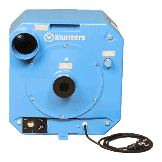
- Page 1 Original instructions User manual M120 Desiccant dehumidifier 190TGB-1008-H1402 © Munters Europe AB 2014...
-
Page 2: Warranty
Important user information Intended use Safety Munters dehumidifiers are intended to be used for the Information about dangers are in this manual indicated dehumidification of air. Any other use of the unit, or by the common hazard symbol: use which is contrary to the instructions given in this... -
Page 3: Table Of Contents
Safety ........10 Contact Munters ...... -
Page 4: Introduction
Read through the manual before the dehumidifier is installed and used. Contact your nearest Munters office if you have any questions regarding the installation or the use of your dehumidifier. -
Page 5: Safety
- Do not insert fingers or any other objects into the air vents, rotating fans are inside. - Do not cover the unit as that can block air intake or outlet and cause a fire. - If the unit has overturned, cut the power immediately. - Always contact Munters for service or repair. Introduction 190TGB-1008-H1402... -
Page 6: Marking
M120 1.4 Marking Type M120 Fa br. No. 0826 170XXX XXXXX Fa br. ye a r 2008 We ig h t: 26 kg 230V 50 Hz 0,1 kW 1,2 kW Ma x 1,3 kW IP 44 Ma d e in S we d e n... -
Page 7: Dehumidifier Design
M120 2 Dehumidifier design 2.1 Product description The dehumidifier is designed to efficiently dehumidify air. Its very compact construction incorporates sections held together by four bolts. The sections contain fans that are driven by a common motor, a direct gear driven desiccant rotor and a reactivation airflow heater. -
Page 8: Transport, Inspection And Storage
4. Remove all packaging material from the unit, and make sure that no damage has occurred during transportation. 5. Any visible damage must be reported in writing to Munters within 5 days and prior to installation of the unit. 6. Dispose of the packaging material according to local regulations. -
Page 9: Installation
Do not sit, stand, or place any objects on the unit. 4.2 Site requirements The M120 is intended for indoor installation. The unit should be placed in an upright position horizontally standing on fixing lugs on a level surface. Suitable wall bracket (article no. 19030113) or floor foundation fittings (article no. -
Page 10: Connection Of Ducts And Hoses
M120 NOTE! It is important that the intended installation site meets the requirements in order to achieve the best possible performance and trouble-free operation. NOTE! Check that the unit is level after the complete installation. If required the unit can be bolted to the floor using the fixing holes in the bottom of the unit. - Page 11 M120 Figure 4.4 Required duct works, side view Figure 4.5 Required duct works, front view 1 - Dry air A - Wire screen mesh approx. 10 mm 2 - Reactivation air B - Removable rubber sleeve 3 - Wet air...
-
Page 12: Electrical Connections
M120 4.4 Electrical connections Included with the delivery is a 2.5 m long power cable with a plug for connection to an earthed outlet. The voltage and frequency are specified on the unit identification plate, see section 1.4, Marking. 4.5 Continuous fan operation If continuous fan operation is required remove the cover plate to the right of the humidistat socket, see Figure 4.6 . - Page 13 M120 Figure 4.7 Connection of leads and humidistat connection kit assembly A - Lead connections B - Screen connections 1. Connect the leads to pins 1 and 2, and the screen to the earth pin. Lead connections 2. Affix the terminal (2) to the plug (1) 3.
-
Page 14: Reactivation Airflow Adjustment
M120 4.7 Reactivation airflow adjustment Estimate the pressure drop in the duct system for reactivation and wet air according to the following: Each metre length of Ø 80 mm duct gives a pressure drop of 1.0 Pa (0.1mm wg). ■... - Page 15 M120 Figure 4.9 Reactivation airflow as a function of the pressure drop over the orifice plate (shaded area=permitted area). Installation 190TGB-1008-H1402...
-
Page 16: Operation
M120 5 Operation 5.1 Safety W W W ARNING! ARNING! ARNING! Do not operate the unit if the power plug or cord is damaged. Do not insert fingers or any other objects into the air vents. The unit can restart automatically without warning following a power failure. -
Page 17: Automatic Operation
M120 5.2.2 Automatic operation Set the MAN-AUT selector switch to position AUT. 5.3 Stop the unit To stop the unit, disconnect it from the power source or use the external circuit breaker. Operation 190TGB-1008-H1402... -
Page 18: Service And Maintenance
NOTE! It is recommended to contact Munters for service or repair. Operating faults can occur if the unit is maintained insufficiently or incorrectly. Munters Service can offer a service plan adapted to suit the conditions of a specific installation. See contact addresses on the back page of this manual. -
Page 19: Filter Replacement
M120 6.3 Filter replacement A. Screw B. Cover C. Grating D. Retainer E. Filter (article no. 19013498) F. Fan inlet cone Figure 6.1 Filter assembly (reactivation side) 1. Remove the screws (A) holding the cover. 2. Remove the cover (B) and take out the filter cassette (C, D, E). -
Page 20: Fault Tracing
M120 7 Fault tracing Fault symptom Possible Cause Corrective action Unit has stopped. Failure of the electrical supply Check power supply to the unit . The thermostat on the heater has tripped Press the reset button on the thermal cut-out after removing the... -
Page 21: Technical Specification
M120 8 Technical specification 8.1 Dimensions and service space Service- Width (A) Width (B) Height (C) Diam. (D) Diam. (E) Weight space (F) 425 mm 481 mm 425 mm 100 mm 80 mm 1000 mm 26 kg Table 8.1 Dimension and weight... -
Page 22: Capacity Diagram
M120 8.2 Capacity diagram Approximate capacity in kg/h. For detailed information, please contact your nearest Munters location. 1. Temperature, process air (°C) 80 % 2. Relative Humidity, process air ( % RH) 60 % 3. Dehumidification capacity (kg/h) 40 % (moisture removal (kg/hour) Figure 8.1 Capacity diagram... -
Page 23: Technical Data
M120 8.3 Technical data Process air Free-blowing air 50 Hz (m³/h) Free-blowing air 60 Hz (m³/h) Rated airflow (m³/h) Available static pressure 50 Hz (Pa) Available static pressure 60 Hz (Pa) Fan motor power (kW) 0,030 Reactivation air Rated airflow (m³/h) -
Page 24: Sound Data
M120 8.4 Sound data Correction Kok dB at ISO-band centre frequency, Hz Noise path dB(A)* 1000 2000 4000 8000 Table 8.3 Sound data SYMBOLS: = Total noise level dB (rel. 10 = Noise power level in octave band dB (rel. 10... -
Page 25: Scrapping
M120 9 Scrapping The unit must be scrapped in accordance with applicable legal requirements and regulations. Contact your local authorities. The rotor material is not combustible, and should be deposited like glass fibre materials. If the rotor has been exposed to chemicals that are dangerous to the environment the risk must be assessed. -
Page 27: Contact Munters
Energieweg 69 Tel: +31 172 43 32 31 NL-2404 HE Alphen a/d Rijn vochtbeheersing@munters.nl www.munters.nl Tel.: + 48 58 305 35 17 POLAND Munters Sp. z o.o. ul. Swietojanska 55/11 Oddzial w Polsce 81-391 Gdynia dh@munters.pl Air Treatment www.munters.com.pl SPAIN Munters Spain SA Europa Epresarial. - Page 28 www.munters.com...
Need help?
Do you have a question about the M120 and is the answer not in the manual?
Questions and answers