Table of Contents
Advertisement
Advertisement
Table of Contents

Related Manuals for Munters ML420


Summary of Contents for Munters ML420
- Page 1 ENGLISH Dehumidifier ML420-1350, MLT800-1400 User manual T-ML2-A1904...
- Page 2 Copyright © 2019 Munters Europe AB Original instructions Valid for units produced from April 2019. IMPORTANT Read these instructions before using the product.
-
Page 3: Table Of Contents
Dehumidifier ML420-1350, MLT800-1400 Table of Contents 1. Important user information ....................5 1.1. Intended use ......................5 1.2. Warranty ......................... 5 1.3. Safety information ....................5 1.4. Copyright ........................ 6 2. Introduction ........................7 2.1. About this manual ....................7 2.2. - Page 4 Dehumidifier ML420-1350, MLT800-1400 9.4. Sound data ......................30 9.4.1. Definition ....................30 9.4.2. Sound data ML420 ..................31 9.4.3. Sound data ML690 ..................31 9.4.4. Sound data MLT800 ................... 32 9.4.5. Sound data ML1100 ..................32 9.4.6. Sound data ML1350 ................... 33 9.4.7.
-
Page 5: Important User Information
1.2. Warranty The warranty is based on the terms of sale and delivery of Munters. The warranty is not valid if repairs or modifications are carried out without the written agreement of Munters, or if the unit does not operate under the conditions agreed with Munters. -
Page 6: Copyright
The contents of this manual can be changed without prior notice. NOTE This manual contains information which is protected by copyright laws. It is not allowed to reproduce or transmit any part of this manual without written consent from Munters. Munters Europe AB, P.O. Box 1150, SE-16426 KISTA Sweden... -
Page 7: Introduction
Read through the manual before the dehumidifier is installed and used. Contact your nearest Munters office if you have any questions about the installation or the use of your dehumidifier. - Page 8 Dehumidifier ML420-1350, MLT800-1400 WARNING • All electrical installations must be done by an authorized electrician in accordance with local regulations. An incorrect installation can cause electrical shock hazards and damage to the unit. • Commissioning and initial start-up of the unit must be done by authorized personnel only.
-
Page 9: Marking
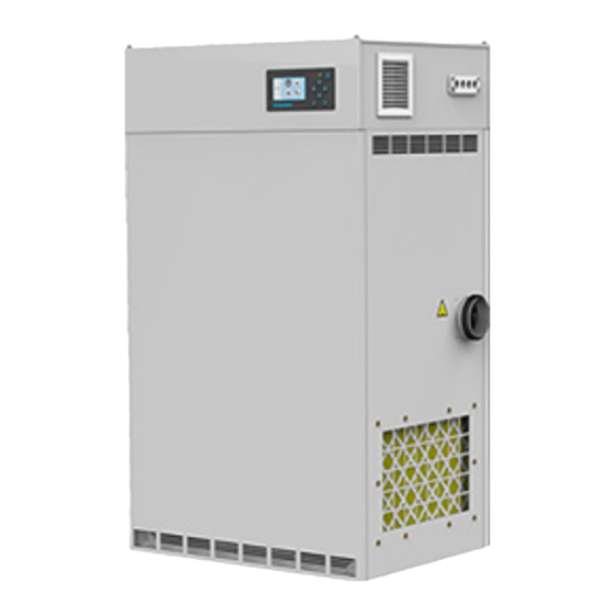
Dehumidifier ML420-1350, MLT800-1400 2.4. Marking 1. Unit identification plate 2. Dry air outlet 3. Wet air outlet 4. Process air inlet 5. Reactivation air inlet Example identification plate. The first four digits in the fabrication number indicate year and week (YYWW) of production for the unit. -
Page 10: Dehumidifier Design
Dehumidifier ML420-1350, MLT800-1400 3. Dehumidifier design 3.1. Product description The desiccant dehumidifiers in the ML series have been developed to effectively dehumidify the air in environments requiring low air humidity. The dehumidifier is equipped with an encapsulated rotor unit. The rotor casing is constructed of durable thermoset plastic and contains isolated sections that provide a precise balance for the dehumidification, reactivation and heat recovery airflows. -
Page 11: Main Components
Upper rotor cover Process air filter NOTE The ML420 unit has only one fan motor that is placed between the process and reacti- vation impellers. 3.4. Insulated process air inlet When cold process air is to be dehumidified, often in conjunction with a pre-cooler, condensate will readily form on the inlet side of the dehumidifier. -
Page 12: Transport, Delivery Inspection And Storage
• Any damage to the unit must be documented with photos. • Any visible damage must be reported in writing to Munters within 3 days and prior to installation of the unit. • Discard the packaging material according to local regulations. -
Page 13: Installation
It is important for maintenance purposes to obey the minimum service space require- ments. The dehumidifier is only intended for indoor installation. For space requirements, see section Dimensions and service space. NOTE If there is a need for reduction of vibrations from the dehumidifier, contact Munters for instructions. -
Page 14: Foundation
Dehumidifier ML420-1350, MLT800-1400 5.3. Foundation The dehumidifier must be installed on a level floor, or platform, which has been designed with a floor loading capacity capable of supporting the total weight of the unit. If the maximum floor loading weight is not exceeded, special foundations are not required. - Page 15 Dehumidifier ML420-1350, MLT800-1400 • The ducts must always be insulated when there is a risk of freezing. • The wet air leaving the dehumidifier will, because of high moisture content, condense on the inside duct walls. By insulating the ducts, the amount of condensate is reduced.
-
Page 16: Duct For Outdoor Air Inlet
Dehumidifier ML420-1350, MLT800-1400 5.4.2. Duct for outdoor air inlet When bringing outside ambient air into the dehumidifier, the opening to the inlet duct should be located sufficiently high above ground level to prevent the pick up of dust and debris. The ducting should be designed to prevent rain and snow from being drawn into the dehumidifier. -
Page 17: Precautionary Measures For Units With Lithium Chloride Rotor
5.5. Precautionary measures for units with lithium chloride rotor The standard delivery is Munters high performance desiccant rotor HPS (High Performance Silica gel). If the dehumidifier is delivered with an LI rotor (lithium chloride) it is important that the rotor does not become loaded with moisture when the dehumidifier is off. -
Page 18: External Humidity Sensor
Dehumidifier ML420-1350, MLT800-1400 NOTE If the unit is connected to the power after an RCD (Residual Current Device), also known as an earth fault breaker, this must be of “industrial” type B typically with a sen- sitivity of 100 mA or greater to avoid any unwanted tripping. -
Page 19: Commissioning
Rotating fan blades can cause serious injury. Only operate the unit with the air ducts connected. CAUTION The airflows must never be set above the rated airflows without consulting Munters for verification. CAUTION Incorrect adjustment of the airflows can cause malfunction of the unit. Any damage to the unit resulting from incorrect adjustment of the airflows can invalidate the warranty of the unit. -
Page 20: Function Test
To obtain optimal performance, the process and reactivation airflows must be correctly adjusted. Contact Munters for help with installation and settings. 1. Adjust the dampers installed in the dry air outlet and reactivation air inlet ducts to the correct rated airflows. -
Page 21: Operation
Dehumidifier ML420-1350, MLT800-1400 7. Operation 7.1. Main power switch SIEMENS Main power switch • When the main power switch is set to position O, the unit is not powered beyond the switch. • When the main power switch is set to position 1, the unit is powered and can be started. -
Page 22: Start/Stop From Control System Panel
Dehumidifier ML420-1350, MLT800-1400 7.3.1. Start/stop from control system panel Press the start/stop button in the upper right corner to operate the unit. • From Off, press once to go to Automatic mode, with sensor control. • From Off or Automatic, press and hold for more than 3 seconds to go to Manual mode, 100% capaci- ty dehumidification. -
Page 23: Service And Maintenance
More information can be obtained from the local Munters representative. 8.3. Extended warranty Munters offers an extended warranty to the standard terms when the Customer signs a service agree- ment with Munters. Details are available on request. 8.4. Service alternatives In addition to commissioning (S) of the unit there are four service alternatives (A - D) as standard. -
Page 24: Maintenance Schedule
Dehumidifier ML420-1350, MLT800-1400 NOTE It is recommended to contact Munters for service or repair. Operating faults can occur if the unit is maintained insufficiently or incorrectly. 8.5. Maintenance schedule Service alterna- tive Operating time [hours] Calendar time [months] Inspection of fil-... -
Page 25: Preventive Replacements
Use only a pH-neutral soapy water solution and a soft sponge for cleaning of the unit casing. When cleaning the inside, avoid contact with the rotor and wipe the surfaces dry. Use a vacuum cleaner with a brush head for the rotor. Contact Munters for instructions if vacuum clean- ing is not sufficient. -
Page 26: Technical Specification
Dehumidifier ML420-1350, MLT800-1400 9. Technical specification 9.1. Dimensions and service space ØD ØE ØF Dimensions (IPI version to the right) 1. Process air 2. Dry air 3. Reactivation air 4. Wet air Minimum required service space and screw pattern for duct connection... -
Page 27: Capacity Diagrams
Dehumidifier ML420-1350, MLT800-1400 9.2. Capacity diagrams Approximate capacity in kg/h. Contact Munters for more detailed information. NOTE The below figures are based on rated airflow. 1. Process air temperature (°C) 2. Process air relative humidity (% RH) 3. Dehumidification capacity (moisture removal per hour) (kg/h) - Page 28 Dehumidifier ML420-1350, MLT800-1400 kg/h kg/h 15.0 15.0 ML1350 MLT1400 12.5 12.5 10.0 10.0...
-
Page 29: Technical Data
Dehumidifier ML420-1350, MLT800-1400 9.3. Technical data Model ML420 ML690 MLT800 ML1100 ML1350 MLT1400 Process air Rated airflow (m 0,116 0,192 0,222 0,305 0,375 0,388 Rated airflow (m 1100 1350 1400 Available static pressure (Pa) Fan motor power (kW) at 50... -
Page 30: Sound Data
Figures quoted are based on fan inlet temperature of 20°C, and an air density of 1,2 kg/m Without optional F5 or F7 filter boxes. ML420 dehumidifiers have a single motor driving both process air and reactivation air fans. Contacts used to give an external indication (output). -
Page 31: Sound Data Ml420
Dehumidifier ML420-1350, MLT800-1400 9.4.2. Sound data ML420 Table 1. Sound to room, all inlets and outlets ducted Lp(A) at Lw(A) Measure range 1000 2000 4000 8000 dB(A) Table 2. Sound in ducts Duct Lw(A) Measure range 1000 2000 4000 8000 dB(A) 9.4.3. -
Page 32: Sound Data Mlt800
Dehumidifier ML420-1350, MLT800-1400 9.4.4. Sound data MLT800 Table 5. Sound to room, all inlets and outlets ducted Lp(A) at Lw(A) Measure range 1000 2000 4000 8000 dB(A) Table 6. Sound in ducts Duct Lw(A) Measure range 1000 2000 4000 8000 dB(A) 9.4.5. -
Page 33: Sound Data Ml1350
Dehumidifier ML420-1350, MLT800-1400 9.4.6. Sound data ML1350 Table 9. Sound to room, all inlets and outlets ducted Lp(A) at Lw(A) Measure range 1000 2000 4000 8000 dB(A) Table 10. Sound in ducts Duct Lw(A) Measure range 1000 2000 4000 8000 dB(A) 9.4.7. -
Page 34: Disposal
Dehumidifier ML420-1350, MLT800-1400 10. Disposal The unit and consumables must be disposed of in accordance with applicable legal requirements and regulations. Contact your local authorities. If the rotor or filters have been exposed to chemicals that are dangerous to the environment the risk must be assessed. -
Page 35: Contact Munters
Dehumidifier ML420-1350, MLT800-1400 11. Contact Munters EUROPE AUSTRIA Tel: +43 1 616 4298-92 51 ITALY Tel: +39 0183 521377 luftentfeuchtung@munt- marketing@munters.it ers.at BELGIUM Tel: +3215285611 NETHER- Tel: +31 172 43 32 31 LANDS service@muntersbel- vochtbeheersing@munters.nl gium.be CZECH REPUB- Tel: +420 775 569 657 POLAND Tel.: + 48 58 305 35 17... - Page 36 www.munters.com...
Need help?
Do you have a question about the ML420 and is the answer not in the manual?
Questions and answers