
Related Manuals for Munters MCS300


Summary of Contents for Munters MCS300
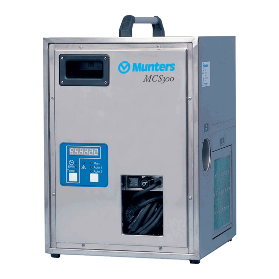
- Page 1 Original instructions User manual MCS300 Desiccant dehumidifier 190TEN-1027-G1606 © Munters Europe AB 2016...
-
Page 2: Important User Information
Important user information Intended use Safety Munters dehumidifiers are intended to be used for the Information about dangers are in this manual indicated dehumidification of air. Any other use of the unit, or by the common hazard symbol: use which is contrary to the instructions given in this... -
Page 3: Table Of Contents
Electrical connections ....13 Contact Munters ...... -
Page 4: Introduction
Read through the manual before the dehumidifier is installed and used. Contact your nearest Munters office if you have any questions regarding the installation or the use of your dehumidifier. -
Page 5: Safety
- Do not insert fingers or any objects into the air vents, rotating fans are inside. - Do not cover the unit as that can block air intake or outlet and cause a fire. - If the unit has overturned, cut the power immediately. - Always contact Munters for service or repair. Introduction 190TEN-1027-G1606... -
Page 6: Marking
MCS300 1.4 Marking Type Fabr. No Munters Europe AB Tobo Sweden Figure 1.1 Identification plate position Introduction 190TEN-1027-G1606... -
Page 7: Function Overview
MCS300 2 Function overview The desiccant rotor is the adsorption dehumidifying component in the unit. The rotor structure is comprised of a large number of small air channels. The desiccant rotor is made of a composite material that is highly effective in attracting and retaining water vapour. -
Page 8: Transport, Inspection And Storage
Remove all packaging material from the unit, and make sure that no damage has been made during ■ transportation. Any visible damage must be reported in writing to Munters within 3 days and prior to installation of ■ the unit. -
Page 9: Installation
- Do not insert fingers or any objects into the air vents, rotating fans are inside. - Do not cover the unit as that can block air intake or outlet and cause a fire. - If the unit has overturned, cut the power immediately. - Always contact Munters for service or repair. CA UTION! UTION! UTION! Do not sit, stand, or place any objects on the unit. -
Page 10: Site Requirements
Avoid installing the dehumidifier where there is a risk of water entering the unit, or in a very dusty environment. Refer to Munters for advice if in doubt. For unit and service dimensions, see section 11, Technical specification. NOTE! It is important that the intended installation site meets the requirements in order to achieve the best possible performance and trouble-free operation. -
Page 11: Closed Airflow System
MCS300 4.4.2 Closed airflow system The dehumidifier is placed in the space to be dehumidified. The wet air is transported outdoors with ducting. The performance can be improved with an optional dry air duct and damper. Figure 4.2 Closed airflow system. -
Page 12: Open Airflow System
MCS300 4.4.3 Open airflow system The dehumidifier is placed outside the area to be dehumidified. Dry air is transported with ducting to the space to be dehumidified and the wet air is discharged in the vicinity of the unit or moved outdoors. -
Page 13: Electrical Connections
MCS300 4.5 Electrical connections Included with the delivery is a 3.5 m long power cable with a plug for connection to an earthed outlet. W W W ARNING! ARNING! ARNING! The unit must be connected to an earthed electrical outlet. -
Page 14: Humidistat Connection Kit
MCS300 4.6.2 Humidistat connection kit Follow the instructions below to assemble and connect the humidistat connection kit. 1. Connect the leads to pins 1 and 2, and the screen to the earth pin. Figure 4.6 Connection of leads A. Lead connections B. -
Page 15: Operation
MCS300 5 Operation 5.1 General W W W ARNING! ARNING! ARNING! Pull the power cable out from the cable compartment before operating the dehumidifier to avoid overheating. The dehumidifier has three operating modes, see Figure 5.1 . Man: The dehumidifier’s fans, rotor and reactivation heater operate continuously. -
Page 16: Start
MCS300 5.3 Start 5.3.1 Measured values Auto 1 C. Measurement selector Temp Auto 2 D. Operating mode selector Figure 5.2 Control panel The following parameter information is displayed on the control panel: Total operating time Power consumption during a specific period Reactivation temperature Change the parameter display by pressing the measurement selector button on the control panel. -
Page 17: Stop
MCS300 2. Adjust the humidistat to the desired setpoint. 3. Switch the on-off switch to position I, see Figure 5.1 . 4. Select the Auto 1 or 2 operating mode by pressing the operating mode selector button, see Figure 5.1 . -
Page 18: Service And Maintenance
NOTE! It is recommended to contact Munters for service or repair. Operating faults can occur if the unit is maintained insufficiently or incorrectly. Munters Service can offer a service plan adapted to suit the conditions of a specific installation. See contact addresses on the back page of this manual. -
Page 19: Filter Replacement
MCS300 6.3 Filter replacement Figure 6.1 Filter removal 1. To remove the filter, slide the filter grating upwards, then downwards and out according to Figure 6.1 . 2. Clean filter housing and grating before fitting the new filter. Service and maintenance... -
Page 20: Fault Tracing
MCS300 7 Fault tracing 7.1 General This chapter is intended to facilitate basic fault tracing and provide instructions on actions to remedy problems. 7.2 Safety W W W ARNING! ARNING! ARNING! Always unplug the dehumidifier before any maintenance or repair work is carried out. In case of a fixed installation where the plug is being replaced by a circuit breaker, the power must be switched off and the circuit breaker locked. -
Page 21: Fault Tracing List
MCS300 7.3 Fault tracing list Go through the following fault tracing list below before contacting Munters’ product service department. The list provides help in identifying types of faults that are easy to remedy without the assistance of specially trained personnel... -
Page 22: Capacity Diagrams
MCS300 8 Capacity diagrams Approximate capacity in kg/h. For detailed information, please contact your nearest Munters office or refer to Munters’ DryCap program. kg/h 230V, 50 H z 80 % R H 60 % R H 40 % R H °C... -
Page 23: Fan Diagrams
MCS300 9 Fan diagrams Figure 9.1 Fan diagrams (115/230V, 50 Hz) 115V/ 60 H z Figure 9.2 Fan diagrams (115V, 60 Hz) A. Static pressure (Pa) C. Process air B. Airflow m D. Reactivation air Fan diagrams 190TEN-1027-G1606... -
Page 24: Sound Data
MCS300 10 Sound data See Figure 4.2 for closed airflow system example. Correction of Kok at ISO-band No./Center Frequency (Hz) Noise Model dB(A) Path 1/63 2/125 3/250 4/500 5/1000 6/2000 7/4000 8/8000 69,3 -23,8 -11,7 -9,9 -10,5 -17,5 -19,3 -22,3... -
Page 25: Technical Specification
MCS300 11 Technical specification Technical data MCS300 230V/50 Hz 115V/50 Hz 115V/60 Hz Process air System airflow (m³/h) Nominal airflow with ducting (m³/h) Minimum available static pressure (Pa) Reactivation air Nominal airflow with ducting (m³/h) Minimum available static pressure (Pa) -
Page 26: Scrapping And Disposal
MCS300 12 Scrapping and disposal The unit must be scrapped in accordance with applicable legal requirements and regulations. Contact your local authorities. If the rotor or filters have been exposed to chemicals that are dangerous to the environment the risk must be assessed. -
Page 27: Contact Munters
BELGIUM Munters Belgium nv Blarenberglaan 21c Tel: +3215285611 Air Treatment B-2800 Mechelen service@muntersbelgium.be www.muntersbelgium.be CZECH REPUBLIC Munters CZ, organizacni slozka Slevacská 2368/68 Tel: +420 775 569 657 info@munters-odvlhcovani.cz Air Treatment CZ-615 00 BRNO www.munters-odvlhcovani.cz DENMARK Ryttermarken 4 Tel: +4544953355... - Page 28 www.munters.com...
Need help?
Do you have a question about the MCS300 and is the answer not in the manual?
Questions and answers