Advertisement
Quick Links
www.ti.com
EVM User's Guide: TPS22996EVM
TPS22996 Evaluation Module
Description
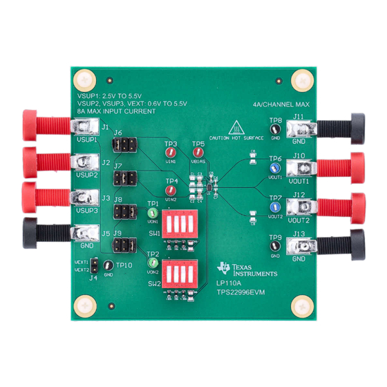
The TPS22996EVM is a four-layer PCB containing
the TPS22996 dual-channel load switch device. The
VIN and VOUT connections to the device and the
PCB layout routing are capable of handling high
continuous currents and provide a low-resistance
pathway into and out of the device under test.
TPS22996EVM allows for accurate measurement of
the TPS22996 device while also providing an easy
interface for the user to evaluate the novel features.
SLVUCP0 – DECEMBER 2023
Submit Document Feedback
Features
•
V
IN
•
V
BIAS
•
Access to the V
of the TPS22996 load switch device
•
Onboard C
•
Onboard ON resistors for setting V
•
4-A maximum continuous current per channel
Applications
•
PC and notebooks
•
Set-top boxes and residential gateways
•
Telecom systems
•
Solid-state drives (SSD)
Copyright © 2023 Texas Instruments Incorporated
input voltage range: 0.6 V to V
input voltage range: 2.5 V to 5.5 V
, V
, ON, V
IN
OUT
and C
capacitors
IN
OUT
TPS22996 Evaluation Module
Description
BIAS
, and GND pins
BIAS
slew rate
OUT
1
Advertisement

Related Manuals for Texas Instruments TPS22996EVM


Summary of Contents for Texas Instruments TPS22996EVM
- Page 1 Description EVM User's Guide: TPS22996EVM TPS22996 Evaluation Module Description Features The TPS22996EVM is a four-layer PCB containing • input voltage range: 0.6 V to V BIAS the TPS22996 dual-channel load switch device. The • input voltage range: 2.5 V to 5.5 V...
- Page 2 EVM. 1.2 Kit Contents Kit Contents lists the contents of the EVM kit. Contact the Texas Instruments Product Information Center nearest you if any components are missing. TI highly recommends that users check the TI website at https://www.ti.com to verify that the latest versions of the related software is being used.
- Page 3 Table 2-2 describes the different test points and functionality. Table 2-3 describes the jumper functionality and configurations. Table 2-1. TPS22996EVM Input and Output Connector Functionality Connector and Test Input Label Description Point...
- Page 4 See the TPS22996 5.5V, 4-A, 14 mΩ On-Resistance Dual-Channel Load Switch data sheet (SLVSH99) for detailed electrical characteristics of the TPS22996. 3.2 Test Configurations 3.2.1 Rise Time Test Setup Figure 3-1. TPS22996 Rise Time Test Setup TPS22996 Evaluation Module SLVUCP0 – DECEMBER 2023 Submit Document Feedback Copyright © 2023 Texas Instruments Incorporated...
- Page 5 TP10 SW1D 1.00M 76SB04ST SW2A VSUP1 VSUP2 180k 76SB04ST VEXT2 SW2B HTSW-103-07-G-D VON2 28.0k 76SB04ST SW2C 4.99k 76SB04ST SW2D 1.00M 76SB04ST Figure 4-1. Schematic SLVUCP0 – DECEMBER 2023 TPS22996 Evaluation Module Submit Document Feedback Copyright © 2023 Texas Instruments Incorporated...
- Page 6 Hardware Design Files www.ti.com 4.2 PCB Layout Figure 4-2. PCB Top Figure 4-3. PCB Bottom TPS22996 Evaluation Module SLVUCP0 – DECEMBER 2023 Submit Document Feedback Copyright © 2023 Texas Instruments Incorporated...
- Page 7 TP6, TP7 Test Point, Multipurpose, Blue, TH 5127 Keystone Electronics Testpoint Black Multipurpose TP8, TP9, TP10 Test Point, Multipurpose, Black, TH 5011 Keystone Electronics Testpoint SLVUCP0 – DECEMBER 2023 TPS22996 Evaluation Module Submit Document Feedback Copyright © 2023 Texas Instruments Incorporated...
- Page 8 CAP, CERM, 10 µF, 16 V,+/- 10%, X7R, 0805 0805 CL21B106KOQNNNG Samsung RES, 1.00 M, 1%, 0.125 W, AEC-Q200 Grade R4, R8 1.00Meg 0805 ERJ-6ENF1004V Panasonic 0, 0805 TPS22996 Evaluation Module SLVUCP0 – DECEMBER 2023 Submit Document Feedback Copyright © 2023 Texas Instruments Incorporated...
- Page 9 Additional Information 5 Additional Information Trademarks All trademarks are the property of their respective owners. SLVUCP0 – DECEMBER 2023 TPS22996 Evaluation Module Submit Document Feedback Copyright © 2023 Texas Instruments Incorporated...
- Page 10 STANDARD TERMS FOR EVALUATION MODULES Delivery: TI delivers TI evaluation boards, kits, or modules, including any accompanying demonstration software, components, and/or documentation which may be provided together or separately (collectively, an “EVM” or “EVMs”) to the User (“User”) in accordance with the terms set forth herein.
- Page 11 www.ti.com Regulatory Notices: 3.1 United States 3.1.1 Notice applicable to EVMs not FCC-Approved: FCC NOTICE: This kit is designed to allow product developers to evaluate electronic components, circuitry, or software associated with the kit to determine whether to incorporate such items in a finished product and software developers to write software applications for use with the end product.
- Page 12 www.ti.com Concernant les EVMs avec antennes détachables Conformément à la réglementation d'Industrie Canada, le présent émetteur radio peut fonctionner avec une antenne d'un type et d'un gain maximal (ou inférieur) approuvé pour l'émetteur par Industrie Canada. Dans le but de réduire les risques de brouillage radioélectrique à...
- Page 13 www.ti.com EVM Use Restrictions and Warnings: 4.1 EVMS ARE NOT FOR USE IN FUNCTIONAL SAFETY AND/OR SAFETY CRITICAL EVALUATIONS, INCLUDING BUT NOT LIMITED TO EVALUATIONS OF LIFE SUPPORT APPLICATIONS. 4.2 User must read and apply the user guide and other available documentation provided by TI regarding the EVM prior to handling or using the EVM, including without limitation any warning or restriction notices.
- Page 14 Notwithstanding the foregoing, any judgment may be enforced in any United States or foreign court, and TI may seek injunctive relief in any United States or foreign court. Mailing Address: Texas Instruments, Post Office Box 655303, Dallas, Texas 75265 Copyright © 2023, Texas Instruments Incorporated...
- Page 15 TI products. TI’s provision of these resources does not expand or otherwise alter TI’s applicable warranties or warranty disclaimers for TI products. TI objects to and rejects any additional or different terms you may have proposed. IMPORTANT NOTICE Mailing Address: Texas Instruments, Post Office Box 655303, Dallas, Texas 75265 Copyright © 2023, Texas Instruments Incorporated...
Need help?
Do you have a question about the TPS22996EVM and is the answer not in the manual?
Questions and answers