Table of Contents
Advertisement
Quick Links
www.ti.com
EVM User's Guide: TPS2HCS10-Q1
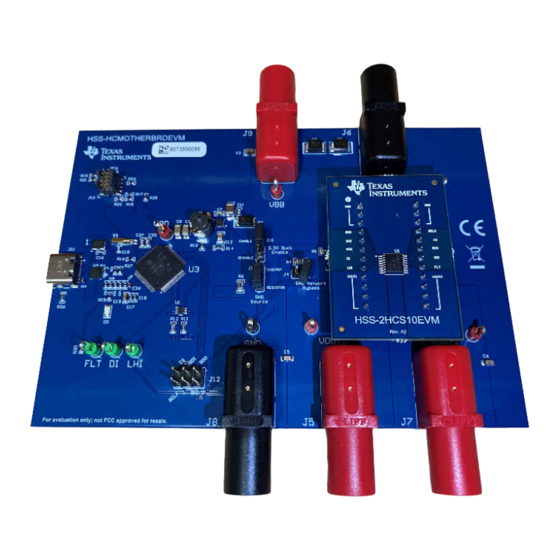
Smart Fuse Evaluation Module
Description
The HSS-HCMOTHERBRDEVM and corresponding
daughter cards (such as the HSS-2HCS10EVM)
are used to showcase and evaluate all features of
the Texas Instruments' smart fuse high-side switch
portfolio. The motherboard is designed to be used
with several different daughter cards enabling the use
of a single host EVM for a variety of different high-side
switches with varying on-resistances and functionality.
A pre-flashed MCU is included with each HSS-
HCMOTHERBOARDEVM to act as a USB-to-SPI
bridge and allow the user to seamlessly configure/
manipulate the device. This MCU communicates
with a Windows
®
host GUI application titled Smart
Fuse Configurator to allow for full configuration and
evaluation of the attached high-side switch.
Get Started
1. Order both the HSS-HCMOTHERBRDEVM and
an accompanying daughter card (such as the
HSS-2HCS10EVM) on ti.com.
2. Plug the daughter card into the socket of the
motherboard aligning the dots to signify pin 1.
3. Connect a power supply to the VBB line (J9) and
connect the ground of the power supply to the
ground line of the board.
4. Connect the relevant loads to the outputs of the
board (J5 and J7).
5. Download the Smart Fuse Configurator from the
EVM product
page.
1
The daughter cards and mother boards have two separate orderable numbers.
SLVUCR9A – AUGUST 2023 – REVISED OCTOBER 2023
Submit Document Feedback
6. Open the Smart Fuse Configurator host program
Features
•
•
•
•
1
Applications
•
•
•
Copyright © 2023 Texas Instruments Incorporated
and use as described in this document.
Daughter Card Socket - Modular daughter card
design allowing to use any TI smart fuse high-side
switch via the same motherboard EVM
TM4C123GH6 32-bit Arm Cortex-M4F based MCU
- Used as a USB to SPI host from the host PC to
the attach high-side switch daughter card
– 9-pin Cortex-M JTAG port allows for users
to program/debug their own firmware to the
TM4C123
LMR43610-Q1 Automotive 3-V to 36-V, 1-A, low-
EMI synchronous buck regulator - Uses the supply
voltage to derive 3.3V power rail to supply VDD of
high-side switch
– Can be disabled via jumper setting if external
VDD source is desired
Test Points - Fully accessible test-points/headers
allowing complete access to SPI lines, fault
signals, power rails
Automotive Zone ECU
Power Distribution Modules
Body control modules
Smart Fuse Evaluation Module
Description
1
Advertisement
Table of Contents

Related Manuals for Texas Instruments TPS2HCS10-Q1


Summary of Contents for Texas Instruments TPS2HCS10-Q1
- Page 1 • Daughter Card Socket - Modular daughter card the Texas Instruments' smart fuse high-side switch design allowing to use any TI smart fuse high-side portfolio. The motherboard is designed to be used...
-
Page 2: Kit Contents
The HSS-HCMOTHERBRDEVM and accompanying daughter card EVMs (such as the HSS-2HCS10EVM) are hardware evaluation boards used for evaluation and development of Texas Instruments’ smart fuse high-side switch portfolio. A daughter card and motherboard approach is used in the hardware ecosystem to promote reuse of hardware and software, as well showcase the pin compatibility between different smart fuse devices. -
Page 3: Device Information
EVM is built for evaluation with ample test points, the EVM is not optimized for EMC testing and performance including emissions, RF, and transient immunity tests. 1.4 Device Information The HSS-HCMOTHERBRDEVM and daughter cards uses the following devices from Texas Instruments. Table 1-1. Devices Used Device Name... - Page 4 • Texas Instruments Smart Fuse Configurator software tool (4MB). No special drivers or large proprietary frameworks are needed to run the Smart Fuse Configurator. To get started, plug the daughter card into the headers marked J1 and J2 on the HSS-HCMOTHERBRDEVM as seen below.
- Page 5 With the device powered, open the auto_hss_configurator.exe executable that ships with the Smart Fuse Configurator software package. Note that the software package from TI.com is a portable zip file and does SLVUCR9A – AUGUST 2023 – REVISED OCTOBER 2023 Smart Fuse Evaluation Module Submit Document Feedback Copyright © 2023 Texas Instruments Incorporated...
- Page 6 GUI a message is displayed in the status bar. A timestamped list of all previous events can be seen in the Log tab as seen below. Smart Fuse Evaluation Module SLVUCR9A – AUGUST 2023 – REVISED OCTOBER 2023 Submit Document Feedback Copyright © 2023 Texas Instruments Incorporated...
- Page 7 The detailed usage guide for each of the tabs in the software can be found in the sections below. SLVUCR9A – AUGUST 2023 – REVISED OCTOBER 2023 Smart Fuse Evaluation Module Submit Document Feedback Copyright © 2023 Texas Instruments Incorporated...
-
Page 8: Jumper Information
Probe points for the digital signals of the high-side switch. FLT is an open drain output with a pull-up resistor connected to the MCU's 3.3V rail. Smart Fuse Evaluation Module SLVUCR9A – AUGUST 2023 – REVISED OCTOBER 2023 Submit Document Feedback Copyright © 2023 Texas Instruments Incorporated... - Page 9 Avg setting. In addition to load current, the device can also be configured to graph/report FET temperature and output voltage. This setting is changed through the Source box. SLVUCR9A – AUGUST 2023 – REVISED OCTOBER 2023 Smart Fuse Evaluation Module Submit Document Feedback Copyright © 2023 Texas Instruments Incorporated...
- Page 10 By clicking the sleep mode button, a prompt occurs to warn the user about the state change: Figure 3-3. Enter Sleep Mode Smart Fuse Evaluation Module SLVUCR9A – AUGUST 2023 – REVISED OCTOBER 2023 Submit Document Feedback Copyright © 2023 Texas Instruments Incorporated...
- Page 11 GUI takes the current configuration settings from the GUI and writes them back to the device. Figure 3-5. Settings Restored SLVUCR9A – AUGUST 2023 – REVISED OCTOBER 2023 Smart Fuse Evaluation Module Submit Document Feedback Copyright © 2023 Texas Instruments Incorporated...
- Page 12 This resistor has implications on the I2T trip values populated by the GUI. In addition, the tolerance of the populated resistor can be changed to reflect the translated inaccuracy on the plotted I2T graph. Smart Fuse Evaluation Module SLVUCR9A – AUGUST 2023 – REVISED OCTOBER 2023 Submit Document Feedback Copyright © 2023 Texas Instruments Incorporated...
- Page 13 I2T setting trips on a transient such as a capacitive inrush event. In the Pulse Check box, enable a pulse and input a current/duration. An example of plotting a static current point can be seen below: SLVUCR9A – AUGUST 2023 – REVISED OCTOBER 2023 Smart Fuse Evaluation Module Submit Document Feedback Copyright © 2023 Texas Instruments Incorporated...
- Page 14 In the Complete sub-tab, the user can examine the full fuse current profile as described in the data sheet. Figure 3-10. Full Current Profile Smart Fuse Evaluation Module SLVUCR9A – AUGUST 2023 – REVISED OCTOBER 2023 Submit Document Feedback Copyright © 2023 Texas Instruments Incorporated...
- Page 15 Figure 3-12. Faulted Device View SLVUCR9A – AUGUST 2023 – REVISED OCTOBER 2023 Smart Fuse Evaluation Module Submit Document Feedback Copyright © 2023 Texas Instruments Incorporated...
-
Page 16: Channel Settings
Charging Mode box. Figure 3-13. dv/dt Settings Smart Fuse Evaluation Module SLVUCR9A – AUGUST 2023 – REVISED OCTOBER 2023 Submit Document Feedback Copyright © 2023 Texas Instruments Incorporated... -
Page 17: Console View
The status byte that is returned on a read/write corresponds to the global fault register. See the SPI read/write format section in the data sheet (SLVSGY2) for more information. SLVUCR9A – AUGUST 2023 – REVISED OCTOBER 2023 Smart Fuse Evaluation Module Submit Document Feedback Copyright © 2023 Texas Instruments Incorporated... -
Page 18: Log View
/* TPS2HC10S_I2T_CONFIG_CH1 */ 20,416 /* TPS2HC10S_PWM_CH2 */ 22,1 /* TPS2HC10S_ILIM_CONFIG_CH2 */ 23,0 /* TPS2HC10S_DIAG_CONFIG_CH2 */ 24,0 /* TPS2HC10S_I2T_CONFIG_CH2 */ 28,0 Smart Fuse Evaluation Module SLVUCR9A – AUGUST 2023 – REVISED OCTOBER 2023 Submit Document Feedback Copyright © 2023 Texas Instruments Incorporated... - Page 19 TivaWare installation. This tool can be used to download a binary to the onboard microcontroller of the device. Figure 3-17. dfuprog Invocation SLVUCR9A – AUGUST 2023 – REVISED OCTOBER 2023 Smart Fuse Evaluation Module Submit Document Feedback Copyright © 2023 Texas Instruments Incorporated...
- Page 20 Note in manual refresh mode, the fault diagnostics are automatically set to manual refresh mode in the device settings tab. Smart Fuse Evaluation Module SLVUCR9A – AUGUST 2023 – REVISED OCTOBER 2023 Submit Document Feedback Copyright © 2023 Texas Instruments Incorporated...
-
Page 21: Software Development
The Smart Fuse Configurator comes with a C header file that was generated from the register map of each supported high-side switch. Initially, this includes the TPS2HCS10-Q1 device. The header files are available on the product page and includes functionality such as: •... - Page 22 Software www.ti.com enableReg.byte = 0x01; printf("\nChannel Enable: 0x%x\n", enableReg.byte); return 0; Smart Fuse Evaluation Module SLVUCR9A – AUGUST 2023 – REVISED OCTOBER 2023 Submit Document Feedback Copyright © 2023 Texas Instruments Incorporated...
- Page 23 VOUT2 SCLK SCLK(DIAG_EN) VOUT2 SDI(EN2) VOUT2 SDO(SEL) LHI(ILIM) TPS2HC10SF-Q1 4700pF VOUT1 VOUT2 SCLK Figure 4-1. Daughter Card Schematic (HSS-2HCS10EVM) SLVUCR9A – AUGUST 2023 – REVISED OCTOBER 2023 Smart Fuse Evaluation Module Submit Document Feedback Copyright © 2023 Texas Instruments Incorporated...
- Page 24 TPL0401B-10DCKR 100nF 33.2k 22uF 22uF 4.7µF 9 50V 61103-6804-AR SMBJ36A-13-F LMR43610MSC3RPERQ1 1µF 14.3k SMBJ20A-13-F Figure 4-2. HSS-HCMOTHERBRDEVM (High-Side Switch) Smart Fuse Evaluation Module SLVUCR9A – AUGUST 2023 – REVISED OCTOBER 2023 Submit Document Feedback Copyright © 2023 Texas Instruments Incorporated...
- Page 25 PC0/TCK/SWCLK VDDA 0.1uF 0.1uF XOSC1 XOSC0 24pF 0.1uF 0.01uF 0.1uF 0.01uF 0.1uF GNDX TM4C123GH6PMI7R 24pF Figure 4-3. HSSC-HCMOTHERBRDEVM (MCU) SLVUCR9A – AUGUST 2023 – REVISED OCTOBER 2023 Smart Fuse Evaluation Module Submit Document Feedback Copyright © 2023 Texas Instruments Incorporated...
-
Page 26: Pcb Layouts
Hardware Design Files www.ti.com 4.2 PCB Layouts Figure 4-4. HSS-HCMOTHERBRDEVM Top Layer Smart Fuse Evaluation Module SLVUCR9A – AUGUST 2023 – REVISED OCTOBER 2023 Submit Document Feedback Copyright © 2023 Texas Instruments Incorporated... - Page 27 Hardware Design Files Figure 4-5. HSS-HCMOTHERBRDEVM Power Layer SLVUCR9A – AUGUST 2023 – REVISED OCTOBER 2023 Smart Fuse Evaluation Module Submit Document Feedback Copyright © 2023 Texas Instruments Incorporated...
- Page 28 Hardware Design Files www.ti.com Figure 4-6. HSS-HCMOTHERBRDEVM GND Layer Smart Fuse Evaluation Module SLVUCR9A – AUGUST 2023 – REVISED OCTOBER 2023 Submit Document Feedback Copyright © 2023 Texas Instruments Incorporated...
- Page 29 Hardware Design Files Figure 4-7. HSS-HCMOTHERBRDEVM Bottom Layer SLVUCR9A – AUGUST 2023 – REVISED OCTOBER 2023 Smart Fuse Evaluation Module Submit Document Feedback Copyright © 2023 Texas Instruments Incorporated...
- Page 30 Hardware Design Files www.ti.com Figure 4-8. HSS-HCMOTHERBRDEVM 3D Plot Smart Fuse Evaluation Module SLVUCR9A – AUGUST 2023 – REVISED OCTOBER 2023 Submit Document Feedback Copyright © 2023 Texas Instruments Incorporated...
- Page 31 Hardware Design Files Figure 4-10. HSS-2HCS10EVM Power Layer Figure 4-9. HSS-2HCS10EVM Top Layer SLVUCR9A – AUGUST 2023 – REVISED OCTOBER 2023 Smart Fuse Evaluation Module Submit Document Feedback Copyright © 2023 Texas Instruments Incorporated...
- Page 32 Hardware Design Files www.ti.com Figure 4-12. HSS-2HCS10EVM Bottom Layer Figure 4-11. HSS-2HCS10EVM GND Layer Smart Fuse Evaluation Module SLVUCR9A – AUGUST 2023 – REVISED OCTOBER 2023 Submit Document Feedback Copyright © 2023 Texas Instruments Incorporated...
- Page 33 Hardware Design Files Figure 4-13. HSS-2HCS10EVM 3D Plot SLVUCR9A – AUGUST 2023 – REVISED OCTOBER 2023 Smart Fuse Evaluation Module Submit Document Feedback Copyright © 2023 Texas Instruments Incorporated...
-
Page 34: Bill Of Materials (Bom)
C1005X5R1V225K050BC 0402 C15, C16 10 pF CAP, CERM, 10 pF, 50 V,+/- 1%, C0G/ 0402 GRM1555C1H100FA01D MuRata NP0, 0402 Smart Fuse Evaluation Module SLVUCR9A – AUGUST 2023 – REVISED OCTOBER 2023 Submit Document Feedback Copyright © 2023 Texas Instruments Incorporated... - Page 35 RES, 698, 0.1%, 0.125 W, 0805 0805 RT0805BRD07698RL Yageo America RES, 220, 5%, 0.125 W, AEC-Q200 0805 CRCW0805220RJNEA Vishay-Dale Grade 0, 0805 SLVUCR9A – AUGUST 2023 – REVISED OCTOBER 2023 Smart Fuse Evaluation Module Submit Document Feedback Copyright © 2023 Texas Instruments Incorporated...
- Page 36 500-mA, 17-V linear voltage regulator VSON8 TLV76633QWDRBRQ1 Texas Instruments Crystal, 32.768 kHz, 12.5pF, SMD 1.4x1.4x5.0mm SMD MS3V-T1R 32.768KHZ Micro Crystal AG +/-20PPM 12.5PF Smart Fuse Evaluation Module SLVUCR9A – AUGUST 2023 – REVISED OCTOBER 2023 Submit Document Feedback Copyright © 2023 Texas Instruments Incorporated...
-
Page 37: Additional Information
Changes from Revision * (August 2023) to Revision A (October 2023) Page • Updated last paragraph of Specification section....................SLVUCR9A – AUGUST 2023 – REVISED OCTOBER 2023 Smart Fuse Evaluation Module Submit Document Feedback Copyright © 2023 Texas Instruments Incorporated... - Page 38 STANDARD TERMS FOR EVALUATION MODULES Delivery: TI delivers TI evaluation boards, kits, or modules, including any accompanying demonstration software, components, and/or documentation which may be provided together or separately (collectively, an “EVM” or “EVMs”) to the User (“User”) in accordance with the terms set forth herein.
- Page 39 www.ti.com Regulatory Notices: 3.1 United States 3.1.1 Notice applicable to EVMs not FCC-Approved: FCC NOTICE: This kit is designed to allow product developers to evaluate electronic components, circuitry, or software associated with the kit to determine whether to incorporate such items in a finished product and software developers to write software applications for use with the end product.
- Page 40 www.ti.com Concernant les EVMs avec antennes détachables Conformément à la réglementation d'Industrie Canada, le présent émetteur radio peut fonctionner avec une antenne d'un type et d'un gain maximal (ou inférieur) approuvé pour l'émetteur par Industrie Canada. Dans le but de réduire les risques de brouillage radioélectrique à...
- Page 41 www.ti.com EVM Use Restrictions and Warnings: 4.1 EVMS ARE NOT FOR USE IN FUNCTIONAL SAFETY AND/OR SAFETY CRITICAL EVALUATIONS, INCLUDING BUT NOT LIMITED TO EVALUATIONS OF LIFE SUPPORT APPLICATIONS. 4.2 User must read and apply the user guide and other available documentation provided by TI regarding the EVM prior to handling or using the EVM, including without limitation any warning or restriction notices.
- Page 42 Notwithstanding the foregoing, any judgment may be enforced in any United States or foreign court, and TI may seek injunctive relief in any United States or foreign court. Mailing Address: Texas Instruments, Post Office Box 655303, Dallas, Texas 75265 Copyright © 2023, Texas Instruments Incorporated...
-
Page 43: Important Notice
TI products. TI’s provision of these resources does not expand or otherwise alter TI’s applicable warranties or warranty disclaimers for TI products. TI objects to and rejects any additional or different terms you may have proposed. IMPORTANT NOTICE Mailing Address: Texas Instruments, Post Office Box 655303, Dallas, Texas 75265 Copyright © 2023, Texas Instruments Incorporated...
Need help?
Do you have a question about the TPS2HCS10-Q1 and is the answer not in the manual?
Questions and answers