
Related Manuals for Texas Instruments TPS2390EVM


Summary of Contents for Texas Instruments TPS2390EVM
- Page 1 User’s Guide TPS2390EVM/TPS2391EVM Evaluation Modules for Simple -48 V Hot Swap Controllers User’s Guide...
- Page 2 EVM IMPORTANT NOTICE Texas Instruments (TI) provides the enclosed product(s) under the following conditions: This evaluation kit being sold by TI is intended for use for ENGINEERING DEVELOPMENT OR EVALUATION PURPOSES ONLY and is not considered by TI to be fit for commercial use. As such, the goods being provided may not be complete in terms of required design-, marketing-, and/or manufacturing-related protective considerations, including product safety measures typically found in the end product incorporating the goods.
- Page 3 EVM User’s Guide. When placing measurement probes near these devices during operation, please be aware that these devices may be very warm to the touch. Mailing Address: Texas Instruments Post Office Box 655303 Dallas, Texas 75265 Copyright 2002, Texas Instruments Incorporated...
- Page 4 (EVM). This EVM can be used to learn about the TPS2390 and TPS2391 hot swap controller integrated circuits (ICs) from Texas Instruments (TI). The TPS2390 and TPS2391 are negative voltage hot swap controllers intended for use in systems needing to hot swap telecom distribution-level voltages.
- Page 5 SLUU150 – February 2003 Description The TPS2390 and TPS2391 simple –48-V hot swap controllers are integrated solutions optimized for use in nominal –48-V systems. They are used in conjunction with an external N-channel MOSFET and sense resistor to enable hot swap, the insertion and removal of plug-in cards or modules in powered systems.
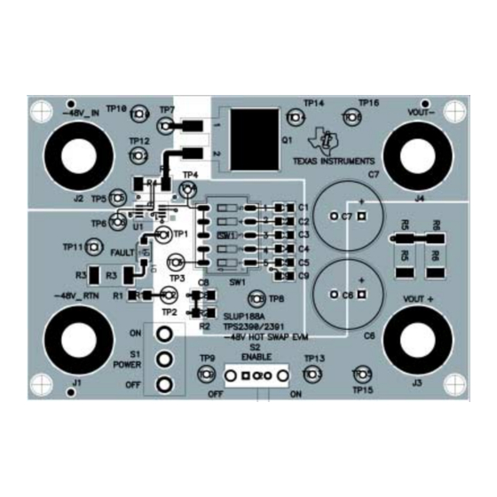
- Page 6 SLUU150 – February 2003 Figure 1. Evaluation Module Top Assembly EVM Schematic Diagram and List of Materials The EVM schematic diagram is shown in Figure 2. Evaluation Modules for Simple –48-V Hot Swap Controllers...
- Page 7 TP11 TP13 TP15 VOUT+ –48 V_RTN POWER 20 kΩ 20 kΩ 200 kΩ 12 kΩ 1/8 W, TPS2390DGK TPS2391DGK 100 µF 100 µF TP14 TP16 100 V 100 V FAULT VOUT– GATE SUB85N10 ENABLE FLTTME ISNS 7.32 kΩ 1/8 W, 1% USER IRAMP –VIN...
- Page 8 SLUU150 – February 2003 Table 1. List of Materials QUANTITY REFERENCE REFERENCE DESCRIPTION DESCRIPTION MANUF MANUF PART NUMBER PART NUMBER DESIGNATOR –002 –001 Texas – IC, Simple –48-V Hot Swap Controller, w/Retry TPS2391DGK Instruments Texas – IC, Simple –48-V Hot Swap Controller, Latching TPS2390DGK Instruments TP1–TP4, TP6,...
- Page 9 (2) Currents are positive into and negative out of the specified terminal. Getting Started Equipment Requirements The following test equipment is required to use the simple –48-V hot swap EVM (TPS2390EVM or TPS2391EVM). • Power supply, 80 V Vdc at 3-A minimum •...
- Page 10 J2 (–48V_IN) TP15 J1 (–48V_RTN) TP14 TP8/TP12 (GND) CH 1 CH 2 OSCILLOSCOPE CH 3 CH 4 TP16 Simple –48-V Hot Swap Controller Evaluation Module (TPS2390EVM/TPS2391EVM) UDG–03019 Figure 3. Evaluation Module Setup Evaluation Modules for Simple –48-V Hot Swap Controllers...
- Page 11 SLUU150 – February 2003 3.2.2 Functional Test 1. Turn on the power supply. On the EVM, place the POWER switch in the ON position. Verify the red LED is OFF. Verify the DVM reading is 0 ±100 mV. 2. Place the ENABLE switch in the ON position. Verify the red LED remains off, and the DVM now displays approximately the input supply voltage level.
- Page 12 SLUU150 – February 2003 Using the Evaluation Module to Evaluate the TPS2390/1 Procedures similar to the steps of Section 3.2.2 for functional test of the EVM can also be used to continue evaluation of the TPS2390 and TPS2391 hot swap controllers. Additional details about the EVM features are provided in this section.
- Page 13 SLUU150 – February 2003 Changing the Current Limit Threshold During power-up of a plug-in card, the TPS2390 and TPS2391 limit the peak inrush current drawn by the discharged bulk capacitance. The LCA senses load current as the drop across an external sense resistor.
- Page 14 SLUU150 – February 2003 To observe the controller response to a load that does not charge up as expected (a shorted or otherwise excessive load), set switches SW1–1, SW1–2, and SW1–3 to the ON position. This greatly reduces the inrush (load charging) current slew rate at turn-on, with a corresponding increase in the amount of time needed to successfully charge the intended load.
- Page 15 SLUU150 – February 2003 If the target application requires fault timing other than that provided by the default EVM setup, a new value of timing capacitor can be calculated from equation (3). When selecting from the readily available capacitor values for the result of equation (3), default to a slightly larger, rather than smaller, capacitor.
- Page 16 IMPORTANT NOTICE Texas Instruments Incorporated and its subsidiaries (TI) reserve the right to make corrections, modifications, enhancements, improvements, and other changes to its products and services at any time and to discontinue any product or service without notice. Customers should obtain the latest relevant information before placing orders and should verify that such information is current and complete.
Need help?
Do you have a question about the TPS2390EVM and is the answer not in the manual?
Questions and answers