Table of Contents
Advertisement
Quick Links
Advertisement
Table of Contents
Troubleshooting

Related Manuals for baxter Starling


Summary of Contents for baxter Starling
- Page 1 User Guide...
- Page 2 ©2020 Baxter International Inc. All rights reserved. Document Number: B-UG-01 Rev 3 - May 2021.
-
Page 3: Preface
The information provided in this guide is applicable to the Starling Monitor running software version 5.6, or later. This guide is designed to serve as an accompanying document to the Starling Monitor. It is not intended to take the place of Starling System Training, which must be completed by the operator before using the system. -
Page 4: Intended Use
Personnel should complete a training program prior to operating the Starling system. Do not use this system if you have not been adequately trained in its use by Baxter International Important Inc. personnel or by anyone authorized by Baxter International Inc. -
Page 5: Responsibility Of The Manufacturer
Responsibility of the Manufacturer The manufacturer considers itself responsible for the effects on safety, reliability, and performance of the equipment only if: Service and repair of the Starling Monitor are carried out by Baxter personnel, or anyone authorized by Baxter. -
Page 6: Conventions Used In This Guide
Cautions may also be used to highlight a procedure or step needing particular care or consideration, as shown in the example below. Do not apply Starling Sensors to skin that is not intact or that shows signs of infection, allergic CAUTION conditions, burns, etc. - Page 7 Important notes are used to identify procedures or steps that must be performed to ensure normal or optimal system performance. A typical example is shown below. For patients requiring monitoring for a period longer than 48 hours, Starling Sensors in current use Important must be replaced with a new set of Sensors.
-
Page 8: Terms And Abbreviations
Parameter that indicates the change in percentage terms from the average TFC acquired in TFCdO the first five TFC readings. Total Peripheral Resistance TPRI Total Peripheral Resistance Index Ventricular Ejection Time Electrical impedance of the chest cavity Note For detailed information, refer to Table B-2 on page B-2. Starling Monitor - User Guide... -
Page 9: Table Of Contents
Operational Use of the Starling Monitor ........ - Page 10 Guidelines for Safe Handling of the Starling Monitor ....... . .
- Page 11 Clinical Situations Potentially Affecting Starling Algorithm Accuracy or Performance . . . 2-4 Patient Populations in Which the Starling Monitor Has Not Been Tested ....2-5 Theory of Operation .
- Page 12 Starling IV Pole Mount Connector ........
- Page 13 Session Browser Window ............3-32 ©2020 Baxter International Inc.
- Page 14 Attaching the Starling IV Pole Mount Connector ........
- Page 15 Connecting the Sensors to the Starling Patient Cable ....... . .
- Page 16 Cleaning and Disinfecting the Starling Monitor........
- Page 17 Starling IV Pole Mount Connector ........
- Page 18 NIBP Cuff Selection and Placement ..........C-5 NIBP Cuff Sizes Available for Use with the Starling Monitor......C-7 NIBP Module Performance .
- Page 19 Connection of an External Patient Monitor ..........C-18 ©2020 Baxter International Inc.
- Page 21 Starling Monitor Mounted on Roll Stand ....... . . 2-25...
- Page 22 Patient Management Window......... . . 3-28 Starling Monitor - User Guide...
- Page 23 Figure 4-2 Starling Monitor Secured on the Roll Stand ....... 4-4 Figure 4-3 Starling IV Pole Mount Connector Attached to Monitor .
- Page 24 Message Displayed Prior to Starting PLR Test ......5-37 xxii Starling Monitor - User Guide...
- Page 25 Dynamic Assessment Tab - Latest Test Results ......5-54 Figure 5-51 Frank-Starling Curve - Interpretation of Stroke Volume Increase ... 5-55 Figure 5-52 Dynamic Assessment Test Results - Full Screen View .
- Page 26 NIBP Cuff Placement ........... C-6 xxiv Starling Monitor - User Guide...
- Page 27 Starling Monitor - Dimensions and Weight ........
- Page 28 Table B-11 Test Specifications for Enclosure Port Immunity to RF Wireless Communications B- Table C-1 NIBP Cuff Sizes Available for Use with the Starling Monitor ....C-7 Table C-2 NIBP Module Performance .
-
Page 29: Chapter 1 - Safety Information
Starling Monitor during the monitoring procedure. If using the Starling Monitor on an IV pole, check that the Starling IV Pole Mount Connector (optional accessory) is firmly secured to the rear of the Monitor and that the Connector is properly fastened onto the IV pole. -
Page 30: Prescription Notice
Equipment Classification In the European Union, the Starling system is classified as Class IIa, continuously operated, ordinary equipment with applied part and with signal input output parts. The device is not intended for use in the presence of flammable mixtures. -
Page 31: Electrical Safety
For an explanation of the battery status indicators displayed on the Monitor’s Control Panel, refer to Note Table 2-2 on page 2-16. The Starling Monitor is fitted with two fuses (2A), located in a fuse housing on the rear panel (shown in Figure 2-7 on page 2-12). -
Page 32: Grounding
Use ONLY the AC power cable supplied with the system and, to ensure proper grounding, connect to a receptacle marked HOSPITAL ONLY or HOSPITAL GRADE. It is not recommended to use an extension cord to connect the Starling Monitor to a mains power outlet. -
Page 33: Protection Against Ingress Of Liquids
Protection Against Ingress of Liquids Protection Against Ingress of Liquids The Starling Monitor is protected against the ingress of liquids in accordance with the IEC 60259 safety standard. The system is classified as having an ingress protection rating of IXP0. -
Page 34: System Safety Labels
The following provides explanations for the symbols and icons used, as well as details of the various label locations. Starling Monitor Safety Label The Starling system safety rating and manufacturer label, located on the Monitor side panel (see Figure 1-3), shows details of all applicable input and output specifications, certifications, manufacturer, etc. -
Page 35: Figure 1-2 Starling Monitor With Spo2 - Safety Rating And Manufacturer Label
System Safety Labels Figure 1-2 Starling Monitor with SpO2 - Safety Rating and Manufacturer Label Table 1-2 Starling System - Safety Rating and Manufacturer Label Symbol Description Catalog number Serial number Type BF applied part - complying with IEC 60601-1. - Page 36 System Safety Labels Table 1-2 Starling System - Safety Rating and Manufacturer Label (continued) Symbol Description Temperature range Max 50 C (122 F); Min 5 C (41 Relative humidity range Max 85%; Min 15% Atmospheric Pressure range Max 1060hPA; Min 700hPA Waste Electrical and Electronic Equipment (WEEE) Disposal.
- Page 37 System Safety Labels Table 1-2 Starling System - Safety Rating and Manufacturer Label (continued) Symbol Description Consult operating instructions. TUV mark of certification (Canada; US) CE mark of certification - indicates European conformity. Authorized Representative in the European Community - name and address.
-
Page 38: Location Of Safety Labels On System Components
System Safety Labels Location of Safety Labels on System Components Label on Monitor Side Panel Label Figure 1-3 Starling System Safety Label - Location on Side Panel 1-10 Starling Monitor - User Guide... -
Page 39: Safety Labels On Accessories And Disposables
Safety Labels on Accessories and Disposables Label on Pack of Disposable Starling Sensors Each set of Starling Sensors outer pack is marked with a safety label on the front and back. For an explanation of the symbols used, see Table 1-3. -
Page 40: Table 1-3 Disposable Starling Sensors - Symbol Descriptions
System Safety Labels Table 1-3 Disposable Starling Sensors - Symbol Descriptions Icon/Symbol Description Icon/Symbol Description Do not reuse. CE mark of certification. Latex free. Do not use if package is damaged. Store in a cool place and keep away from Caution: law prohibits dispensing sunlight. -
Page 41: System Software
Baxter International Inc. Do not attempt to install any additional software programs on the Starling Monitor. In the event that additional software is installed, proper operation of the Starling system cannot be Important guaranteed by the manufacturer. In addition, the warranty may be voided. -
Page 42: Guidelines For Safe Handling Of The Starling Monitor
Guidelines for Safe Handling of the Starling Monitor Guidelines for Safe Handling of the Starling Monitor WARNING When connecting the Starling Monitor to AC power, ensure the provided voltage is in the allowed range. Use only the AC power cable supplied with the system and, to ensure proper grounding, ... -
Page 43: Environmental Requirements
5°C — 50°C Operation, Storage, 15% — 85% 700 — 1060 and Transportation 41°F — 122°F The manufacturer’s recommendations for storage temperature of the Starling Sensors are shown in Table 1-5. Table 1-5 Recommended Temperature Conditions - Starling Sensors Ambient Condition Temperature 5°C—30°C... -
Page 44: Space And Positioning
Alternatively, make sure the Monitor is placed securely on a flat, stable surface that is free of dirt and debris. Always ensure the air inlet port on the Starling Monitor rear panel is open to freely circulating air and that the air inlets are not obstructed. -
Page 45: Patient Safety And Handling Guidelines
When the battery capacity is low, in the event that the Starling Monitor is not connected to the mains Important power, the system will automatically shut down safely. -
Page 46: Use Of Accessories And Disposables
Sensor re-calibration must be performed after placement of Starling Sensors, and must be repeated at least once per day. In the unlikely event that the patient has an allergic reaction to the Starling Sensors, detach the sensors immediately from the patient and avoid any further placement of Starling Sensors on this patient. - Page 47 Do not use a Starling Sensor if it was dropped prior to, or during, positioning. Do not apply a Starling Sensor to skin that is not intact or that shows signs of infection, allergic conditions, burns, etc.
-
Page 48: Data Handling
Data Handling Data Export The Starling system provides the option to export a patient’s measurement data acquired during Monitoring sessions to external media (disk-on-key), if required. The data is exported in Excel or PDF format, as selected by the user. -
Page 49: Data Storage
Data Handling Data Storage The Starling Monitor has a relatively large data storage capacity. While signals themselves are not saved, all measurements and patient demographic data are automatically saved to the system’s database. Eventually, once the system memory becomes full, by default, the oldest data will be deleted and the most-recently acquired data will be automatically saved. -
Page 51: Chapter 2 - Starling Monitoring System
Total Peripheral Resistance (TPRI) Dynamic Assessment Reports - highlight the change in SVI in response to a fluid challenge (PLR or Fluid Bolus), presented as an indicator on the Frank-Starling curve. Continuous monitoring of all hemodynamic variables. Additional module options (NIBP and SpO ... - Page 52 Starling Sensors. These are disposable accessories applied to the patient’s body and connected to the Starling Monitor via the customized Starling Patient Cable. Additionally, use of the Starling Monitor provides three methods by which a patient’s Blood Pressure (BP) readings can be acquired. These are as follows: Use of the optional NIBP Module.
-
Page 53: Indications For Use
Indications for Use Indications for Use The Starling with NIBP and SpO2 functionalities is a portable, hemodynamic monitoring non- invasive Cardiac Output monitoring device that monitors and displays a patient's Cardiac Output (CO) in Ltr/Min with a Non-Invasive Blood Pressure (NIBP) function that non-invasively measures and displays blood pressure (diastolic, systolic and mean arterial pressure) and heart rate and with a SpO2 function that non-invasively measures and displays blood oxygen saturation (SpO2). -
Page 54: Limitations Of Use
Indications for Use The Starling with NIBP and SpO2 functionalities is intended for use within hospitals and other healthcare facilities (e.g., outpatient clinics) that provide patient care. Limitations of Use Clinical Situations Potentially Affecting Starling Algorithm Accuracy or Performance Most of the clinical situations and patient conditions listed below may impact absolute values but... -
Page 55: Patient Populations In Which The Starling Monitor Has Not Been Tested
changes in aortic blood volume. With a continuous flow LVAD, by definition, there are little if any pulsations unless the heart itself ejects. Therefore, use of the Starling device in these patients is not recommended. Any serious incident that has occurred in relation to the device should be reported to Baxter International Important Inc. -
Page 56: Theory Of Operation
Theory of Operation In addition to utilizing advanced Bioreactance technology, the theory behind operation of the Starling system is the use of time delay or phase shifts which occur when an alternating electrical current is passed through the thorax. Method of operation is as follows: Four noninvasive sensor pads are applied to the thorax, creating a ‘box’... -
Page 57: Figure 2-1 Application Of Starling Sensors
Figure 2-1 Application of Starling Sensors As the heart expands and contracts, a time delay (phase shift) is created in the current by blood flow. The Starling Monitor then uses this Phase Shift as a baseline for measurement - illustrated in Figure 2-2. -
Page 58: Figure 2-2 Baseline Phase Shift
With a Fluid Bolus, if the heart can receive more fluid, greater outflow and a longer time delay will be observed - equivalent to the increase in Stroke Volume. Figure 2-3 Increase in Phase Shift Starling Monitor - User Guide... -
Page 59: Figure 2-4 Stroke Volume Increase >10% - Indicates Patient Is Fluid Responsive
If the Stroke Volume increase is >10%, the patient is determined to be fluid responsive . This is also represented on the Starling Monitor by the estimated location of the indicator on the Frank-Starling curve. This will be on the steep ascending portion - example shown in Figure 2-4. Indicator on Frank-Starling Curve Figure 2-4 Stroke Volume Increase >10% - Indicates Patient is Fluid Responsive... -
Page 60: System Configuration
In addition to the above, a range of optional accessories is available: Optional Accessories These items must be ordered separately and are not supplied as standard with the Starling Monitor. For details, see Accessories - Optional on page 2-23. -
Page 61: Figure 2-6 Starling Monitor - Front View (Operator Panel)
System Configuration Figure 2-6 Starling Monitor - Front View (Operator Panel) Legend, Figure 2-6 Touch Screen - LED Display Power On Button Back Button Main Menu Button Display Control Knob ©2020 Baxter International Inc. 2- 11... -
Page 62: Figure 2-7 Starling Monitor - Rear View
(e.g. Patient Monitor or EMR system). USB ports - enables user to connect a USB Thumb Drive (USB storage device) to Export acquired monitoring results stored in the Starling Monitor database. USB-2 port - for use by Service personnel only. -
Page 63: Figure 2-8 Starling Monitor - Side And Top Views
System Configuration Figure 2-8 Starling Monitor - Side and Top Views Legend, Figure 2-8 Starling Patient Cable connection socket NIBP air hose connection socket cable connection socket Carry handle USB port - enables the user to Export a patient’s monitoring session results to a USB storage device. -
Page 64: Operator Panel
Operator Panel Touch Screen - LED Display The Starling Monitor has a 10.4" LED display that enables full control and continuous real- time monitoring of the acquired patient data. The display may be used as a touch screen, whereby user interaction with the system is through simply touching or tapping the screen with one finger;... -
Page 65: Buttons
Press once to open the Quick Access menu; press x to close the menu. If Monitoring Session currently active : Press once to open the Main menu; press again to close. Back Button Used to close a sub-menu. ©2020 Baxter International Inc. 2- 15... -
Page 66: Internal Chargeable Batteries
Power Mode - see explanations in Battery Power Mode. Whenever power to the Starling Monitor is On, the charged status of the batteries is always indicated by the display of a Battery Status icon - shown in Table 2-2. It is recommended that users routinely observe the on-screen Battery status indicator for Note satisfactory operation of the recharging process. -
Page 67: Battery Power Mode
(without prompting the user). In the event of malfunction, or for replacement of the battery pack, it is necessary to contact a Baxter Service Center for assistance - refer to the details provided in Battery Replacement on page 6-12. -
Page 68: Accessories - Standard
System Configuration Accessories - Standard AC Power Cable The Starling Monitor is supplied with its own dedicated AC power cable for connection to the mains power. Use only this cable - see the Warnings shown in Grounding on page 1-4. -
Page 69: Nibp Module
The NIBP Module is supplied as a standard accessory, together with the Starling Monitor. The NIBP Module of the Starling device is an oscillometric blood pressure system. The module is designed to take blood pressure measurements on demand. After each blood pressure measurement, the Module will discard the previous blood pressure results. -
Page 70: User Guide Cd
Connecting the NIBP Air Hose to the Monitor on page 4-11. User Guide CD For quick and easy reference, the Starling Monitor User Guide (this document) is supplied on a CD, with the system. 2-20 Starling Monitor - User Guide... -
Page 71: Disposable Starling Sensors
To sample, at a very fast rate, the signal emanating from the patient - the Bioreactance signal. These signals are then analyzed by the Starling software algorithms, which determine the stroke volume (SV), heart rate (HR), cardiac output (CO) and other hemodynamic information acquired by the Starling Monitor. -
Page 72: Figure 2-11 Disposable Starling Sensors - Single Set Contents
Reuse of Starling Sensors may cause a risk of cross-contamination, or affect measurement accuracy and/or Starling system performance. Reuse of Starling Sensors can cause infection, allergic reaction and loss of hemodynamic parameters. For safety guidelines and manufacturer recommendations, see Disposable Starling Sensors on page 1-18. -
Page 73: Accessories - Optional
Accessories - Optional Module The SpO Module is an optional accessory that may be ordered for use with the Starling Monitor, if required. Pulse oximetry is a non-invasive method allowing the monitoring of the arterial oxygen saturation of a patient's hemoglobin. -
Page 74: Figure 2-12 Spo Cable
System Configuration Figure 2-12 SpO Cable For SpO Module specifications and additional details, see on page C-13. Note 2 Module (Optional) See also Connecting the SpO on page 4-12. 2 Cable to the Monitor 2-24 Starling Monitor - User Guide... -
Page 75: Roll Stand
System Configuration Roll Stand The Roll Stand is an optional accessory approved by Cheetah Medical for use with the Starling Monitor. To provide optimal, secure and convenient positioning of the Starling Monitor within the clinical environment, use of the Roll Stand is recommended. -
Page 76: Starling Iv Pole Mount Connector
System Configuration Starling IV Pole Mount Connector The Starling IV Pole Mount Connector is an optional accessory approved by Cheetah Medical for use with the Starling Monitor. This custom-shaped connector is specially designed to provide a convenient mounting option, enabling the Starling Monitor to be clamped securely onto an IV pole. -
Page 77: Starling Carry Bag
System Configuration Starling Carry Bag The strong and durable Starling Carry Bag provides a safe and convenient carrying option for easy portability of the Starling Monitor. Figure 2-15 Starling Carry Bag The Starling Monitor can be operated through the transparent front cover, as shown in Figure 2-15. -
Page 78: Lift
System Configuration Lift The Lift is an optional accessory, supplied by Baxter for use when performing a Passive Leg Raise (PLR) Dynamic Assessment Test. This provides a convenient method of raising the patient’s legs to the required angle (45 degrees) and supporting them comfortably during the second stage of the Test. -
Page 79: Operating Modes
The Starling system has five operating modes ( each described below. Startup Mode After turning on power to the Starling Monitor, the system boot-up process commences. (Refer System Startup Procedure on page 4-8). On completion, the Welcome Screen is displayed... -
Page 80: Pause Mode
Mode. The Monitoring session now resumes and active data acquisition continues. Pause While the Starling Monitor is operating in mode, a clear, visual indication of the currently-Paused status is shown on the display - for the duration of the paused segment, a... -
Page 81: Clinical Workflow
Clinical Workflow Clinical Workflow Figure 2-17 illustrates a typical clinical workflow when using the Starling Monitor. Positioning the Starling Monitor Patient Preparation Check Monitor is securely mounted (Roll Stand, IV pole or Table-top) Connecting the AC Power Cable Attaching Starling Sensors... -
Page 83: Chapter 3 - Starling Monitor Display
Introduction to the Touch Screen Display and Controls Main Screens and Controls The Starling Monitor display is designed for easy operation. Screens and controls are grouped and presented to facilitate the clinic workflow. For reference, they are described accordingly, as follows: Home Screen ... -
Page 84: Using The Display Control Knob
Messages and Pop-up Windows The system displays on-screen messages and Warnings, as and when applicable. Do not proceed beyond a displayed Warning message until the conditions are fully understood and the appropriate preventive action has been taken. Starling Monitor - User Guide... -
Page 85: Quick Access Menu
3-23. Opens Help menu - for list of topics, see Help Menu on page 3-10. Opens Main menu - see Figure 3-3. Used to perform System Shutdown. See System Shutdown Procedure on page 4-13. ©2020 Baxter International Inc. 3- 3... -
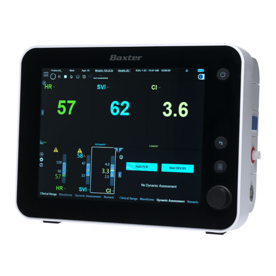
Page 86: Home Screen
Real-time Values - enlarged view of actual (real-time) one of four categories of data, in accordance with values for hemodynamic parameters currently selected the currently-selected tab (Clinical Range, for display - see Figure 3-12. Waveforms, Dynamic Assessment or Numeric). Starling Monitor - User Guide... -
Page 87: Main Menu
Home Screen Main Menu The Main menu provides access to a range of controls and settings, conveniently grouped into categories - see Table 3-1 for explanations. Figure 3-3 Main Menu ©2020 Baxter International Inc. 3- 5... - Page 88 External Art , or None Internal NIBP Automatic Mode (Off/On) Internal NIBP Time Interval (options between 1 min and 90 mins). Internal NIBP Initial Inflation (options between 120 mmHg and 200 mmHg). Starling Monitor - User Guide...
- Page 89 Opens the Patient Management Window. Used to: Search Patient List Add a New Patient Select a listed Session Start a New Session Delete a Patient Export Monitoring results (to USB storage device) ©2020 Baxter International Inc. 3- 7...
- Page 90 Set Language Internal NIBP - indicates whether or not NIBP Module is connected to the Starling Monitor. Internal SPO - indicates whether or not SPO Module is connected to the Starling Monitor. Touch Screen Calibration - used to perform ...
-
Page 91: Controls Toolbar
3-34. Note: if no Session History, button is disabled. Displays time (hrs and mins) since last Dynamic Assessment performed. If a Dynamic Assessment test is currently being performed, will show "In Progress". ©2020 Baxter International Inc. 3- 9... -
Page 92: Help Menu
Patient Information Management Sensor Placement Dynamic Assessment Clinical Range Display Trend Display Numeric Display Waveforms Display Real-Time Values Display Starling Tools Troubleshooting Guide 3-10 Starling Monitor - User Guide... -
Page 93: Trends Area
12 hours, the Session History button on the Controls Toolbar becomes enabled. When Viewing Trends in History Mode (see page 3-34) the horizontal scrollbar, together with the Display Control Knob, can be used to move easily through the Trends history. ©2020 Baxter International Inc. 3- 11... -
Page 94: Viewing The Trends Display
Home Screen Viewing the Trends Display For viewing the Trends display, the Starling Monitor provides the user with much flexibility via the various controls and options provided, as follows: Add or Remove a Trend Parameter, drag a Trend to a new position, or zoom the Trends ... -
Page 95: Figure 3-7 Sv Parameter Showing Sv Average Values
Figure 3-7. Figure 3-7 SV Parameter showing SV Average Values To hide the display of Average Values, tap on the graph, then deselect the Show Average option from the menu. ©2020 Baxter International Inc. 3- 13... -
Page 96: Controlling The Trends Display
Drag a Trend parameter to a New Position Tap-and-drag a listed parameter to the required position. The parameter moves to the new position in the list; the screen refreshes, showing the corresponding change in the Trends area. 3-14 Starling Monitor - User Guide... -
Page 97: Figure 3-8 Trends Area - Collapsed And Full-Width Views
Expand/Collapse Full-Width View right Tap icon on (see Figure 3-8) to expand Trends to full-width view. Tap again to collapse view. Tap for Full-Width View Figure 3-8 Trends Area - Collapsed and Full-Width Views ©2020 Baxter International Inc. 3- 15... -
Page 98: Figure 3-9 Trends Area - Collapsed And Full-Screen Views
Expand/Collapse Full-Screen View bottom right Tap icon at (see Figure 3-9) to switch Trends to full-screen view. Tap again to collapse view. Tap for Full-Screen View Figure 3-9 Trends Area - Collapsed and Full-Screen Views 3-16 Starling Monitor - User Guide... -
Page 99: Trends Area Markers
Home Screen Trends Area Markers The Starling system includes a feature whereby specific points of interest (in time), are marked as part of the monitoring measurement values history. Markers are added to the Trends display automatically whenever initiated manually by the user. -
Page 100: Adding An Event To The Trends Area
PLR Test Started PLR Test (Baseline stage) (Challenge stage) Figure 3-11 Markers - Enlarged View Adding an Event to the Trends Area Refer to the instructions for Adding an Event Manually on page 5-25. 3-18 Starling Monitor - User Guide... -
Page 101: Real-Time Values
Area may show a percentage value and an down arrow, indicating the following: Up arrow indicates a raised average SV/SVI (in comparison between the current average SV/SVI and former average SV/SVI); Down arrow indicates average SV/SVI is lowered. ©2020 Baxter International Inc. 3- 19... -
Page 102: Controlling The Real-Time Values Display
Expand/Collapse Full-Width View Tap icon on left (see Figure 3-13) to expand Values to full-width view. Tap again to collapse view. Tap for Full-Width View Figure 3-13 Parameter Values Area - Collapsed and Full-With Views 3-20 Starling Monitor - User Guide... -
Page 103: Figure 3-14 Parameter Values Area - Collapsed And Full-Screen Views
Expand/Collapse Full-Screen View Tap icon bottom left (see Figure 3-14) to expand Values to full-screen view. Tap again to collapse view. Tap for Full-Screen View Figure 3-14 Parameter Values Area - Collapsed and Full-Screen Views ©2020 Baxter International Inc. 3- 21... -
Page 104: Display Window
Minimum Set Clinical Range - opens dialog box to set limits. For instructions, see Setting or Adjusting Clinical Ranges on page 5-14. Opens Help providing Clinical Range guidance. Remove or Replace a displayed parameter. 3-22 Starling Monitor - User Guide... -
Page 105: Waveforms
- Average morphology of the Bioreactance signal dBioreactance - Average morphology derivative of the Bioreactance signal Figure 3-17 Display Window - Waveforms Tab Use the full-width or full-screen viewing options ( previously described ), as required. Note ©2020 Baxter International Inc. 3- 23... -
Page 106: Dynamic Assessment
Test results. To view previous results, see Dynamic Assessment Test Results in Full Screen View on page 5-56. See also Viewing Dynamic Assessment Test Results in History Mode on page 3-36. 3-24 Starling Monitor - User Guide... -
Page 107: Numeric
- refer to Figure 3-5. Viewing and scrolling options include the following: Use the horizontal scroll bar, or simply finger-swipe left right , as required. Switch to full-width or full-screen view (as previously described). ©2020 Baxter International Inc. 3- 25... -
Page 108: Adding An Event To The Numeric Display
In the Numeric display, the user has the option to add an Event, if required. Note When Every Event is the selected Time Frame, only Event times are shown in the Display window Numeric tab. Refer to the instructions for Adding an Event Manually on page 5-25. 3-26 Starling Monitor - User Guide... -
Page 109: Changing The Home Screen Display Layout
Whenever system shutdown has been performed, at the next system startup, the Home screen will automatically be displayed with this view. Should the user require any modifications to the available templates, or to change the Default template option, contact Baxter Technical Support for assistance: email: starling_rma@baxter.com Tel (worldwide): +1 360-828-8685 ©2020 Baxter International Inc. -
Page 110: Patient Management Window
From the Main menu, select the Browse Existing Sessions option. Figure 3-23 Patient Management Window The Patient Management Window opens, displaying a list of all patients currently in the Starling database, showing ID number Last Session (date and time) and Session Duration for each. -
Page 111: Function Buttons
Refer to Starting a Monitoring Session on page 5-10. Opens the Session Browser Window (Figure 3-26), enabling the user to browse the currently-selected Monitoring Session. Refer to Browsing Monitoring Session History on page 5-58. ©2020 Baxter International Inc. 3- 29... -
Page 112: Selected Patient File
Dynamic Assessments Sessions are listed chronologically, with the most-recent at the top of list. Note When many Sessions are listed, a vertical scroll bar is available on the right of the screen. 3-30 Starling Monitor - User Guide... -
Page 113: Deleting A Patient File
Patient Management Window Deleting a Patient File The Starling Monitor provides the user with the option to delete a Patient File, if required. The delete process is irreversible! Important Always make sure the CORRECT Patient is currently selected before proceeding. -
Page 114: Session Browser Window
Trends area and Trends display controls - refer to Trends Area on page 3-11. Numeric display - see explanations in Numeric on page 3-25. Dynamic Assessment display - see Dynamic Assessment on page 3-24. 3-32 Starling Monitor - User Guide... - Page 115 When browsing a Monitoring Session, the user has the option to Export that specific Session’s monitored data, if required. See the instructions for Data Export on page 5-62. For more details, see Browsing Monitoring Session History on page 5-58. ©2020 Baxter International Inc. 3- 33...
-
Page 116: Using History Mode
Swipe the display left or right to move through the Trends history Using the Display Control knob, place the focus on the horizontal scroll bar, press the knob, then turn left or right, as required. 3-34 Starling Monitor - User Guide... -
Page 117: Figure 3-27 Trends Area - Full Screen View Showing Sessions Indicator
Figure 3-27 Trends Area - Full Screen View showing Sessions Indicator Legend, Figure 3-27 Previous Monitoring Session Pause between Sessions (i.e. period of no active monitoring) Current Monitoring Session Session # (in this example, #1) Horizontal scrollbar Session indicator ©2020 Baxter International Inc. 3- 35... -
Page 118: Viewing Dynamic Assessment Test Results In History Mode
The display switches to History Mode; a Session indicator is now displayed at the bottom of the screen (below the page indicator), as shown in Figure 3-28. Page indicator Session indicator Figure 3-28 Viewing Multiple Dynamic Assessment Test Results in History Mode 3-36 Starling Monitor - User Guide... - Page 119 For a detailed explanation of the information presented in the displayed Dynamic Assessment Test Note Results, refer to Explanation of Dynamic Assessment Test Results on page 5-54 ©2020 Baxter International Inc. 3- 37...
-
Page 120: Viewing Numeric Data In History Mode
In the Session indicator, Monitoring Sessions are numbered sequentially (1,2,3 etc.) from right to Note left (i.e. backwards chronologically). In addition, a vertical blue line is displayed on one Session, indicating that is the Session for which Results are currently being viewed. 3-38 Starling Monitor - User Guide... - Page 121 Swipe the display left or right to move through the Numeric data history Using the Display Control knob, place the focus on the horizontal scroll bar, press the knob, then turn left or right, as required. ©2020 Baxter International Inc. 3- 39...
-
Page 123: Chapter 4 - System Preparation, Startup And Shutdown
IV pole), connecting cables, turning ON power, The system preparation procedures may be performed by personnel who have received system training from Baxter, and should be carried out in the order in which they are described. First-time Use Unpacking of the Starling Monitor as well as all calibration and initial setup procedures are performed by the user. -
Page 124: Positioning The Starling Monitor
Positioning the Starling Monitor WARNING To prevent possible damage to the Starling Monitor, always secure it to the Roll Stand or IV Pole. Alternatively, place securely on a flat, stable surface that is free of dirt and debris. When positioning the Starling Monitor, observe the following precautions: CAUTION Do not place the Monitor near a radiator or heating unit. -
Page 125: Mounting The Monitor On The Roll Stand
Positioning the Starling Monitor Mounting the Monitor on the Roll Stand To provide optimal, secure and convenient positioning of the Starling Monitor within the clinical environment, use of the optional Roll Stand is recommended. To Mount the Monitor on the Roll Stand 1. -
Page 126: Figure 4-2 Starling Monitor Secured On The Roll Stand
Positioning the Starling Monitor Figure 4-2 Starling Monitor Secured on the Roll Stand 6. Release the locking brakes and move the Roll Stand into the required position in proximity to the patient. Make sure it is standing on a level surface, then lock the brakes again to prevent movement. -
Page 127: Attaching The Starling Iv Pole Mount Connector
2. If currently connected, disconnect the Starling Patient Cable, NIBP air hose and SPO cable. 3. Using the 4 screws provided, attach the Starling IV Pole Mount Connector to the Monitor rear panel, as shown in Figure 4-3. -
Page 128: Mounting The Monitor On A Table Top
1. Carefully place the Monitor in the required position on a stable surface (for example, a bedside table.) 2. Check to ensure the Monitor is correctly positioned in accordance with the Recommended Guidelines for Monitor Positioning. Starling Monitor - User Guide... -
Page 129: Connecting The Ac Power Cable
Figure 4-4 Connecting the AC Power Cable to the Monitor 2. Plug the other end of the AC power cable into the mains power wall outlet. 3. Proceed to the instructions for Turning ON Power to the Monitor. ©2020 Baxter International Inc. 4- 7... -
Page 130: System Startup Procedure
Startup Screen is now displayed: Power button indicating Power ON Figure 4-5 System Startup Screen The system performs automatic self-testing; on completion of the Start-up process (approx 2 min), the Quick Access Menu is displayed - Figure 4-6. Starling Monitor - User Guide... - Page 131 For details, see Figure 3-1 on page 3-3. 3. If necessary, proceed to the instructions for Adding a New Patient on page 5-2. 4. Continue to the next procedure, Connecting the Starling Patient Cable. ©2020 Baxter International Inc. 4- 9...
-
Page 132: Connecting The Starling Patient Cable
2. Carefully push the connector into the socket, then turn it clockwise until it is fully locked. Figure 4-7 Connecting the Starling Patient Cable 3. Proceed to Chapter 5 – Patient Monitoring for instructions on patient preparation, attaching Starling Sensors and monitoring procedures. -
Page 133: Connecting The Nibp Air Hose To The Monitor
1. Holding the air hose in one hand, orient the connector notch with the flat part of the connection socket (Figure 4-8). clockwise 2. Carefully push the connector into the socket, then turn until locked. Notch Socket Figure 4-8 Connecting the NIBP Air Hose ©2020 Baxter International Inc. 4- 11... -
Page 134: Connecting The Spo Cable To The Monitor
1. Holding the cable in one hand, position it for correct orientation of the pins (Figure 4-9). 2. Carefully push the connector into the socket, until fully inserted. Connector on Monitor Multi-pin connector Figure 4-9 Connecting the SpO Cable 4-12 Starling Monitor - User Guide... -
Page 135: System Shutdown Procedure
Important Do not use the Power button on the Operator Panel. Turning OFF Power to the Starling Monitor To Turn OFF Power to the Monitor 1. Verify that no active Monitoring Session is in progress and that use of the Monitor is no longer required. -
Page 136: Disconnecting Cables
Storage When Not in Use In the event that the Starling Monitor will not be used for a prolonged period, it should be stored in a clean, dry environment in an area where it will be protected from the risk of damage. - Page 137 Chapter 5 – Patient Monitoring Introduction This chapter details the procedures typically required for Patient Monitoring sessions, using the Starling Monitor. The instructions and guidelines provided include the following: Creating a New Patient File on page 5-2 Patient Preparation on page 5-5 ...
- Page 138 Adding a New Patient To Add a New Patient 1. Access the Patient Management Window, shown below. Figure 5-1 Add a New Patient 2. Click the Add New Patient button. The screen refreshes - Figure 5-2. Starling Monitor - User Guide...
-
Page 139: Figure 5-2 Enter New Patient Details
1 and 90 ins (or between 2 and 229 cms). c. Tap the Weight field, then enter the weight (in accordance with displayed measurement units). Note: Value must be between 0.2 and 3307.5 lb (or between 0.09 and 1500 Kg). ©2020 Baxter International Inc. 5- 3... - Page 140 5-5, in readiness for Starting a Monitoring Session. In the event that power to the Starling Monitor is turned OFF before Starting a Monitoring Session Important the New Patient, the newly-added Patient details will not be saved. Later, this will necessitate repeating the above procedure in order to re-enter the New Patient details.
- Page 141 If alcohol is used to prep the skin, allow time for the skin to dry prior to placement of the Starling Sensors in order to preserve optimal gel performance. Do not apply Starling Sensors to skin that is not intact or that shows signs of infection, allergic CAUTION conditions, burns, etc.
- Page 142 Table 3-1 on page 3-6). Then repeat, once per day. In the unlikely event that the patient has an allergic reaction to the Starling Sensors, detach the sensors immediately from the patient and avoid any further placement of Starling Sensors on this patient.
-
Page 143: Figure 5-4 Four Areas For Positioning Of Starling Sensors
Note Figure 5-4 Four Areas for Positioning of Starling Sensors 6. Observe the orientation mark on each of the four Starling Sensor pairs (shown in Figure 5-5) and carefully proceed as follows: a. -
Page 144: Figure 5-5 Correct Orientation Of Sensors
Patient Preparation Orientation mark Orientation mark (outer - top) (outer -top) Orientation mark Orientation mark (outer -bottom) (outer -bottom) Figure 5-5 CORRECT Orientation of Sensors Figure 5-6 INCORRECT Orientation of Sensors Starling Monitor - User Guide... - Page 145 Starling notify the user that there is loss of signal or poor signal quality. Since Starling Sensors are designed for single use only, in the event that they become detached or are Important removed from the patient’s body for any reason, they should be replaced with a new set before continuing with the Monitoring Session.
-
Page 146: Figure 5-7 Sensor Placement Window - Calibration In Progress
Starting a Monitoring Session To Start a Monitoring Session 1. Check the Starling Sensors are correctly attached to the patient. 2. Instruct the patient to keep still for the next ~1 minute. 3. From the Patient Management window, make sure the correct patient is currently selected, then tap the Start New Session button. -
Page 147: Figure 5-8 Sensor Placement - Error Display
If the event of incorrect Sensor placement, the screen display prompts the user to check the Note appropriate lead (right, left, or both) - see Figure 5-8. Figure 5-8 Sensor Placement - Error Display ©2020 Baxter International Inc. 5- 11... -
Page 148: Figure 5-9 Home Screen - Monitoring Session Initial Display
Figure 5-10. 6. Proceed to view the monitored data - see Viewing an Active Monitoring Session. The system is now ready for Performing a Dynamic Assessment Test, as required. 5-12 Starling Monitor - User Guide... -
Page 149: Figure 5-10 Monitoring Session In Progress
Make any changes required (select parameter values for display, change to preferred display layout, .). Additionally, refer to the following, as applicable: Setting or Adjusting Clinical Ranges Pausing a Monitoring Session Setting Alerts Performing a Dynamic Assessment Test ©2020 Baxter International Inc. 5- 13... -
Page 150: Figure 5-11 Clinical Ranges Dialog Box
Monitoring a Patient Setting or Adjusting Clinical Ranges The Starling Monitor default Clinical Range settings are the generally-accepted normal ranges. For each displayed parameter value, the clinician is able to set or adjust the Clinical Range of Maximum and Minimum normal values ( limits), as required. -
Page 151: Choosing A Bp Source
2. From the BP drop-down menu, tap Internal NIBP Time Interval, then select the required time interval from the displayed list of options - see Figure 5-13. Internal NIBP measurements will now be acquired automatically in accordance with the time interval set. ©2020 Baxter International Inc. 5- 15... -
Page 152: Figure 5-13 Setting Internal Nibp Time Interval
In the Real-time Values area, an icon will be displayed indicating the time until the next Note Internal NIBP measurement (in accordance with the currently-selected NIBP Time Interval): Figure 5-14 Time Indicator for Next Internal NIBP Measurement 5-16 Starling Monitor - User Guide... -
Page 153: Using The Start Once Feature
1. Make sure Internal NIBP is selected as the BP Source. 2. Check the NIBP Cuff is positioned correctly on the patient’s arm and connected correctly to the Starling Monitor. Session Controls & Settings 3. Access the Main menu, then from... -
Page 154: Using The End Nibp Feature
From the BP parameter drop-down menu, select End NIBP - see Figure 5-16. Figure 5-16 Ending NIBP Measurement If in progress, NIBP measurement stops immediately. After this Session, the next new Monitoring Session will commence in Automatic NIBP measurement mode (if previously set). 5-18 Starling Monitor - User Guide... -
Page 155: Entering A Mean Arterial Pressure Measurement
2. Enter the acquired the MAP measurement, then tap OK to close the dialog box. The MAP measurement is now seen in the BP parameter display. The displayed value is labeled (User), indicating it was entered by the user. ©2020 Baxter International Inc. 5- 19... -
Page 156: Choosing An Spo 2 Source
Figure 5-19 SPO Results Displayed Note I results will be received if the Hgb measurement was entered before the SPO measurement. 5-20 Starling Monitor - User Guide... -
Page 157: Entering An Spo 2 Measurement
The displayed value is labeled (User), indicating it was entered by the user. I results will be received if the Hgb measurement was entered before the SPO measurement. Note ©2020 Baxter International Inc. 5- 21... -
Page 158: Entering An Hgb Measurement
Enter Hgb From the SPO , Hgb, or DO I parameter, open the drop-down menu, then tap Enter Hgb The Enter Hgb dialog box opens - Figure 5-21. Figure 5-21 Enter Hgb Dialog Box 5-22 Starling Monitor - User Guide... -
Page 159: Setting The Hgb Posting Period
A list of available Hgb Posting Period options opens - Figure 5-22. Figure 5-22 Hgb Posting Period - Available Options 2. Select the required Posting Period option. The Hgb measurement will now be displayed in accordance with the selected Posting Period. ©2020 Baxter International Inc. 5- 23... - Page 160 Active Monitoring is currently paused; a vertical Marker is displayed in the Trends area (refer to Figure 3-10 on page 3-17). 2. When ready, tap the Resume button to resume monitoring. The same Monitoring Session continues. 5-24 Starling Monitor - User Guide...
-
Page 161: Adding An Event Manually
In addition to Automatic Events (automatically added to the Trends area as previously described in Chapter 3) the Starling system provides the user with the option to add Events manually, as required. Each Manual Event is displayed as a green vertical line on the Trends area (see the example in Figure 3-10 on page 3-17). - Page 162 Tap the Dosage button, then use the virtual keyboard to enter the dose administered, then tap OK. Figure 5-24 Enter Dosage c. Set the appropriate Time of dose administration - tap the Time Change button to access the Set Time dialog box, Figure 5-25. 5-26 Starling Monitor - User Guide...
- Page 163 Tap OK to close the Events dialog box. The newly-added Event is now indicated by a green marker in the Trends area (and in the Numeric display, if the Event parameter has been selected for display in the table of values). ©2020 Baxter International Inc. 5- 27...
-
Page 164: Figure 5-26 Events Dialog Box - Events Tab
Tap OK to close the Events dialog box. The newly-added Event is now indicated by a green marker in the Trends area (and in the Numeric display, if the Event parameter has been selected for display in the table of values). 5-28 Starling Monitor - User Guide... -
Page 165: Figure 5-27 Events Dialog Box - Fluids Tab
Tap OK to close the Events dialog box. The newly-added Event is now indicated by a green marker in the Trends area (and in the Numeric display, if the Event parameter has been selected for display in the table of values). ©2020 Baxter International Inc. 5- 29... -
Page 166: Figure 5-28 Events Dialog Box - Other Tab
Tap OK to close the Events dialog box. The newly-added Event is now indicated by a green marker in the Trends area (and in the Numeric display, if the Event parameter has been selected for display in the table of values). 5-30 Starling Monitor - User Guide... -
Page 167: Table 5-1 Predefined Events - Available Options Listed Per Category
Dobutamine on Dobutamine given Dobutamine increased Dobutamine decreased Dobutamine off Intrope on Intrope given Intrope increased Intrope decreased Intrope off Primacore on Primacore given Primacore increased Primacore decreased Primacore off Dopamine on Dopamine given ©2020 Baxter International Inc. 5- 31... - Page 168 Vasopressor decreased Vasopressor off Nitroprusside on Nitroprusside given Nitroprusside increased Nitroprusside decreased Nitroprusside off Vasodilator on Vasodilator given Vasodilator increased Vasodilator decreased Vasodilator off Nitroglycerine on Nitroglycerine given Nitroglycerine increased Nitroglycerine decreased Nitroglycerine off 5-32 Starling Monitor - User Guide...
- Page 169 Patient Supine Patient in Trendelenburg Insufflation Gas removed Dialysis started Dialysis ended NS blood loss Fluids 250cc Fluid Bolus given 500cc Fluid Bolus given Fluids running Other Enter free text (use virtual keyboard), as required. ©2020 Baxter International Inc. 5- 33...
-
Page 170: Setting Alerts
The Starling Monitor provides the user with the option to turn the Audible Alert function On or Off, as required. When the Audible Alert option is set to On, in the event that, for example, one of the Starling Sensor leads becomes disconnected, the system will emit an audible beep to alert the user of the situation. -
Page 171: Responding To An Alert
The icon in the Controls toolbar returns to the Alert On status. In the event that after the 2-minute countdown the cause of the Alert has not been rectified, the Note Audible Alert will sound again. ©2020 Baxter International Inc. 5- 35... -
Page 172: Passive Leg Raise (Plr) Test
Performing a Dynamic Assessment Test In order to measure the patient’s ability to respond to fluid by directly challenging the heart with volume, the advanced Starling system protocols provide the user with two methods of performing a Dynamic Assessment test:... -
Page 173: Figure 5-32 Message Displayed Prior To Starting Plr Test
Otherwise, tap No and continue to Step 3. below. 3. Ensure there are no pillows or Lift under the patient’s legs and that (if in use) any Sequential Compression Device has been removed. 4. Tap Next. ©2020 Baxter International Inc. 5- 37... - Page 174 During this time, the system will obtain a Baseline for measurement. While the Baseline measurement is in progress, the Dynamic display shows a graph being drawn slowly from left to right, as well as a 3-minute countdown (min/secs). See the example in Figure 5-34. 5-38 Starling Monitor - User Guide...
-
Page 175: Figure 5-34 Plr Test - Baseline Measurement In Progress
Performing a Dynamic Assessment Test Test In Progress Baseline Countdown Baseline Graph Figure 5-34 PLR Test - Baseline Measurement in Progress ©2020 Baxter International Inc. 5- 39... - Page 176 To support the patient’s legs comfortably, use of the Lift (optional accessory) is recommended. Note Figure 2-16 on page 2-28. 7. Tap Next. The Challenge commences. 8. Keep the patient still in this position for 3 mins. 5-40 Starling Monitor - User Guide...
-
Page 177: Figure 5-36 Plr Test - Challenge In Progress
Figure 5-36 PLR Test - Challenge in Progress 9. As soon as the countdown reaches zero, the Challenge is complete. The system sounds a single beep. A message confirms successful completion of the Test - see Figure 5-37. ©2020 Baxter International Inc. 5- 41... -
Page 178: Figure 5-37 Plr Test Completed Successfully
The Dynamic Assessment window now provides a quick indication of the patient’s fluid responsiveness. 11. For an enlarged view of the displayed PLR Test Results, switch the Display window to full-screen view - Figure 5-38. 5-42 Starling Monitor - User Guide... -
Page 179: Figure 5-38 Viewing Plr Test Results - Enlarged View
5-38), showing a message and graphic representation of the patient’s fluid responsiveness as determined by the Starling system. In the above example, the indicator on the Frank-Starling curve and corresponding message are Note colored red (patient not fluid responsive). However, if the Test Results indicated the patient was fluid responsive, these would be colored green. -
Page 180: Figure 5-39 Viewing Plr Test Results - Enlarged View Page 2 (Showing Elapsed Time)
The elapsed time since the last Dynamic Assessment Test will continue to be updated in real time. Note right 12. To view the detailed Test Results (Page 1), swipe to the The display scrolls left; an example is shown in Figure 5-40. 5-44 Starling Monitor - User Guide... -
Page 181: Figure 5-40 Viewing Plr Test Results - Enlarged View
For a detailed explanation of the information presented in the displayed Dynamic Assessment Test Note Results, refer to Explanation of Dynamic Assessment Test Results on page 5-54. See also Dynamic Assessment Test Results in Full Screen View on page 5-56. ©2020 Baxter International Inc. 5- 45... -
Page 182: Figure 5-41 Display Window - Dynamic Assessment Tab
1. From the Home screen Display window, tap the tab. Figure 5-41 Display Window - Dynamic Assessment Tab 2. Tap the Start Bolus button. The Obtain Baseline message opens - Figure 5-42. Figure 5-42 Message Displayed Prior to Starting Bolus Test 5-46 Starling Monitor - User Guide... - Page 183 During this time, the system will obtain a Baseline for measurement. While the Baseline measurement is in progress, the Dynamic display shows a graph being drawn slowly from left to right, as well as a 3-minute countdown (min/secs). See the example in Figure 5-43. ©2020 Baxter International Inc. 5- 47...
-
Page 184: Figure 5-43 Bolus Test - Baseline Measurement In Progress
In the event that the Baseline results are considered by the system to be unstable, a warning Note message is displayed. The user has the option of nevertheless continuing to the Challenge stage, or restarting the Test again from the Baseline stage. Figure 5-44 Bolus Test - Measure SVI Change 5-48 Starling Monitor - User Guide... -
Page 185: Figure 5-45 Bolus Test - Challenge In Progress
Crit Care Med 2016; 44:880–891 1. Aya HD . Pharmacodynamic analysis of a fluid challenge. et al Curr Opin Crit Care 20 11:17:290-295 2. Cecconi M . What is a fluid challenge? ©2020 Baxter International Inc. 5- 49... -
Page 186: Figure 5-46 Bolus Test Completed Successfully
Bolus Challenge is 30 minutes. Keep the patient at rest, while no fluids are given. After 30 mins, the system sounds a single beep and the test ends automatically; the Results will be saved. 5-50 Starling Monitor - User Guide... -
Page 187: Figure 5-47 Viewing Bolus Test Results - Enlarged View
Starling system. Note In the above example, the indicator on the Frank-Starling curve and corresponding message are colored green (patient fluid responsive). However, if the Test Results indicated the patient was not fluid responsive, these would be colored red. -
Page 188: Figure 5-48 Viewing Bolus Test Results - Enlarged View Page 2 (Showing Elapsed Time)
The elapsed time since the last Dynamic Assessment Test will continue to be updated in real time. Note right. 8. To view the detailed Test Results (Page 1), swipe to the The display scrolls left; an example is shown in Figure 5-49. 5-52 Starling Monitor - User Guide... -
Page 189: Explanation Of Dynamic Assessment Test Results
For a detailed explanation of the information presented in the displayed Dynamic Assessment Test Results, refer to the following Explanation of Dynamic Assessment Test Results. See also Dynamic Assessment Test Results in Full Screen View on page 5-56. ©2020 Baxter International Inc. 5- 53... -
Page 190: Test Results In Dynamic Assessment Window
Message indicating patient’s fluid responsiveness as determined by the Starling system. a. If the SVI is >10%, the indicator is located on the ascending part of the Starling Curve. If the SVI is <10%, the indicator is located on the static part of the Starling Curve. -
Page 191: Figure 5-51 Frank-Starling Curve - Interpretation Of Stroke Volume Increase
Patient Considered to be FLUID RESPONSIVE Patient Considered to be NOT FLUID RESPONSIVE Figure 5-51 Frank-Starling Curve - Interpretation of Stroke Volume Increase The displayed indicator color (red or green) remains for a period of 15 minutes after completion of the Dynamic Assessment Test. Thereafter, the color changes to cyan and a new message... -
Page 192: Dynamic Assessment Test Results In Full Screen View
Displays the continuous results of the SVI during the PLR/Bolus Test; this is divided into the Baseline portion, and the Challenge portion. maximum The tip of the arrow is pointing to the point of the Challenge. : Starling Curve -see explanations in Figure 5-50 on page 5-54; : message indicating fluid responsiveness. - Page 193 In the event that there are more than four Dynamic Assessment Tests in the Session, use of the Note Display Control Knob will be necessary to access those not currently visible. By default, the column positioned on the most-right is that of the last Test performed in the Session. ©2020 Baxter International Inc. 5- 57...
-
Page 194: Browsing Monitoring Session History
1. Access the Main menu, then choose Browse Existing Sessions From the Controls toolbar, tap the Patient Management button. The Patient Management window opens: Figure 5-53 Patient Management Window 2. Scroll to the required Patient File, then tap Select. 5-58 Starling Monitor - User Guide... -
Page 195: Figure 5-54 List Of Monitoring Sessions For Selected Patient
Figure 5-54 List of Monitoring Sessions for Selected Patient 3. Scroll to the required Session, then tap Browse. The window closes and the selected Session is now displayed in the Session Browser Window - Figure 5-55. ©2020 Baxter International Inc. 5- 59... -
Page 196: Figure 5-55 Selected Monitoring Session Displayed In Session Browser Window
If the currently-selected Patient has had more than one Dynamic Assessment Test performed, to Note browse the Test Results refer to Dynamic Assessment Test Results in Full Screen View page 5-56. See also Viewing Dynamic Assessment Test Results in History Mode on page 3-36. 5-60 Starling Monitor - User Guide... -
Page 197: Saving A Screen Capture
Note To Save a Screen Capture 1. Ensure the information to be saved is displayed as required. 2. Insert a USB storage device into the USB port on the side of the Starling Monitor - refer to Figure 2-8 on page 2-13. -
Page 198: Data Export
Data Export Data Export Using the Starling data export function, the clinician has the option to export monitored data from all Monitoring Sessions performed on a currently-selected patient. This is performed from the Patient Management Window, as described below. Additionally, when using the Session Browser Window, data acquired from a single Monitoring... - Page 199 Data Export 3. Insert a USB storage device (flash drive/disk-on-key) into the USB port on the side of the Starling Monitor - refer to Figure 2-8 on page 2-13. 4. Tap the Export button. The Export Data dialog box opens.
- Page 200 Figure 5-59 Export Successful 7. Remove the flash drive from the USB port, then tap the Close button. The dialog box closes. Note The Exported Monitoring Session data can be viewed on any PC, as required. 5-64 Starling Monitor - User Guide...
-
Page 201: Exporting A Single Monitoring Session
To Perform the Data Export Procedure 1. Browse to select the required Monitoring Session to be exported. 2. Insert a USB storage device (flash drive/disk-on-key) into the USB port on the side of the Starling Monitor - refer to Figure 2-8 on page 2-13. - Page 202 PDF Full Report includes Test Graphs, Session Results, Dynamic Assessment Test Starling Results, Events, and Print Screens (as applicable). 7. Tap the Export button. The Export process commences; a progress bar is displayed - Figure 5-61. Figure 5-61 Export in Progress 5-66 Starling Monitor - User Guide...
- Page 203 8. Remove the flash drive from the USB port, then tap the Close button. The dialog box closes. The Exported Monitoring Session data can be viewed on any PC, as required. Note 9. Resume Monitoring Session browsing, as required. ©2020 Baxter International Inc. 5- 67...
-
Page 204: Completion Of Patient Monitoring
A message is displayed, prompting the user to confirm the command: Figure 5-63 Stop Session Message 3. Tap Yes to confirm. The message closes; the current Monitoring Session is now stopped. 4. Proceed to the instructions for Removing the Starling Sensors. 5-68 Starling Monitor - User Guide... -
Page 205: Removing The Starling Sensors
3. Carefully peel each of the Starling Sensors from the patient’s skin. 4. Dispose of the Starling Sensors. CAUTION Dispose of used Starling Sensors in accordance with hospital protocol and local safety regulations. Exporting Report Data If required, perform the Data Export procedure - for instructions, see... -
Page 207: Chapter 6 - Care And Maintenance
Chapter 6 – Care and Maintenance General Care and Maintenance Guidelines Cleaning and disinfecting the Starling Monitor and reusable accessories is recommended after use and always between patients. Refer to the following procedure instructions, as applicable: Cleaning and Disinfecting the Starling Monitor ... - Page 208 Starling Patient Cable), by cleaning with 70% medical-grade alcohol using a dampened soft towel or wipe. Refer to the precautions and procedure instructions below. Do not expose the Starling Monitor, Starling Patient Cable or Starling Sensors to sprays, liquids or CAUTION any other type of solvent.
- Page 209 Cleaning Procedures To avoid damage to the surface of the Starling Monitor: CAUTION Take care not to scratch the front display while cleaning. Avoid excessive pressure when cleaning lettering and printed labeling on the Monitor front, side and rear panels, as well as the adhesive label on the side panel.
- Page 210 Cleaning Procedures Cleaning the LED Display It is recommended to clean the Starling Monitor LED Display regularly, as described in the following procedure. This will help to maintain the LED Display in good condition and ensure optimal visual clarity during system use.
-
Page 211: Cleaning The Roll Stand
Storage When Not in Use In the event that the Starling Monitor will not be used for a prolonged period, it should be stored in a clean, dry environment in an area where it will be protected from the risk of damage. -
Page 212: Touch Screen Calibration
Touch Screen Calibration Touch Screen Calibration From time to time, calibration of the Starling Monitor Touch Screen may be required to optimize the screen responsiveness. Note If active Monitoring is currently in progress, it is not necessary to stop the Session before performing this procedure. - Page 213 On successful completion of Step 1, the Calibration Wizard Step 2 opens: Figure 6-3 Calibration Wizard - Start Step 2 3. Tap the Start Step 2 button. The Calibration screen opens - shown in Figure 6-4. ©2020 Baxter International Inc. 6- 7...
- Page 214 Pressing the Operator Panel Back Button at this stage will cancel the Calibration procedure. Note Once Step 2 is completed, the following message is displayed at the top of the Calibration screen: Starling Monitor - User Guide...
- Page 215 5. Press the Operator Panel Display Control Knob to accept the new calibration settings. A message confirming successful calibration opens - Figure 6-5. Figure 6-5 Touch Screen Calibration Successful 6. Tap OK to close the message. ©2020 Baxter International Inc. 6- 9...
-
Page 216: Fuse Replacement Procedure
Fuse Replacement Procedure Fuse Replacement Procedure The Starling Monitor is equipped with two mains AC fuses to protect against accidental short- circuits. The fuses are rated at 2A SB. WARNING Before replacing a fuse, always ensure power to the Monitor is OFF and the AC power cable is disconnected from the mains power wall outlet. - Page 217 6. Reconnect the AC power cable to the mains power wall outlet. 7. Turn ON power to the Monitor, as described in Turning ON Power to the Monitor page 4-8. 8. Check that System Startup completes successfully and the Welcome Screen is displayed (Figure 4-6). ©2020 Baxter International Inc. 6- 11...
-
Page 218: Battery Replacement
In the event of system malfunction, the Monitor should be returned to the Baxter Service Note Starling Center, or to an authorized Baxter distributor in your area. Contact details for service assistance are provided in Service Information on page 6-13. -
Page 219: Service Information
Under no circumstances should the user or any technical personnel who are not formally authorized by Baxter open the Starling Monitor. Opening the Starling device could damage the unit and will void the warranty provided by Baxter CAUTION International Inc. -
Page 221: Appendix A - Troubleshooting Guide
General Troubleshooting Guidelines This Troubleshooting Guide describes various messages, symptoms and possible causes for situations that the user may encounter at different stages in the course of normal Starling system operation. Additionally, details of the recommended corrective action are provided. -
Page 222: Table A-1 Starling System Troubleshooting - Error Messages
Error Messages Error Messages Table A-1 Starling System Troubleshooting - Error Messages Message Reason or Cause Solution 1. Check Starling Sensors are properly Possible Sensor, Cable and Cause: attached to patient’s body. See Attaching Connectivity Error Starling Sensors on page 5-6. - Page 223 Error Messages Table A-1 Starling System Troubleshooting - Error Messages (continued) Message Reason or Cause Solution 1. Check Left or Right Starling Sensors (in Check Left Sensor, Cable or Cause: accordance with message) are properly Connectivity attached to patient’s body. See...
- Page 224 Error Messages Table A-1 Starling System Troubleshooting - Error Messages (continued) Message Reason or Cause Solution Problematic Results – Reason: The user should discourage excessive cable or Movement or Sensor Problem patient movements, or minimize as much as This message will only appear possible cable movements.
- Page 225 Error Messages Table A-1 Starling System Troubleshooting - Error Messages (continued) Message Reason or Cause Solution Phase Calibration Error. Unable Cause: 1. Replace the Starling Sensors if you suspect to calibrate. Please check cable The Starling Sensors are not suboptimal Sensor application. Check the...
-
Page 226: Table A-2 Performing A Plr Or Fluid Bolus Dynamic Assessment Test - Troubleshooting
Table A-2 Performing a PLR or Fluid Bolus Dynamic Assessment Test - Troubleshooting Message Reason or Cause Solution Unable to perform the Dynamic Reason: Assessment due to poor signal 1. Check Starling Sensors are properly Either quality. attached to patient’s body. See Attaching Starling Sensors or Starling Starling Sensors on page 5-6. -
Page 227: Warning Messages
Warning Messages Warning Messages Table A-3 Starling System Troubleshooting - Warning Messages Message Reason or Cause Solution Diagnosis: Cause: If there is a relatively high CI reported by the system: CO is extremely high and a The patient has a Pacemaker... -
Page 228: Miscellaneous Issues
Issue Reason or Cause Solution One or more channels is Cause: Check the Starling Patient Cable at both ends for not displayed correctly. loose connections. Ensure it is properly connected Either to the Starling Sensor leads and the Starling Starling Sensors are not Monitor, respectively. - Page 229 Miscellaneous Issues Table A-4 Starling System Troubleshooting - Miscellaneous Issues (continued) Issue Reason or Cause Solution Burned out pixels on the Cause: Contact Baxter Service Center: screen. Screen malfunction. email: starling_rma@baxter.com Tel (worldwide): +1 360-828-8685 Screen failure during Cause: Contact Baxter Service Center: monitoring.
- Page 230 Miscellaneous Issues Table A-4 Starling System Troubleshooting - Miscellaneous Issues (continued) Issue Reason or Cause Solution Buzzer failure during Cause: If Buzzer turned Off monitoring. Either Access the Main Menu, Session Controls & Settings options, then turn the Audible Alert Buzzer turned Off.
- Page 231 Miscellaneous Issues Table A-4 Starling System Troubleshooting - Miscellaneous Issues (continued) Issue Reason or Cause Solution 1. To confirm that it is indeed electrical Display is not visible and Cause: interference, disconnect the Monitor from the clinical data (Cardiac Irregularities or interference in...
-
Page 233: Appendix B - System Specifications And Technical Data
Monnet X. Teboul JL. Passive Leg Raising. c. Marik P. Monnet X. Teboul JL. Hemodynamic Parameters to Guide Fluid Therapy. Annals of Intensive Care. 2011 d. Sramek BB. Systematic Hemodynamics and Hemodynamic Management 2002; Instapublisher.com ISBN 1-59196-04600 ©2020 Baxter International Inc. -
Page 234: Measurements Calculated And Displayed
Instantaneous thoracic measured by calculating the electrical Bioreactance. The electrical Bioreactance. Bioreactance of the thorax cyclically changes with each pulsatile volume of blood ejected from the heart. Hemoglobin concentration in the blood. Starling Monitor - User Guide... - Page 235 More insight is available in medical publications about SVV and preload responsiveness. Literature on this topic as on hemodynamics and cardiac output monitoring may be referenced by Baxter International Inc. upon request. ©2020 Baxter International Inc. B- 3...
- Page 236 The electrical impedance of the chest cavity. a. Mendoza DD, Cooper HA, Panza JA. Cardiac power output predicts mortality across a broad spectrum of patients American Heart Journal 2007, Volume 153 (3); 366-370. with acute cardiac disease. Starling Monitor - User Guide...
-
Page 237: System Specifications
System Specifications System Specifications Starling Monitor Table B-3 Starling Monitor - Dimensions and Weight Height Width Depth Total Weight 22 cm 29 cm 19 cm 4.3 Kg 8.7 in 11.4 in 7.5 in 9.5 lb Table B-4 Starling Monitor - LED Display... - Page 238 Sample Rate 500 samples per sec. Features Hemodynamic display options Height/Weight units Dedicated Starling Reports interface (PDF & XML file formats) 3rd Party connectivity (XML format) Hemodynamic status report with visit-to-visit data Dynamic Assessment Wizards Dynamic Assessment Dashboard Hemodynamic Dashboard...
-
Page 239: Technical Characteristics Of Acquisition Module
The manufacturer’s environmental recommendations for operation and storage of the Starling Monitor are shown in Table 1-4 on page 1-15. Starling Sensors - Specifications Table B-6 Starling Sensors - Specifications Item Details each 107.9 x 20 mm Dimensions 4 double sensors each 4.25 x 0.79 in... -
Page 240: Technical Information
Table B-10 must be complied with. The Starling Monitor must not be used near or on top of another device. If this cannot be avoided, it is necessary – before clinical use – to check the equipment for correct operation under the conditions of use. -
Page 241: Electromagnetic Emissions - Manufacturer's Declaration And Guidance
The user and/or installer of the unit must ensure that it is used in such an environment Emissions Test Compliance Recommended Electromagnetic Environment The Starling Monitor uses RF energy only for its internal RF emissions function. Group 1 CISPR 11 Therefore, its RF emissions are very low and are not likely to cause any interference in nearby electronic equipment. -
Page 242: Table B-8 Guidance And Manufacturer's Declaration - Electromagnetic Immunity
70% U 70% U variations on If the user of the Starling Monitor requires continued operation power supply for 25 cycles for 25 cycles during power mains interruptions, it is recommended that the input lines... - Page 243 Technical Information Table B-9 Guidance and Manufacturer’s Declaration Electromagnetic Immunity for the Starling Monitor that is Not Life-Supporting Basic EMC Immunity Test Levels Immunity Standard Professional Health Care Compliance Level Test or Test Method Facility Environment 0.15 MHz to 80 MHz 0.15 MHz to 80 MHz...
-
Page 244: Recommended Separation Distances
The user and/or installer of the unit can help prevent electromagnetic interference by maintaining a minimum distance between portable and mobile RF communications equipment (transmitters) and the Starling Monitor, according to the maximum output power of the equipment, as recommended below. -
Page 245: Immunity To Proximity Fields From Rf Wireless Communications Equipment
217 Hz LTE Band 1970 1, 3, 4, 25; UNITS Bluetooth, WLAN, Pulse modulation 2450 2400-2570 802.11 b/g/n, 217 Hz RIFD 2450, LTE Band 5240 WLAN, Pulse modulation 5500 5100-5800 802.11 a/n 217 Hz 7585 ©2020 Baxter International Inc. B- 13... -
Page 247: Appendix C - Accessories: Specifications & Technical Data
Millimeters of Mercury (mmHg) - this is the most-common unit of measurement for pressure in non-invasive blood pressure. Beats per minute (bpm) - this is the most-common unit of measure for pulse rate. ©2020 Baxter International Inc. -
Page 248: Introduction
NIBP Module Introduction The NIBP Module of the Starling device is an oscillometric blood pressure system. The module is designed to take blood pressure measurements on demand. After each blood pressure measurement, the Module will discard the previous blood pressure results. All Module operating parameters will reset to default values at power-up. -
Page 249: Warnings And Precautions
Substitution of a component different from that supplied may result in measurement error. Repairs should be undertaken only by personnel trained or authorized by Baxter. Do not modify this equipment without authorization from Baxter. ©2020 Baxter International Inc. - Page 250 All air hoses and cuffs used to connect the patient to the module must be either supplied or approved by Baxter. Hoses of a certain material and/or durometer may cause the module to perform in an improper fashion. Also, cuffs that are extremely small or large in volume may cause errors to occur depending on the BP mode selection.
-
Page 251: Adverse Reactions
An appropriate-sized cuff should be placed on the non-dominate arm where the lower edge of the cuff is located 2cm above the antecubital fossa (interior bend of the elbow). ©2020 Baxter International Inc. C- 5... - Page 252 NIBP Module Figure C-1 NIBP Cuff Placement Ensure that the air hose from the Starling Monitor to the cuff is not compressed, crimped or damaged. The midpoint of the patient’s upper arm should be supported at heart level for proper measurement accuracy.
-
Page 253: Table C-1 Nibp Cuff Sizes Available For Use With The Starling Monitor
NIBP Module NIBP Cuff Sizes Available for Use with the Starling Monitor Table C-1 NIBP Cuff Sizes Available for Use with the Starling Monitor Range Bladder SunTech Description/Size Part Number (cm) (in) (cm) (in) 98-0080-04 All-Purp, Small Adult 17-25 6.7-10 9.8 x 20.3... -
Page 254: Table C-2 Nibp Module Performance
Variable from 120 to 280 140 (default) PEDIATRIC Initial Inflation Pressure Variable from 80 to 280 90 (default) NEONATE Variable from 60 to 140 Meets accuracy requirements of the following Safety Standards: Clinical Accuracy IEC 80601-2-30:2009 ISO 81060-2:2013. Starling Monitor - User Guide... - Page 255 (Neonate mode) at any time the cuff has been inflated for 180 seconds (Adult & Pediatric modes) or 90 seconds (Neonate mode) The module meets all relevant parts of the following Safety Standards: IEC60601-1:2005 3rd Edition IEC/EN60601-2-30:1999/2000 IEC 80601-2-30:2009 ISO 81060-2:2009 ©2020 Baxter International Inc. C- 9...
-
Page 256: Error Code List And Definitions
Check that there is no excessive clothing between the arm and the cuff. Check that the hose has no sharp bends or is pinched. Pneumatic Blockage. Check that the patient is not lying on the cuff. C-10 Starling Monitor - User Guide... - Page 257 Check that the cuff is in the correct position. Check that the patient is not lying on the cuff. Service may be required. Contact Baxter Service Center: Power supply out of range or other starling_rma@baxter.com email: hardware problem.
- Page 258 NIBP Module Table C-3 NIBP Module - Error Code List and Definitions (continued) Error Code Recommended Corrective Action Service may be required. Contact Baxter Service Center: ADC out of range. starling_rma@baxter.com email: Tel (worldwide): +1 360-828-8685 If possible, perform calibration.
- Page 259 Sensors for the NELL-1 SpO Module The NELLCOR DS100 SpO sensor is used with the Starling Monitor with SpO functionality. In addition, the Starling with NIBP and SpO functionality is also compatible with any of the following NELLCOR SpO...
- Page 260 SpO sensor user manual which is supplied with the sensor. The SpO sensor is connected to the Starling Monitor via the dedicated SpO cable (illustrated Figure 2-12 on page 2-24) that connects to the dedicated connection on the side of the...
-
Page 261: Spo 2 Module (Optional
-40°C to +70°C (-40°F to 158°F) Relative Humidity 15% to 95% non-condensing Storage Altitude 1,000 feet below sea level to 20,000 feet above sea level Vibration Per NSTA Project 1A Drop Per NSTA Project 1A ©2020 Baxter International Inc. C- 15... -
Page 262: Warnings And Precautions
Module, observe the precautions outlined below. Substitution of a component different from that supplied may result in measurement error. Repairs should be undertaken only by personnel trained or authorized by Baxter. All SpO sensors used to connect the patient to the Starling SpO Module must be ... -
Page 263: Spo 2 Error Code List And Definitions
SpO2 Low signal, please check sensor If problem persists, replace the SpO sensor. Adjustment. If problem still persists, contact Baxter Service Center: starling_rma@baxter.com email: Tel (worldwide): +1 360-828-8685 Wait until the SpO measurements are initiated. SpO2 System is being Reset. -
Page 264: Connection Of An External Patient Monitor
Connection of an External Patient Monitor Connection of an External Patient Monitor For instructions regarding connection of an External Patient Monitor to the Starling Monitor (Philips or GE, as approved by Baxter for use with the system), contact Baxter Service Center: email: starling_rma@baxter.com... - Page 266 600 SE Maritime Ave, Suite 104 Tel Aviv, 6706055, Israel. 48163 Münster, Germany. Vancouver, WA 98661, USA. Tel: (972) 3 644 0288 Tel: (+1) 360-828-8685 Fax: (972) 3 725 4848 www.baxter.com starling_rma@baxter.com Cheetah Medical Inc. is a wholly-owned, indirect subsidiary of Baxter International Inc.
Need help?
Do you have a question about the Starling and is the answer not in the manual?
Questions and answers