Table of Contents
Advertisement
Quick Links
Technologiepark Bergisch Gladbach, Friedrich-Ebert-Strasse, D-51429 Bergisch Gladbach, Germany
26 Ayer Rajah Crescent, 04-06/07 Ayer Rajah Industrial Estate, Singapore 0513.
Unit 5, 25F., Mega Trade Center, No 1, Mei Wan Road, Tsuen Wan, Hong Kong, PRC
Copyright 2001 by Racal Instruments, Inc. Printed in the United States of America. All rights reserved.
This book or parts thereof may not be reproduced in any form without written permission of the publisher.
1260 VXI
SWITCHING CARD
1260-64
18GHz MICROWAVE
SWITCH MODULE
PUBLICATION NO. 980673-010
RACAL INSTRUMENTS
Racal Instruments, Inc.
4 Goodyear St., Irvine, CA 92618-2002
Tel: (800) RACAL-ATE, (800) 722-2528, (949) 859-8999; FAX: (949) 859-7139
Racal Instruments, Ltd.
480 Bath Road, Slough, Berkshire, SL1 6BE, United Kingdom
Tel: +44 (0) 1628 604455; FAX: +44 (0) 1628 662017
Racal Systems Electronique S.A.
18 Avenue Dutartre, 78150 LeChesnay, France
Tel: +33 (1) 3923 2222; FAX: +33 (1) 3923 2225
Racal Systems Elettronica s.r.l.
Strada 2-Palazzo C4, 20090 Milanofiori Assago, Milan, Italy
Tel: +39 (0)2 5750 1796; FAX +39 (0)2 5750 1828
Racal Elektronik System GmbH.
Tel.: +49 2204 8442 00; FAX: +49 2204 8442 19
Racal Australia Pty. Ltd.
3 Powells Road, Brookvale, NSW 2100, Australia
Tel: +612 9936 7000, FAX: +612 9936 7036
Racal Electronics Pte. Ltd.
Tel: +65 7792200, FAX: +65 7785400
Racal Instruments, Ltd.
Tel: +852 2405 5500, FAX: +852 2416 4335
http://www.racalinstruments.com
PUBLICATION DATE: May 16, 2001
Advertisement
Table of Contents

Related Manuals for Racal Instruments 1260-64


Summary of Contents for Racal Instruments 1260-64
- Page 1 PUBLICATION DATE: May 16, 2001 Copyright 2001 by Racal Instruments, Inc. Printed in the United States of America. All rights reserved. This book or parts thereof may not be reproduced in any form without written permission of the publisher.
- Page 2 Authorization is required from Racal Instruments before you send us your product for service or calibration. Call your nearest Racal Instruments support facility. A list is located on the last page of this manual. If you are unsure where to call, contact Racal Instruments, Inc. Customer Support Department in Irvine, California, USA at 1-800-722-3262 or 1-949-859-8999 or via fax at 1-949-859-7139.
- Page 3 FOR YOUR SAFETY Before undertaking any troubleshooting, maintenance or exploratory procedure, read carefully the WARNINGS and CAUTION notices. This equipment contains voltage hazardous to human life and safety, and is capable of inflicting personal injury. If this instrument is to be powered from the AC line (mains) through an autotransformer, ensure the common connector is connected to the neutral (earth pole) of the power supply.
- Page 4 This page was left intentionally blank.
- Page 5 User Manual 1260-64 NOTE FOR SYSTEMS WITH 1260-OPT OIT The "Module-Specific Syntax" section of this manual shows the command syntax for the 1260-01S Smart Card. If you are using the newer 1260-01T Smart Card, the commands will NOT work as shown.
- Page 6 1260-64 when using a 1260-01T in the register-based mode of operation. There are two types of relays which populate the 1260-64 module. The standard relays (channels 0 through 115), are each controlled by a single bit within an 8-bit Control Register. Each of these relays is controlled by setting or clearing a single bit within a Control Register.
- Page 7 User Manual 1260-64 Channel Control Register Control Bit Addendum Page 6/98 3...
- Page 8 User Manual 1260-64 This page was left intentionally blank. Addendum Page 6/98 4...
-
Page 9: Table Of Contents
User Manual 1260-64 Table of Contents Chapter 1 MODULE SPECIFICATIONS....................... 1-1 General ............................. 1-1 Specifications ..........................1-2 1x16 Switch Arrays Specifications ..................... 1-2 General ............................. 1-3 Chapter 2 INSTALLATION INSTRUCTIONS....................2-1 Unpacking and Inspection ......................2-1 Reshipment Instructions ......................2-1 Option 01 Installation......................... - Page 10 User Manual 1260-64 Chapter 5 THEORY OF OPERATION......................5-1 PCB Assemblies ........................5-1 Chapter 6 DRAWINGS ..........................6-1 Chapter 7 PARTS LIST..........................7-1 Chapter 8 OPTIONAL HARNESS ASSEMBLIES..................8-1 Chapter 9 PRODUCT SUPPORT......................... 9-1 Product Support ........................9-1 Reshipment Instructions......................9-1...
- Page 11 User Manual 1260-64 List of Figures Figure 1-1, 1260-64 ........................1-1 Figure 4-1, 1260-64 Front Panel ....................4-2 Figure 4-2, Relay Bank Pin Configuration (J1) ................4-3 Figure 4-3, Internal Supply Sink Driver Example................4-4 Figure 4-4, External Supply Sink Driver Example................4-4 Figure 4-5, Internal Supply Source Driver Example ..............
- Page 12 User Manual 1260-64 This page was left intentionally blank.
-
Page 13: Module Specifications
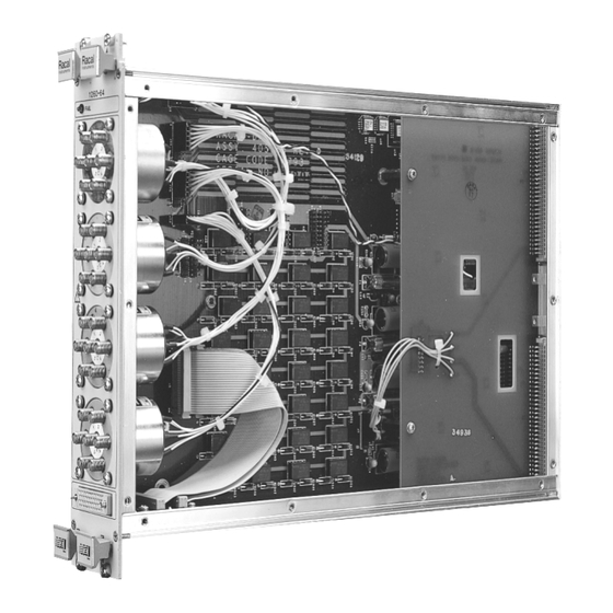
User Manual 1260-64 Chapter 1 MODULE SPECIFICATION The 1260-64 consists of up to four 1P6T, 18 6Hz switches and General two 1X16 switches. The 1x16 switches are intended to be used to drive external relays, although other applications are possible. -
Page 14: Specifications
User Manual 1260-64 Quantity of RF Switches Specifications 1260-64A 4 18GHz switches 1260-64B 2 18GHz switches 1260-64C 1 18GHz switch User Connectors on Module SMA - Caution: Mating Connector engagement should not exceed 9 in. lbs. torque maximum. Recommended Torque Wrench: Wiltron Model 01-201, 8in. -
Page 15: General
User Manual 1260-64 Sink Driver, VXI +24V Supply (External flyback-suppression diodes are required when switching inductive loads.) Maximum Total VXI Current Available to Drive External Loads +24V 5A (May be further limited by mainframe capability). +12V 5A (May be further limited... - Page 16 User Manual 1260-64 This page was left intentionally blank. Module Specification 1-4...
-
Page 17: Installation Instructions
3. Reship in either the original or a new, sturdy shipping carton. Installation of the Option 01 into the 1260-64 is described in the Option 01 Installation section of the 1260-Series VXI Switching Cards Installation Manual. -
Page 18: Lockout Keys
User Manual 1260-64 The lockout key configuration for the 1260-64 is slightly different Lockout Keys from that of the other 1260 modules because the 1260-64 occupies two VXI slots. Lockout key mounting holes are present in the front panel for each of the occupied VXI slots. - Page 19 User Manual 1260-64 The first consideration when configuring the relay banks is whether the bank is to act as a source driver or a sink driver. (A sink driver connects its output to ground to energize a load; a source connects its output to B+ to energize a load.) Eight push...
- Page 20 User Manual 1260-64 This page was left intentionally blank. Installation Instructions 2-4...
-
Page 21: Module Specific Syntax
User Manual 1260-64 Chapter 3 MODULE SPECIFIC SYNTAX The Module Specific Syntax for the 1260-64 is required for use in General the OPEN and CLOSE commands. It will also appear in data output by the 1260 Series Master in response to the PDATAOUT command. -
Page 22: Pdataout
OPEN 3.000,004-015,100-1 15,201,303 The PDATAOUT command causes the specified module to PDATAOUT transmit the CLOSED state of the relays in the 1260-64 module. The syntax used is: PDATAOUT <mod addr>[;<mod addr>][;<mod addr>]..The response to the PDATAOUT command for the 1260-64 is as follows: <header>... -
Page 23: Psetup
The supported sequence modes are IMM (Immediate), BBM (Break-Before-Make), and MBB (Make- Before-Break). The syntax used is: PSETUP <mod addr>[;<mod addr>][;<mod addr>]..The response to the PSETUP command for the 1260-64 is as follows: <header> <mod addr>.<seq mode>... - Page 24 S4) are always implemented as Break-Before-Make (BBM) to ensure that at most 1 of 6 relays are closed at any one time. The 1260-64 supports most standard 1260 features. These include Confidence Mode, Equate/Exclude/Scan Lists commands, and the STORE/RECALL commands.
-
Page 25: Connector Pin Configuration
Figure 4-1 shows the location of the four RF switches on the RF Relays front panel of the 1260-64 module. The designations for each of the SMA male connectors on the switches are also shown. Figure 4-2 shows the pin locations for the 50-pin Relay Bank Relay Banks connector, J1. -
Page 26: Figure 4-1, 1260-64 Front Panel
9 in . lb s . to rq u e m a xim u m . C O M C O M Figure 4-1, 1260-64 Front Panel Connector Pin Configuration 4-2... -
Page 27: Figure 4-2, Relay Bank Pin Configuration (J1)
User Manual 1260-64 Table 4-1, 1260-64 Pin Assignments BankA BankB Function Function A,C,E,H External B+ B,D,F,J External B+ X, y, z, AA External Ground CC,DD,EE External Ground z, AA, BB External Ground FF,HH External Ground Contact 0 Contact 0 Contact 1... -
Page 28: Figure 4-3, Internal Supply Sink Driver Example
User Manual 1260-64 +5 V +1 2V +2 4V E XT ER N A L B + E XT ER N A L GR OU N D E XT ER N A L R E LAY C O N TA C T 0... -
Page 29: Figure 4-5, Internal Supply Source Driver Example
User Manual 1260-64 + 5V + 12V + 24V E XT ER N A L B + E XT ER N A L G R O U N D C O N TA C T 0 C O N TA C T 1... - Page 30 User Manual 1260-64 This page was left intentionally blank. Connector Pin Configuration 4-6...
-
Page 31: Theory Of Operation
User Manual 1260-64 Chapter 5 THEORY OF OPERATION The 1260-64 consists of three PCB Assemblies. The smallest is PCB Assemblies used only to mount connector J 1 to the front panel. The other small PCB Assembly is required to pass the local bus signals, LBUSO through LBUS 11, through the unused second slot of this double-wide module. - Page 32 User Manual 1260-64 This page was left intentionally blank. Theory of Operation 5-2...
-
Page 33: Drawings
User Manual 1260-64 Chapter 6 DRAWINGS 407089, -001, -002, Final Assembly, 1260-64 ..............6-3 405055, PCB Assembly, L-BUS Bypass................6-4 435055, Schematic, L-BUS Bypass................... 6-5 405057 PCB Assembly, Connector Interface ..............6-6 435057 Schematic, Connector Interface ................6-7 405056, PCB Assembly, 1260-64..................6-8 435056, Schematic, 1260-64..................... - Page 34 User Manual 1260-64 This page was left intentionally blank. Drawings 6-2...
- Page 35 User Manual 1260-64 Drawings 6-3...
- Page 36 User Manual 1260-64 Drawings 6-4...
- Page 37 User Manual 1260-64 Drawings 6-5...
- Page 38 User Manual 1260-64 Drawings 6-6...
- Page 39 User Manual 1260-64 Drawings 6-7...
- Page 40 User Manual 1260-64 Drawings 6-8...
- Page 41 User Manual 1260-64 Drawings 6-9...
- Page 42 User Manual 1260-64 Drawings 6-10...
- Page 43 User Manual 1260-64 Drawings 6-11...
- Page 44 User Manual 1260-64 Drawings 6-12...
- Page 45 User Manual 1260-64 Drawings 6-13...
- Page 46 User Manual 1260-64 Drawings 6-14...
- Page 47 User Manual 1260-64 Drawings 6-15...
- Page 48 User Manual 1260-64 Drawings 6-16...
- Page 49 User Manual 1260-64 Drawings 6-17...
- Page 50 User Manual 1260-64 Drawings 6-18...
- Page 51 User Manual 1260-64 Drawings 6-19...
- Page 52 User Manual 1260-64 Drawings 6-20...
- Page 53 User Manual 1260-64 Drawings 6-21...
- Page 54 User Manual 1260-64 Drawings 6-22...
-
Page 55: Parts List
407089, Final Assembly, 1260-64A ................... 6-3 407089-001, Final Assembly, 1260-64B................6-4 407089-002, Final Assembly, 1260-64C................6-5 407090, Ship Kit, 1260-64 ....................6-6 405055, PCB Assembly, L-BUS Bypass................6-6 405057 PCB Assembly, Connector Interface ..............6-6 405056, PCB Assembly, 1260-64..................6-7 List of Suppliers ..................... - Page 56 User Manual 1260-64 This page was left intentionally blank. Parts List 7-2...
- Page 57 User Manual 1260-64 Parts List 7-3...
- Page 58 User Manual 1260-64 Parts List 7-4...
- Page 59 User Manual 1260-64 Parts List 7-5...
- Page 60 User Manual 1260-64 Parts List 7-6...
- Page 61 User Manual 1260-64 Parts List 7-7...
- Page 62 User Manual 1260-64 Parts List 7-8...
- Page 63 User Manual 1260-64 Parts List 7-9...
- Page 64 User Manual 1260-64 This page was left intentionally blank. Parts List 7-10...
-
Page 65: Optional Harness Assemblies
User Manual 1260-64 Chapter 8 OPTIONAL HARNESS ASSEMBLIES The following harness assemblies are used to connect Racal Instruments Model 1260-64 to Freedom Series Test Receiver Interfaces. Each harness documentation consists of an assembly drawing, parts list, system wire list, and wire list. - Page 66 User Manual 1260-64 This page was left intentionally blank. Optional Harness Assemblies 8-2...
- Page 67 User Manual 1260-64 Optional Harness Assemblies 8-3...
- Page 68 User Manual 1260-64 Optional Harness Assemblies 8-4...
- Page 69 User Manual 1260-64 Optional Harness Assemblies 8-5...
- Page 70 User Manual 1260-64 Optional Harness Assemblies 8-6...
- Page 71 User Manual 1260-64 Optional Harness Assemblies 8-7...
- Page 72 User Manual 1260-64 Optional Harness Assemblies 8-8...
- Page 73 User Manual 1260-64 Optional Harness Assemblies 8-9...
- Page 74 User Manual 1260-64 This page was left intentionally blank. Optional Harness Assemblies 8-10...
-
Page 75: Chapter 9 Product Support
For worldwide support and the office closes to your facility, refer to the Support Offices section on the following page. Use the original packing material when returning the 1260-64 to Reshipment Racal Instruments for calibration or servicing. The original... -
Page 76: Support Offices
User Manual 1260-64 Racal Instruments, Inc. Support Offices 4 Goodyear St., Irvine, CA 92618-2002 Tel: (800) RACAL-ATE, (800) 722-2528, (949) 859-8999; FAX: (949) 859-7139 Racal Instruments, Ltd. 480 Bath Road, Slough, Berkshire, SL1 6BE, United Kingdom Tel: +44 (0) 1628 604455; FAX: +44 (0) 1628 662017 Racal Systems Electronique S.A.
Need help?
Do you have a question about the 1260-64 and is the answer not in the manual?
Questions and answers