Table of Contents
Advertisement
Quick Links
MULTIPLEXER MODULE
Technologiepark Bergisch Gladbach, Friedrich-Ebert-Strasse, D-51429 Bergisch Gladbach, Germany
26 Ayer Rajah Crescent, 04-06/07 Ayer Rajah Industrial Estate, Singapore 0513.
Unit 5, 25F., Mega Trade Center, No 1, Mei Wan Road, Tsuen Wan, Hong Kong, PRC
Copyright 2001 by Racal Instruments, Inc. Printed in the United States of America. All rights reserved.
This book or parts thereof may not be reproduced in any form without written permission of the publisher.
1260 VXI
SWITCHING CARD
1260-50A/B
200MHz
PUBLICATION NO. 980673-015
RACAL INSTRUMENTS
Racal Instruments, Inc.
4 Goodyear St., Irvine, CA 92618-2002
Tel: (800) RACAL-ATE, (800) 722-2528, (949) 859-8999; FAX: (949) 859-7139
Racal Instruments, Ltd.
480 Bath Road, Slough, Berkshire, SL1 6BE, United Kingdom
Tel: +44 (0) 1628 604455; FAX: +44 (0) 1628 662017
Racal Systems Electronique S.A.
18 Avenue Dutartre, 78150 LeChesnay, France
Tel: +33 (1) 3923 2222; FAX: +33 (1) 3923 2225
Racal Systems Elettronica s.r.l.
Strada 2-Palazzo C4, 20090 Milanofiori Assago, Milan, Italy
Tel: +39 (0)2 5750 1796; FAX +39 (0)2 5750 1828
Racal Elektronik System GmbH.
Tel.: +49 2204 8442 00; FAX: +49 2204 8442 19
Racal Australia Pty. Ltd.
3 Powells Road, Brookvale, NSW 2100, Australia
Tel: +612 9936 7000, FAX: +612 9936 7036
Racal Electronics Pte. Ltd.
Tel: +65 7792200, FAX: +65 7785400
Racal Instruments, Ltd.
Tel: +852 2405 5500, FAX: +852 2416 4335
http://www.racalinstruments.com
PUBLICATION DATE: March 26, 2001
Advertisement
Table of Contents

Related Manuals for Racal Instruments 1260-50A


Summary of Contents for Racal Instruments 1260-50A
- Page 1 PUBLICATION DATE: March 26, 2001 Copyright 2001 by Racal Instruments, Inc. Printed in the United States of America. All rights reserved. This book or parts thereof may not be reproduced in any form without written permission of the publisher.
- Page 2 Authorization is required from Racal Instruments before you send us your product for service or calibration. Call your nearest Racal Instruments support facility. A list is located on the last page of this manual. If you are unsure where to call, contact Racal Instruments, Inc. Customer Support Department in Irvine, California, USA at 1-800-722-3262 or 1-949-859-8999 or via fax at 1-949-859-7139.
- Page 3 FOR YOUR SAFETY Before undertaking any troubleshooting, maintenance or exploratory procedure, read carefully the WARNINGS and CAUTION notices. This equipment contains voltage hazardous to human life and safety, and is capable of inflicting personal injury. If this instrument is to be powered from the AC line (mains) through an autotransformer, ensure the common connector is connected to the neutral (earth pole) of the power supply.
- Page 4 This page was left intentionally blank.
- Page 5 NOTE FOR SYSTEMS WITH 1260-OPT 01T The “Module-Specific Syntax” section of this manual shows the command syntax for the 1260-01S Smart Card. If you are using the newer 1260-01T Smart Card, the commands will NOT work as shown. Consult the 1260-01T Manual for a description of the commands that may be used with the 1260-01T Smart Card.
- Page 6 Control Information for the 1260-50A and –50C The following information describes the control-register-to-relay-channel mapping for a 1260-50A and 1260- 50C Relay Modules. This information may be used to control a 1260-50A (50C) when using a 1260-01T in the register-based mode of operation.
- Page 7 Channel Control Register Control Bit...
- Page 8 Control Information for the 1260-50B and –50D The following information describes the control-register-to-relay-channel mapping for a 1260-50B and 1260- 50D Relay Modules. This information may be used to control a 1260-50B (50D) when using a 1260-01T in the register-based mode of operation. Each relay on this module is controlled by setting or clearing a single bit within a Control Register.
- Page 9 Channel Control Register Control Bit...
-
Page 10: Table Of Contents
User Manual 1260-50A/B Table of Contents Chapter 1 INTRODUCTION .......................... 1-1 1260-50A/B 200MHz Multiplexer Module................... 1-1 Specifications ..........................1-3 Chapter 2 INSTALLATION INSTRUCTIONS....................2-1 Unpacking and Inspection ......................2-1 Reshipment Instructions ......................2-1 Option 01 Installation......................... 2-1 Module Installation........................2-1 Chapter 3 MODULE SPECIFIC SYNTAX ...................... - Page 11 User Manual 1260-50A/B List of Figures Figure 1-1, 1260-50A/B ........................ 1-1 Figure 1-2, 1260-50A/B Functional Diagram................. 1-2 Figure 1-3, 1260-50A/B Front Panel and J200-J203 Connector Pin Configuration ...... 1-5...
-
Page 12: Chapter 1 Introduction
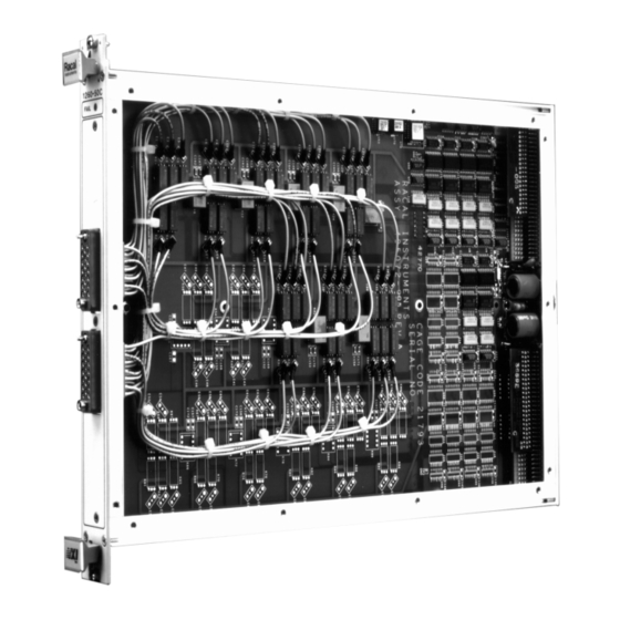
User Manual 1260-50A/B Chapter 1 INTRODUCTION The 1260-50A/B provides eight/sixteen 1 x 4 multiplexers (refer 1260-50A/B to the Functional Diagram Figure 1-2). Relays CHI9, 29,..., 159 200MHz provide for the connections between the adjacent I x 4 groups under software control. Thus, the 1260-50A/B module can be Multiplexer configured as multiplexers up to I x 39/1 x 79 size. - Page 13 CH 153 CH 32 CH 72 CH 112 CH 152 CH 31 CH 71 CH 111 CH 151 CH 30 CH 70 CH 110 CH 150 CH 129 CH 49 CH 89 1260-50A 1260-50B Figure 1-2, 1260-50A/B Functional Diagram Introduction 1-2...
-
Page 14: Specifications
User Manual 1260-50A/B Minimum Option 01 Firmware Revision 18.1 Specifications User Connector GMCT Series Crimp Shielded Contact from ERNI Maximum Switchable Voltage 200V DC/Peak AC (Signal to Ground) Resistive Load Maximum Switchable Current Per 0.5A DC/Peak AC Channel Resistive Load... - Page 15 User Manual 1260-50A/B Rise Time 1.6 ns (Typical I x 4 Multiplexer) Fall Time 1.6 ns (Typical 1 x 4 Multiplexer) Propagtion Delay Time 3 ns (Typical I x 4 Multiplexer) 39 ± 5mS Switching Time Cooling Requirements Airflow 4 litres / sec Backpressure 0.5 mm H...
- Page 16 User Manual 1260-50A/B R a cal R a cal Instrum ents Instrum ents 1260-50A 1260-50B FA IL FA IL Figure 1-3, 1260-50A/B Front Panel and J200-J203 Connector Pin Configuration Introduction 1-5...
- Page 17 User Manual 1260-50A/B This page was left intentionally blank. Introduction 1-6...
-
Page 18: Installation Instructions
Reship in either the original or a new shipping carton. Installation of the Option 01 to the 1260-50A/B is described in Option 01 the Installation section of the 1260 Series VXI Switching Cards Installation Manual. - Page 19 User Manual 1260-50A/B This page was left intentionally blank. Installation Instructions 2-2...
-
Page 20: Module Specific Syntax
Option 01 Operating Systems at Revision levels 18.1 and above. The 1260-50A/B RF Multiplexer supports the OPEN, CLOSE, PSETUP, RESET and PDATAOUT commands. The module specific syntax for the 1260-50A/B RF Multiplexer is Syntax as follows: OPEN <module address>.<channel>[ ;<module address> . <channel>J OPEN and CLOSE where <module address>... -
Page 21: Psetup
VXI Controller. The syntax used is: PSETUP <module address> [ ;<module address>) [;<module address>) where <module address> is the address. The responses to the PSETUP command for the 1260-50A/B multiplexer is as follows: 1260-50A: <module address>.1260-50A, 8 (1x4) 200 MHz MULTIPLEXER MODULE <module address>.B BM... - Page 22 User Manual 1260-50A/B Module Specific Syntax 3-3...
- Page 23 User Manual 1260-50A/B This page was left intentionally blank. Module Specific Syntax 3-4...
-
Page 24: Drawings
User Manual 1260-50A/B Chapter 4 DRAWINGS 407167-001, Final Assembly, 1260-50A................4-3 407167-002, Final Assembly, 1260-50B................4-4 405072-001, PCB Assembly, 1260-50A ................4-5 405072-002, PCB Assembly, 1260-50B ................4-6 435072, Schematic, 1260-50..................... 4-7 Drawings 4-1... - Page 25 User Manual 1260-50A/B This page was left intentionally blank. Drawings 4-2...
- Page 26 User Manual 1260-50A/B Drawings 4-3...
- Page 27 User Manual 1260-50A/B Drawings 4-4...
- Page 28 User Manual 1260-50A/B Drawings 4-5...
- Page 29 User Manual 1260-50A/B Drawings 4-6...
- Page 30 User Manual 1260-50A/B Drawings 4-7...
- Page 31 User Manual 1260-50A/B Drawings 4-8...
- Page 32 User Manual 1260-50A/B Drawings 4-9...
- Page 33 User Manual 1260-50A/B Drawings 4-10...
- Page 34 User Manual 1260-50A/B Drawings 4-11...
- Page 35 User Manual 1260-50A/B Drawings 4-12...
- Page 36 User Manual 1260-50A/B Drawings 4-13...
- Page 37 User Manual 1260-50A/B Drawings 4-14...
- Page 38 User Manual 1260-50A/B Drawings 4-15...
- Page 39 User Manual 1260-50A/B Drawings 4-16...
- Page 40 User Manual 1260-50A/B Drawings 4-17...
- Page 41 User Manual 1260-50A/B Drawings 4-18...
- Page 42 User Manual 1260-50A/B Drawings 4-19...
- Page 43 User Manual 1260-50A/B Drawings 4-20...
- Page 44 User Manual 1260-50A/B Drawings 4-21...
- Page 45 User Manual 1260-50A/B Drawings 4-22...
- Page 46 User Manual 1260-50A/B Drawings 4-23...
- Page 47 User Manual 1260-50A/B This page was left intentionally blank. Drawings 4-24...
-
Page 48: Parts List
Chapter 5 PARTS LIST 407167-001, Final Assembly, 1260-50A................5-3 407167-002, Final Assembly, 1260-50B................5-3 405072-001, PCB Assembly, 1260-50A ................5-4 405072-002, PCB Assembly, 1260-50B ................5-6 407216-001, Shipping Kit, 1260-50A ................. 5-9 407216-002, Shipping Kit, 1260-50B ................. 5-9 List of Suppliers....................... 5-10... - Page 49 User Manual 1260-50A/B This page was left intentionally blank. Parts List 5-2...
- Page 50 User Manual 1260-50A/B Parts List 5-3...
- Page 51 User Manual 1260-50A/B Parts List 5-4...
- Page 52 User Manual 1260-50A/B Parts List 5-5...
- Page 53 User Manual 1260-50A/B Parts List 5-6...
- Page 54 User Manual 1260-50A/B Parts List 5-7...
- Page 55 User Manual 1260-50A/B Parts List 5-8...
- Page 56 User Manual 1260-50A/B Parts List 5-9...
- Page 57 User Manual 1260-50A/B Parts List 5-10...
-
Page 58: Chapter 6 Product Support
For worldwide support and the office closes to your facility, refer to the Support Offices section on the following page. Use the original packing material when returning the 1260-50A/B Reshipment to Racal Instruments for calibration or servicing. The original... -
Page 59: Support Offices
User Manual 1260-50A/B Racal Instruments, Inc. Support Offices 4 Goodyear St., Irvine, CA 92618-2002 Tel: (800) RACAL-ATE, (800) 722-2528, (949) 859-8999; FAX: (949) 859-7139 Racal Instruments, Ltd. 480 Bath Road, Slough, Berkshire, SL1 6BE, United Kingdom Tel: +44 (0) 1628 604455; FAX: +44 (0) 1628 662017 Racal Systems Electronique S.A.
Need help?
Do you have a question about the 1260-50A and is the answer not in the manual?
Questions and answers