Alpha-InnoTec WZS Series Operating Manual
Brine/water heat pumps
Hide thumbs
Also See for WZS Series:
- Operating manual (52 pages) ,
- Operating manual (48 pages) ,
- Operating manual (48 pages)

Related Manuals for Alpha-InnoTec WZS Series


Summary of Contents for Alpha-InnoTec WZS Series
- Page 1 Brine/Water Heat Pumps Brine heat station Operating Manual WZS series 83056600eUK – Translation of the original operating manual...
-
Page 2: Table Of Contents
Table of contents 11 Maintenance ..........24 11.1 Basic principles ........24 11.2 Maintenance as required ......24 About this operating manual ...... 3 Validity ............3 condenser ..........24 Reference documents ....... 3 11.4 Yearly maintenance ......... 24 ..3 12 Faults .............. -
Page 3: About This Operating Manual
About this operating manual This operating manual is part of the unit. operating manual carefully and follow it for all Symbol Meaning activities at all times, especially the warnings and safety instructions. Safety-relevant information. Warning of physical injuries. Keep the operating manual to hand at the unit and hand over to the new owner if the unit changes DANGER Indicates imminent danger resulting... -
Page 4: Contact
All instructional information in this operating manual is this operating manual can be found on the internet at Germany: www.alpha-innotec.de www.alpha-innotec.com injuries and damage to property. Ensure that the personnel is familiar with the local... -
Page 5: Disposal
Improper action explosive atmospheres Requirements for minimum scale and corrosion damage in hot water heating systems: Constituents of antifreeze mixtures, e.g. ethanol, Proper planning, design and start-up atmosphere: Closed system with regard to corrosion mix antifreeze in well-ventilated rooms. Integration of adequately dimensioned pressure retention comply with the relevant safety regulations. -
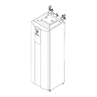
Page 6: Description
Unsuitable quality of the water in the domes- Description Ensure that the electrical conductivity of the 3.1 Layout NOTE This section essentially names Unsuitable quality of the water or the water- antifreeze mixture in the heat source described in this operating manual. hole heat exchanger (vertical collector) is not per- Housing with unit components mitted... - Page 7 Module box – variant without cooling 2 Heating circuit/hot water circulation pump 3 Heating element 4 3-way changeover valve, heating circuit/ domestic hot water 5 Valve motor 6 Position of rating plate 8 Venter 9 Electrical switch cabinet 11 Module box 12 Height-adjustable foot (4x) NOTE ing.
-
Page 8: Accessories
Module box – variant with cooling Control unit 1 Control panel 1 Compressor for data logging) 2 Condenser 3 Vibration isolator (4x) wall-mounted installation) 4 Lifting lug (4x) 5 Evaporator 6 Heat source circulation pump Underside of the control panel NOTE The hose connectors are not part of the scope of delivery with all KFE ball valves. -
Page 9: Function
Cooling a cooling function Cooling is integrated in type K units. Type H units can The following options are possible for units with cooling function ( operating manual of the heating and heat pump controller): 3.3 Function Passive cooling (without compressor) Liquid refrigerant is evaporated (evaporator), the energy for this process is environmental heat and Control of the cooling function via the heating and... -
Page 10: Delivery, Storage, Transport And Installation
Delivery, storage, transport 5.2 Storage and installation directly before installation. Store unit protected against: IMPORTANT Moisture/damp Damage to the housing and the unit components due to heavy objects. Frost Dust and dirt Do not place any objects on the unit which are heavier than 30 5.1 Scope of supply NOTE... - Page 11 Transport with a handcart NOTE NOTE If transporting with a handcart the module box must be pushed in. and dismantling the housing panels. shows transporting the unit on its left-hand side; it can also be transported on its right- damage the unit. hand side.
-
Page 12: Installation
5.4 Installation Installation and connection Installation room and space requirements 6.1 Dismantle the module box NOTE IMPORTANT Note and follow the local regulations and If the module box is tilted by more than 45°, standards regarding the installation room compressor oil runs into the cooling circuit. and space requirements. - Page 13 Unit without cooling: heat source. Unit without cooling: Unit with cooling: Unit with cooling: Disconnect the electrical connections: heat source (behind the covers). Disconnect 2 white connectors at the bot- tom of the electrical control cabinet. To do this, release the lugs by pressing on the sides of the connectors the top of the module box Subject to change without notice | 83056600eUK –...
- Page 14 Remove the insulation on the hydraulic connec- 10. Disconnect the hydraulic connections; to do this, tions. push the pipes apart as far as necessary. Remove 3 clips on the hydraulic connections. 11. Remove the 2 side retaining screws. Use spanner size SW 37 to unscrew the heating more easily: place boards under it, e.g.
-
Page 15: Install The Module Box
14. Slowly and carefully pull out the module box by 6.3 Install the hydraulic connections the carrying lugs . Ensure that none of the pipes are damaged NOTE 15. Pull out the module box completely and place it The heat source can be connected from the on the boards. -
Page 16: Connect The Electrical Cables
6.4 Connect the electrical cables IMPORTANT Tighten the union nut hand-tight and retighten Irreparable damage to the compressor due to the clamping ring is already in a clamping posi- tion. the compressor load infeed. Connect the unit to the heat source, domestic Basic information on the electrical connection water pipes and heating circuit NOTE... - Page 17 Route cables from underneath through the cable openings in the control box the connections Connect cables to the respective terminals Strip the sheathing of all cables to the external “Terminal diagram”, page 44). loads before laying in the cable duct of the control box.
-
Page 18: Installing The Control Panel
6.5 Installing the control panel Use cable ties ( in front of the connector (strain relief). NOTE The control can be inserted in a recess in the front panel of the unit or can be installed on the wall. Insert the control in the unit and connect 200 mm To do this, dismantle the front panel ( “Dismantle... -
Page 19: Remove The Front Panel Of The Module Box
Feed in the cables from the wall (e.g. in-wall box) or from below. Route the LIN bus cable from the top right-hand Remove the front panel of side at the rear from the heat pump and plug into the module box the control at the bottom. -
Page 20: Vent The Circulation Pump Of The Heat Source
If an antifreeze agent is not compatible with one 7.3 Vent the circulation pump of of these materials, it may not be used. the heat source Antifreeze agents from our product range are The front panel of the module box is unscrewed. safe with regard to our units and the accessories purchased from us and guarantee compatibility with the listed materials. -
Page 21: Domestic Hot Water Charging Circuit
Drain pipe of the safety valve is connected. domestic hot water charging The front panel of the module box is unscrewed. circuit Ensure that the set pressure of the safety valve is not exceeded. Heating water quality Pull the U-clip NOTE For detailed information refer, among 3-way changeover valve... -
Page 22: Insulate Hydraulic Connections
Position the valve motor on the 3-way change- Insulate hydraulic connections over valve Insert the U-clip Insulate heating circuit, heat source and domestic tor. water pipes according to the local regulations. Insulate the internal piping of the module box with included. -
Page 23: Commissioning
10 Commissioning NOTE NOTE The activities in this section are only nec- Relevant planning & design data of the system is the maximum return temperature can be documented in full. exceeded and the heat pump switches to high-pressure fault. of operation of the heat pump system. valve to the right to increase the tempera- System is air-free. -
Page 24: Maintenance
Arrange for the heat pump system to be commissioned by after-sales service authorised Swiss gas and water association (Schweizerischer by the manufacturer; this is a chargeable service. Verein des Gas- und Wasserverbands)): valve at the domestic cold water inlet. 11 Maintenance the hot water taps in the apartments. -
Page 25: Faults
12 Faults 12.2 circulating pumps NOTE If the safety temperature limiter on the manually. electric heating element has tripped, no fault is displayed. Read out the cause of the fault via the diagnostics circulation pump program of the heating and heat pump controller. Unscrew the front panel of the module box. -
Page 26: Dismantling And Disposal
13 Dismantling and Disposal 13.1 Dismantling Unit is safely disconnected from the power supply again. Collect all media safely. Separate components by their materials. 13.2 Disposal and Recycling Dispose of media harmful to the environment according to local regulations, e.g. antifreeze mixture, refrigerant.
Need help?
Do you have a question about the WZS Series and is the answer not in the manual?
Questions and answers