
Subscribe to Our Youtube Channel
Related Manuals for Alpha-InnoTec WZS 42K3M


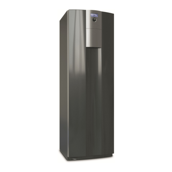
Summary of Contents for Alpha-InnoTec WZS 42K3M
- Page 1 Brine/water heat pumps Operating Manual WZS series 83056600cUK – Translation into English of the original German operating manual...
- Page 2 Contents 11 Maintenance ...............22 11.1 Basic principles ............22 11.2 Maintenance as required ........22 About this operating manual ........ 3 11.3 Yearly maintenance ..........22 Validity ................3 11.4 Clean and flush the evaporator and Reference documents ..........3 condenser ..............22 1.3 Symbols and identification markings ....3 12 Faults Contact ..................23 ................
-
Page 3: About This Operating Manual
About this operating manual 1.3 Symbols and identification markings This operating manual is part of the unit. Identification of warnings ► Before working on or with the unit read the operating manual carefully and follow it for all Symbol Meaning activities at all times, especially the warnings and safety instructions. -
Page 4: Residual Risks
1.4 Contact ► Only allow skilled personnel to do any other work on the system, e.g. Addresses for purchasing accessories, for service – Heating installer cases or for answers to questions about the unit and this operating manual can be found on the internet at – Plumbing installer any time and is kept up to date: –... -
Page 5: Avoid Damage To Property
Injuries and environmental damage due to ● Material fatigue refrigerant ● bubbles cushion formation (cavitation) The unit contains harmful and environmentally danger- ous refrigerant. If refrigerant leaks from the unit: ● Negative effect on heat transfer, e.g. formation of coatings, deposits, and associated noises, e.g. Switch off unit. boiling noises, flow noises Thoroughly ventilate installation room. - Page 6 Description 3-way changeover valve, heating circuit/domestic hot water Valve motor 3.1 Layout Venter Position of rating plate NOTE 5 Overflow valve This section essentially names Electrical switch cabinet components relevant for fulfilling the tasks described in this operating manual. 7 Domestic hot water tank sensor Module box Heat station Height-adjustable foot (4x)
- Page 7 Module box, variant without cooling Module box, variant with cooling Compressor Compressor Condenser Condenser Vibration isolator (4x) Vibration isolator (4x) Lifting lug (4x) Lifting lug (4x) Evaporator Evaporator Heat source circulation pump Heat source circulation pump 7 Heat source filling and drain tap 7 Heat source filling and drain tap 8 Heating filling and drain tap 8 Heat source filling and drain tap 9 Heating filling and drain tap...
-
Page 8: Function
3.2 Accessories Control unit The following accessories are available for the unit through the manufacturer's local partner: ● Additional cover for the front cover panel, if the control unit is mounted on the wall ● Room thermostat for switching the cooling function (if available) ●... -
Page 9: Maintenance
Delivery, storage, Cooling transport and installation Cooling is integrated in type K units. Type H units can be retrofitted with the “Cooling package” accessories. The following options are possible for units with cooling function ( operating manual of the heating 5.1 Scope of supply and heat pump controller): ●... -
Page 10: Unpacking And Transport
5.3 Unpacking and transport Dismantle housing panels for transport with handcart or carrying the unit Notes on safe transport Unit is unpacked ( “Unpacking” on page 10). The heating station and the module box are heavy To avoid damage to the housing panels: ( “Technical data/Scope of supply” on page 24). –... -
Page 11: Installation
To avoid damage: On a handcart, load the unit on Refrigerant capacity [kg] Minimum room volume = its side only. Limit value [kg/m³] NOTE If several heat pumps of the same type are installed only one heat pump need to be taken into account. If several heat pumps of different types are installed, only the heat pump with the largest refrigerant volume needs to be taken into account. - Page 12 Remove the front panel of the module box ► Unit with cooling: ( “7.1 Remove the front panel of the module box” on page 18). Close shut-off valves to the heating circuit. Use a spanner to close the shut-off valves of the heat source (behind the covers).
- Page 13 Drain the unit via the filling and drain tap of the Disconnect the electrical connections. heat source. – Disconnect 2 white connectors (1) at the bottom of the electrical control cabinet. To do ► Unit without cooling: this, release the latching lugs by pressing on the sides of the connectors.
- Page 14 Remove 3 clips on the hydraulic connections. 11. Remove the 2 side retaining screws. 12. To protect the floor and move the module box (3) Use spanner size SW 52 to unscrew the heating more easily: place boards (4) under it, e.g. from flow. the packaging material. 13. Lift and hold nut (1) on the heating flow. 14. Slowly and carefully pull out the module box by the retaining loops (2).
-
Page 15: Installing The Module Box
6.3 Install the hydraulic connections 15. Pull out the module box completely and place it on the boards. ATTENTION Damage to the copper pipes due to unacceptable loading! ► Secure all connections against twisting. NOTE The heat source can be connected from the top, right or left. -
Page 16: Connect The Electrical Cables
Basic information on the electrical connection If the connection leaks: Undo connection and check pipe for damage. NOTE Tighten the union nut hand-tight and retighten with Ensure that the unit is supplied with electricity the open-ended spanner with 1/8 to 1/4 turn, as at all times. After working inside the unit and the clamping ring is already in a clamping position. attaching the unit panelling, switch the power supply back on immediately. -
Page 17: Installing The Control Unit
6.5 Installing the control unit Lay the control / sensor cables and unit supply cable and connect: – Route cables through the reserve conduits (1) NOTE and (2) only, from above into the inside of the The control unit can be inserted in a recess in unit. -
Page 18: Flushing, Filling And Venting
Flushing, filling and venting Mount the control unit on the wall and connect Release the rear bracket from the control unit. 7.1 Remove the front panel of the Cut off latching lugs (if visually obtrusive). module box Mark 2 drillholes ( “Dimensioned drawing of ► Unscrew the front panel of the module box. control unit, wall-mounted bracket” on page 34). -
Page 19: Fill, Flush And Vent Heat Source
7.4 Vent the circulation pump Advantages of low-salt operation: of the heat source ● Low corrosion-promoting properties ● No formation of mineral scale NOTE ● Ideal for closed heating circuits The diagram shows the unit variant with ● ideal pH value due to self-alkalinisation after filling cooling. -
Page 20: Flush And Fill The Heating And Domestic Hot Water Charge Circuit
7.5 Flush and fill the heating and Insert the U-clip (2) into the floor of the valve motor. domestic hot water charge circuit Drain pipe of the safety valve is connected. ► Ensure that the set pressure of the safety valve is not exceeded. Pull the U-clip (2) off the floor of the valve motor (1). -
Page 21: Insulate Hydraulic Connections
Insulate hydraulic Turn the adjusting knob (2) of the overflow valve (1) until the temperature drop between the flow connections and return temperature is set as follows: – at heat source temperature 0 °C: 8 K Insulate heating circuit, heat source and domestic –... -
Page 22: Basic Principles
► Ensure compliance with local regulations with – The power supply for the heat pump is regard to the specific heat pump system. equipped with an all-pole miniature circuit- breaker with at least 3 mm contact spacing (IEC 60947-2). 11.2 Maintenance as required – The level of the tripping current is compliant. ●... -
Page 23: Contact ............................................................................. 4
12 Faults 13 Dismantling and Disposal NOTE 13.1 Dismantling If the safety temperature limiter on the electric Unit is safely disconnected from the power supply heating element has tripped, no fault is and protected against being switched back on displayed. - Page 24 Technical data/Scope of supply WZS 42(H)(K)3M – WZS 102(H)(K)3M Leistungsdaten Heizleistung / COP Leistungsdaten Heizleistung / COP WZS 42(H)(K)3M WZS 62(H)(K)3M Performance data: Heating output / COP SW 232H3 bei B0/W35 Normpunkt nach EN14511 bei B0/W35 Normpunkt nach EN14511 kW ı COP 4,70 ı...
- Page 25 Performance data: Heating output / COP Leistungsdaten Heizleistung / COP Leistungsdaten Heizleistung / COP WZS 82(H)(K)3M SW 232H3 WZS 102(H)(K)3M at B0/W35 operating point to EN14511 bei B0/W35 Normpunkt nach EN14511 bei B0/W35 Normpunkt nach EN14511 kW ı COP kW ı COP 22.35 ı...
- Page 26 WZS 122(H)(K)3M Performance data: Heating output / COP Leistungsdaten Heizleistung / COP WZS 122(H)(K)3M SW 232H3 at B0/W35 operating point to EN14511 bei B0/W35 Normpunkt nach EN14511 kW ı COP kW ı COP 22.35 ı 4.95 12,18 ı 5,00 at B0/W45 operating point to EN14511 bei B0/W45 Normpunkt nach EN14511 kW ı...
- Page 27 Subject to change without notice | 83056600cUK – Translation into English of the original German operating manual | ait-deutschland GmbH...
- Page 28 WZS 42(H)(K)3M Performance curves Qh (kW) Temp„ (°C) Pe (kW) 35°C 45°C 55°C 65°C Temp„ (°C) Temp„ (°C) ∆p„ (bar) ∆p” (bar) Δp„ Δp” Δp Δp HW/K WQ/K “” (m³/h) “„ (m³/h) 823234 Legende: “” Volumenstrom Heizwasser “„ Volumenstrom Wärmequelle Temp„ Temperatur Wärmequelle Heizleistung Leistungsaufnahme Coeffiicient of performance / Leistungszahl...
-
Page 29: Performance Curves
WZS 62(H)(K)3M Performance curves Qh (kW) Temp„ (°C) Pe (kW) 35°C 45°C 55°C 65°C Temp„ (°C) Temp„ (°C) ∆p„ (bar) ∆p” (bar) Δp„ Δp” Δp Δp WQ/K HW/K “” (m³/h) “„ (m³/h) 823235 Legende: “” Volumenstrom Heizwasser “„ Volumenstrom Wärmequelle Temp„ Temperatur Wärmequelle Heizleistung Leistungsaufnahme Coeffiicient of performance / Leistungszahl... - Page 30 Performance curves WZS 82(H)(K)3M Qh (kW) Temp„ (°C) Pe (kW) 35°C 45°C 55°C 65°C Temp„ (°C) Temp„ (°C) ∆p„ (bar) ∆p” (bar) Δp„ Δp” Δp Δp WQ/K HW/K “” (m³/h) “„ (m³/h) 823236 Legende: “” Volumenstrom Heizwasser “„ Volumenstrom Wärmequelle Temp„ Temperatur Wärmequelle Heizleistung Leistungsaufnahme Coeffiicient of performance / Leistungszahl...
- Page 31 Performance curves WZS 102(H)(K)3M Qh (kW) Temp„ (°C) Pe (kW) 35°C 45°C 55°C 65°C Temp„ (°C) Temp„ (°C) ∆p„ (bar) ∆p” (bar) Δp„ Δp” Δp Δp WQ/K HW/K “” (m³/h) “„ (m³/h) 823327 Legende: “” Volumenstrom Heizwasser “„ Volumenstrom Wärmequelle Temp„ Temperatur Wärmequelle Heizleistung Leistungsaufnahme Coeffiicient of performance / Leistungszahl...
- Page 32 Performance curves WZS 122(H)(K)3M Qh (kW) Temp„ (°C) Pe (kW) 35°C 45°C 55°C 65°C Temp„ (°C) Temp„ (°C) ∆p„ (bar) ∆p” (bar) Δp„ Δp” Δp WQ/K Δp HW/K “” (m³/h) “„ (m³/h) 823238 Legende: “” Volumenstrom Heizwasser “„ Volumenstrom Wärmequelle Temp„ Temperatur Wärmequelle Heizleistung Leistungsaufnahme Coeffiicient of performance / Leistungszahl...
-
Page 33: Dimensioned Drawings
Dimensioned drawings ↑↓ ↑ ↓ >250 >250 Item Name Dim. Heating water outlet (flow) Ø28 Outside diameter Pos. Bezeichnung Dim. Heat source inlet (in heat pump) optionally at Ø28 the top, on the right or left Outside diameter Ø28 Heizwasser Austritt (Vorlauf) Aussendurchmesser Key: D819451 Heating water inlet (return) - Page 34 Dimensioned drawing of control unit, wall-mounted bracket Schutzvermerk ISO 16016 beachten Schutzvermerk ISO 16016 beachten Wall mounted Bohrschablone Blattformat: A4 hoch Maßstab Det. Maßstab Allgemein- Oberflächen toleranz Werkstoff Gewicht Datum Name Benennung Maßbild WZS 18.11.2014 Brueckner Erstellt Gepr. Norm. Ø6 Ø6 ait-deutschland GmbH ArtikelNr. Blatt 819447 Industriestraße 3 D - 95359 Kasendorf PEP 015-2014...
-
Page 35: Heating Circuit
Dimensioned drawing of connections Heating circuit Rp 5/4" Rp 1" Heating source Rp 5/4" Rp 1" Rp 1" Ø28 Ø28 Ø35 Ø28 Ø28 Ø35 Allgemein- toleranz DIN ISO 2768 -cL Datum 20.10.2015 E Erstellt Gepr. Norm. ait-deutschla Industriest Maß Allgemein- Oberflächen D - 95359 K Blattformat: A3 quer... -
Page 36: Installation Plans
Installation plans 1000 > 1 Key: DE819448 V1 Version 1 FS Free space for service purposes FZ Free space for functionally Legende: DE819448 necessary accessories Version 1 OKF Finished floor level Rh min. Raumhöhe Minimum Freiraum für Servicezwecke Freiraum für funktionsnotwendiges Zubehör Oberkante Fertigfussboden All dimensions in mm. - Page 37 Installation plans 1000 > 1 Key: DE819448 V2 Version 2 FS Free space for service purposes FZ Free space for functionally Legende: DE819448 necessary accessories Version 2 Rh min. Raumhöhe Minimum OKF Finished floor level Freiraum für Servicezwecke Freiraum für funktionsnotwendiges Zubehör Oberkante Fertigfussboden All dimensions in mm.
- Page 38 Installation plans > 600 > 1 > 1 Key: DE819448 V3 Version 3 FS Free space for service purposes Legende: DE819448 OKF Finished floor level Version 3 Rh min. Raumhöhe Minimum Freiraum für Servicezwecke Oberkante Fertigfussboden 1000 All dimensions in mm. Alle Maße in mm. Subject to change without notice | 83056600cUK –...
- Page 39 Hydraulic integration, unit variant H (heating) Subject to change without notice | 83056600cUK – Translation into English of the original German operating manual | ait-deutschland GmbH...
- Page 40 Hydraulic integration, separate buffer tank Subject to change without notice | 83056600cUK – Translation into English of the original German operating manual | ait-deutschland GmbH...
- Page 41 Hydraulic integration, unit variant K (cooling) Subject to change without notice | 83056600cUK – Translation into English of the original German operating manual | ait-deutschland GmbH...
- Page 42 Subject to change without notice | 83056600cUK – Translation into English of the original German operating manual | ait-deutschland GmbH...
- Page 43 WZS 42(H)(K)3M – WZS 122(H)(K)3M Terminal diagram 1~N/PE/230V/50Hz 3~PE/400V/50Hz 3~N/PE/400V/50Hz OUT4 OUT5 OUT6 OUT7 OUT8 OUT9 OUT10 OUT11 OUT12 OUT13 OUT14 OUT15 OUT16 OUT17 NTC6 NTC7 NTC8 TRL ext. NTC9 NTC10 NTC11 NTC12 NTC13 NTC14 NTC15 Subject to change without notice | 83056600cUK – Translation into English of the original German operating manual | ait-deutschland GmbH...
- Page 44 WZS 42(H)(K)3M – WZS 82(H)(K)3M Circuit diagram 1/3 Subject to change without notice | 83056600cUK – Translation into English of the original German operating manual | ait-deutschland GmbH...
- Page 45 Circuit diagram 2/3 WZS 42(H)(K)3M – WZS 82(H)(K)3M OUT1 OUT6 OUT17 PWM1 PWM2 OUT14 OUT13 Subject to change without notice | 83056600cUK – Translation into English of the original German operating manual | ait-deutschland GmbH...
- Page 46 WZS 42(H)(K)3M – WZS 82(H)(K)3M Circuit diagram 3/3 NTC11 blue NTC9 brown / blue white green yellow pink NTC12 NTC13 NTC14 NTC15 white / blue grey / brown pink / brown violet grey / pink Black red / blue white / green Orange Yellow /2.D7...
- Page 47 Circuit diagram 1/3 WZS 102(H)(K)3M – WZS 122(H)(K)3M Subject to change without notice | 83056600cUK – Translation into English of the original German operating manual | ait-deutschland GmbH...
- Page 48 WZS 102(H)(K)3M – WZS 122(H)(K)3M Circuit diagram 2/3 OUT1 OUT6 OUT17 PWM1 PWM2 OUT14 OUT13 Subject to change without notice | 83056600cUK – Translation into English of the original German operating manual | ait-deutschland GmbH...
- Page 49 Circuit diagram 3/3 WZS 102(H)(K)3M – WZS 122(H)(K)3M NTC11 blue NTC9 brown / blue white green yellow pink NTC12 NTC13 NTC14 NTC15 white / blue grey / brown pink / brown violet Black grey / pink red / blue Orange white / green Yellow /2.D7...
- Page 50 Subject to change without notice | 83056600cUK – Translation into English of the original German operating manual | ait-deutschland GmbH...
- Page 51 10067141 WZS 82H3M 10066241 WZS 82H3M 10067241 WZS 102H3M 10066342 WZS 102H3M 10067342 WZS 122H3M 10066442 WZS 122H3M 10067442 WZS 42K3M 10066541 WZS 42K3M 10067541 WZS 62K3M 10066641 WZS 62K3M 10067641 WZS 82K3M 10066741 WZS 82K3M 10067741 WZS 102K3M 10066842...
- Page 52 GmbH Industriestraße 3 D-95359 Kasendorf E info@alpha-innotec.de W www.alpha-innotec.de alpha innotec – an ait-deutschland GmbH brand...
Need help?
Do you have a question about the WZS 42K3M and is the answer not in the manual?
Questions and answers