
Related Manuals for Alpha-InnoTec WWB 20


Summary of Contents for Alpha-InnoTec WWB 20
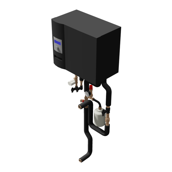
- Page 1 Domestic hot water heat Pumps Operating Manual WWB 20 83052900fUK – Translation into English of the original German operating manual...
-
Page 2: Please Read First
Please read first Symbols This operating manual provides important information The following symbols are used in the operating manual. on handling the unit. It is an integral part of the product They have the following meaning: and must be kept ready to hand in the immediate vicinity of the unit. -
Page 3: Table Of Contents
Contents INFORMATION FOR USERS AND QUALIFIED INFORMATION FOR USERS AND QUALIFIED PERSONNEL PERSONNEL PLEASE READ FIRST ..............2 CONTROLLER DESCRIPTION SYMBOLS ..................2 The control panel ...............18 INTENDED USE ................5 Status display ...............18 DISCLAIMER................5 Screen ...................18 EC CONFORMITY ..............5 “Turn/push knob” ..............18 Error messages ..............19 SAFETY ..................5 Screen display language ............19... - Page 4 Remote maintenance ............43 Switch on the remote maintenance function ....44 Set the remote maintenance function ......44 Information about the remote maintenance function ..45 Set the remote maintenance function ......45 Manual data transfer ............46 ERROR DIAGNOSIS / ERROR MESSAGES ......47 TECHNICAL DATA ..............50 Installation ................50 Outputs ................50...
-
Page 5: Intended Use
Intended use Safety The unit is to be used solely for its intended purpose. The unit is safe to operate for its intended use. The de- This means: sign and workmanship of the unit conform to current state of the art standards, all relevant DIN/VDE regula- •... -
Page 6: Customer Service
, hydraulic requirements, manufacturer's specifica- tions and the relevant regulations, the WWB 20 can be used in new or existing domestic hot water systems for For a current list and additional partners of the manufac- domestic water heating. -
Page 7: Maintenance Of The Unit
Maintenance of the unit Scope of supply The cooling circuit of the heat pump requires no regu- Included in the scope of supply: lar maintenance. According to EU regulation (EC) 517/2014, leak inspections and maintenance of a log book are required by law for certain heat pumps! Log book for heat pumps, Section “Information on use of the log book”. -
Page 8: Installation Packages
2 corrugated stainless steel pipes with seals and insulation for connecting the WWSB 202 to the WWB 20 (both sides with union nuts 1”) Subject to change without notice | 83052900fUK – Translation into English of the original German operating manual | ait-deutschland GmbH... -
Page 9: Installation
Installation TRANSPORT TO INSTALLATION LOCATION During transport always note and comply with the fol- The following applies to all work to be done: lowing instructions: NOTE. ATTENTION Always comply with the relevant local accident Never use components and hydraulic connec- prevention regulations, statutory regulations, tions on the unit for transport purposes. - Page 10 and removing the front cover: Fix the housing onto the wall using 4 bolts (provid- ed on site) pushed through the holes in the rear of the unit: 1 Screws for transport safeguard 2 Handle positions Interior view of housing Remove the two screws of the transport safeguard Push the internal part completely into the housing.
-
Page 11: Installing The Hydraulic Connections
Installing the hydraulic DOMESTIC HOT WATER TANK connections You must integrate a special domestic hot water tank system. Choose the storage volume so that the required quantity of domestic hot water is available. The heat exchanger surface of the domestic hot water tank must be dimensioned so that the heating capacity of the heat pump is transferred with minimum spread. -
Page 12: Electrical Connection Work
Electrical connection work To access the switch box, the control panel with the controller circuit board must be completely tilt- ed forwards: The following applies to all work to be done: DANGER! Risk of fatal electric shock! All electrical connections must be carried out by qualified electricians only. - Page 13 ... press on and lock with the quick-release screws (turn 90° clockwise). 1 Switchbox open. Plan view 2 Domestic hot water sensor connection 3 Controller board 4 Load and control voltage connection ATTENTION The power supply for the heat pump must be fit- ted with a miniature circuit-breaker with at least 3 mm contact gap to IEC 60947-2.
-
Page 14: Flushing And Filling The System
Flushing and filling the system DAMAGE THAT CAN OCCUR IN CASE OF FAILURE TO COMPLY WITH THE ABOVE - Malfunctions and the failure of components (e.g. pumps, WATER QUALITY FOR HEAT SOURCE AND valves) DOMESTIC HOT WATER CHARGING CIRCUIT - Internal and external leaks (e.g. from heat exchangers) OF THE FILL AND TOP-UP WATER IN WATER HEATING - Cross-section reduction and blockage of components (e.g. -
Page 15: Flushing, Filling And Bleeding The Heat Source And Domestic Hot Water Charging Circuit
FLUSHING, FILLING AND BLEEDING THE HEAT SOURCE Part 2 of VDI 2035 also refers to the reduction in total salt content (conductivity). The risk of corrosion is far AND DOMESTIC HOT WATER CHARGING CIRCUIT lower if deionised water is used than is the case if the system is operated with salty, i.e. -
Page 16: Flushing, Filling And Bleeding The Domestic Hot Water Circuit
FLUSHING, FILLING AND BLEEDING THE DOMESTIC HOT WATER CIRCUIT ATTENTION The electrical conductivity of the domestic hot water must be > 100 µS/cm and lie within the required drinking water quality. ATTENTION Before flushing and filling the domestic hot water tank, the drain pipe of the safety valve must be connected. -
Page 17: Insulating The Hydraulic Connections
Dismantling Insulating the hydraulic connections DANGER! Risk of fatal electric shock! Check all hydraulic connections for leaks. Perform Electrical work may only be carried out by leak test… qualified electricians. Insulate all connections, vibration isolation devic- Before opening the unit, safely disconnect es, connections and pipes of the domestic hot water the system from the power supply and charging circuit and the heat source. -
Page 18: Controller Description
Controller description The control panel Select the navigation arrow to switch from one menu level to the next higher or lower one. Some menus require the settings made to be saved. To do this, select . To cancel settings made, select If a menu has more entries than the screen can display, a scroll bar appears on the left side of the screen. -
Page 19: Error Messages
ERROR MESSAGES If a fault occurs in the system, a corresponding error message appears in the screen. ATTENTION Before acknowledging a fault, always read the “Error Diagnosis / Error Messages“ and “Ac- When the heat pump is switched on for the first time knowledging a Fault”... -
Page 20: The Navigation Screen
The Navigation screen Program area “Info and Setting” The navigation screen provides an overview of the differ- ent program areas of the domestic hot water and heat pump controller. BASIC DISPLAY SETTING THE DOMESTIC WATER HEATING MODE 1 Current operating state of the heat pump In the navigation screen, select the symbol... -
Page 21: Setting The Domestic Hot Water Temperature
4 Holidays SETTING THE DOMESTIC HOT WATER TEMPERATURE Domestic water heating is switched off with imme- diate effect until the set date expires or until another In the “Domestic hot water quick settings” menu, mode is selected manually. select the menu bar heading “Setpoint – > ”… 5 Second heat generator Programmed switching times control the domestic water heating without the heat pump. -
Page 22: Program Area "Domestic Hot Water
Program area SELECT PROGRAM AREA “Domestic hot water” In the navigation screen, select the symbol... NOTE. If a domestic hot water temperature is set, which cannot be achieved, the heat pump ini- tially switches to “High pressure fault”. This is followed by a self-resetting fault. -
Page 23: Setting "Domestic Water Heating" Mode
SETTING “DOMESTIC WATER HEATING” MODE SET THE DOMESTIC HOT WATER TEMPERATURE In the menu “Domestic hot water settings” menu, NOTE select the “Mode” menu field… If the domestic water heating is controlled by a thermostat, temperature setting is not pos- sible. -
Page 24: Domestic Water Heating Timing Program
DOMESTIC WATER HEATING TIMING PROGRAM SAME SWITCHING TIMES FOR ALL DAYS OF THE WEEK You can define a maximum of three time periods with- NOTE. in 24 hours, during which the domestic hot water is to be switched off. The defined time periods apply to eve- When programming, note that the time periods, ry day of the week. - Page 25 DIFFERENT SWITCHING TIMES DURING THE WEEK NOTE. AND AT THE WEEKEND If the time period is set as 00:00 – 00:00, do- mestic water heating is generally enabled. You can define a maximum of 5 periods, during which hot water is to be switched off, for each of the two groups of days: Monday –...
- Page 26 DIFFERENT SWITCHING TIMES EACH DAY QUICK CHARGE You can define a maximum of 5 time periods for each If you need domestic hot water despite active off time(s), day, during which the domestic hot water is to be you can use the “Quick charge” function to bypass the switched off.
- Page 27 MAINTENANCE PROGRAMS NOTE. “Continuous operation” means that thermal dis- In the “Domestic hot water settings” menu, select infection follows each period of domestic water the “Maintenance programs” menu field… heating. However, domestic hot water charging always starts at the set hysteresis of the domes- tic hot water setpoint.
- Page 28 Example 2: The circulation pump can be configured by setting switching times and cycle times. 10 min 10 min 10 min 10 min 5 min 5 min 5 min 5 min In the switching times, enter the times during which the circulation pump is to run.
-
Page 29: Program Area "Service
Program area “Service” RETRIEVE TEMPERATURES In the “Service Information” menu select the “Tem- peratures” menu field… SELECT PROGRAM AREA In the navigation screen, select the symbol... The screen switches to the “Service information - temperatures” menu. The screen switches to the “Service” menu. Hot gas Hot gas temperature Domestic water-Actual Domestic hot water Actual... -
Page 30: Retrieve Inputs
RETRIEVE INPUTS RETRIEVE OUTPUTS In the “Service Information” menu, select the “In- In the “Service Information” menu, select the “Out- puts” menu field. puts” menu field. The screen switches to the “Service information - The screen switches to the “Service information - outputs”... -
Page 31: Retrieve Running Times
RETRIEVE RUNNING TIMES RETRIEVE OPERATING HOURS In the “Service information” menu, select the “Run- In the “Service Information” menu, select the “Op- ning times” menu field… erating hours” menu field. The screen switches to the “Service information - operating hours” menu. The screen switches to the “Service information running times”... -
Page 32: Retrieve Error Memory
RETRIEVE ERROR MEMORY RETRIEVE SHUTDOWNS In the “Service information” menu, select the “Er- In the “Service information” menu, select the “Shut- ror memory” menu field… downs” menu item… The screen switches to the “Service information - The screen switches to the “Service information - stored errors”... -
Page 33: Retrieve System Status
RETRIEVE SYSTEM STATUS BACNET In the “Service information” menu, select the “Sys- In the “Service information” menu, select the “BAC- tem status” menu item… net” menu field… The screen switches to the “Service information - The screen switches to the “BACnet” menu… system status”... -
Page 34: Setting
Setting The screen switches to the “Service settings - pass- word” menu… In the “Service” menu, select the “Settings” menu field. 1 Symbol for “Service settings” program area with menu heading 2 Input fields for four-digit numeric code 3 Information on the current status of the data The screen switches to the “Service settings”... -
Page 35: Open Short Programs
OPEN SHORT PROGRAMS DEFINE TEMPERATURES The short programs are intended to make service work In the “Service settings” menu, select the “Temper- easier. atures” menu field… In the “Settings” menu, select the “Short programs” The screen switches to the “Service settings - tem- menu field…... -
Page 36: Defining The System Setting
DEFINING THE SYSTEM SETTING EVU off EVU off times without ZWE = ZWE also off during EVU off In the “Service settings” menu, select the “System with ZWE = ZWE enabled while EVU off setting” menu field… Setting only takes effect if ZWE is boiler or combination boiler. -
Page 37: Venting (Bleeding) The System
Access Data access authorisation BOSUP fan Fan, well or brine circulation pump The “Fitter” setting (= Qualified personnel) can be used to change, without a password, MA1 / MA2 / MA3 all parameters, which can otherwise only be Mixer 1, Mixer 2, Mixer 3 OPEN changed with “KD”... -
Page 38: Set Ibn Parameters
You can also save the settings data on an external USB SET IBN PARAMETERS stick. You can save the settings made during commissioning (= set IBN parameters). If necessary, this enables you to quickly and easily reset the system to its commission- ing status. -
Page 39: Define Date And Time
DEFINE DATE AND TIME IBN WIZARD In the “Service” menu, select the “Date and Time” menu field… The control is equipped with a commissioning (IBN) or startup wizard. This wizard guides you through the con- troller's most important settings during the initial start- up. -
Page 40: Restore Ibn Parameters
RESTORE IBN PARAMETERS DATA LOGGER If your heat pump was commissioned by an authorised The control has a data logger, which records the heat customer service partner and they saved the commis- pump data for a period of 48 h. (Temperatures, inputs, sioning parameters, you can use this menu item to re- outputs) store them. -
Page 41: Web Server
SET THE CONTRAST OF THE CONTROL PANEL DISPLAY WEB SERVER You can adjust the contrast of the control panel display NOTE. to your needs. The left-hand socket on the underside of the Scroll down the “Service” menu and select the “Sys- control panel can be used to connect to a com- tem control”... -
Page 42: Dhcp Client
DHCP CLIENT The screen switches to the “System control” menu. Here, select the “Web server” menu item... If the heat pump controller is connected to a network with a DHCP server, this server (e.g. router) can assign an IP address to the controller. To do this, the DHCP client item must be activated. -
Page 43: Remote Maintenance
REMOTE MAINTENANCE If the “DHCP server” or “DHCP client” is activat- ed, data cannot be changed here, only read out. The computer connected as a DHCP client is auto- NOTE matically assigned an IP address. To access the domestic hot water and heat pump In order to use the “Remote maintenance”, the controller from the connected computer, open an following requirements must be fulfilled:... -
Page 44: Switch On The Remote Maintenance Function
SWITCH ON THE REMOTE MAINTENANCE FUNCTION SET THE REMOTE MAINTENANCE FUNCTION In the navigation screen, select the symbol... In the “Service” menu, select the “System control” menu item… The screen switches to the “Service” menu. Here, The screen switches to the “System control” menu. select the “System setting”... -
Page 45: Information About The Remote Maintenance Function
INFORMATION ABOUT THE REMOTE MAINTENANCE SET THE REMOTE MAINTENANCE FUNCTION FUNCTION The screen switches to the “Remote maintenance” menu. Here, select the “IP address” menu item... In the “Remote maintenance” menu, select the “In- formation” menu item... The screen switches to the “Remote maintenance The screen switches to the “Remote maintenance IP address”... -
Page 46: Manual Data Transfer
MANUAL DATA TRANSFER The screen switches to the “Serial number input” menu... In the “Remote maintenance” menu, select the “Manual data transfer” menu item… Enter the serial number of the heat pump… NOTE The connection with the remote maintenance serv- er is established and the data is transferred... -
Page 47: Error Diagnosis / Error Messages
Error diagnosis / error messages No. Display Description Remedy Low-pressure cut-out in the refrigeration circuit Check WP for leakage, switching Low-pressure fault has operated repeatedly (LW) or for longer than point of pressure switch, defrosting Please call fitter 20 seconds (SW) and TA min. - Page 48 No. Display Description Remedy Low-pressure cut-out in refrigeration circuit has Low-pressure shutdown Check pressure switch switching operated. After a while, automatic WP restart Automatic RESET point, flow on WQ side. (SW and WW) Heat water temp diff Temperature difference in heating mode is negative Check function and positioning of the Please call fitter (=incorrect)
- Page 49 No. Display Description Remedy If this fault occurs 3 times, the system Low-pressure cut-out of WW unit has operated ND fault in WW unit can only be released by authorised repeatedly or for longer than 20 seconds, service personnel! The defrosting was ended 5 times in succession Check the flow Defrosting fault because the flow temperature was too low...
-
Page 50: Technical Data
Technical Data INSTALLATION Only in frost-free, dry rooms protected from the weather. Ambient temperature: 0 °C – 35 °C Electrical connection: 230 V AC, 18 VA, 0.1 A (max. power consumption of controller without connected units) OUTPUTS Relay contacts: 8 A / 230 V Fuse: 6.3 AT (for all relay outputs) In total, loads up to 1,450 VA can be connected to the outputs. - Page 51 WWB 20 Unit designation Heat pump Brine/water ı Air/water ı Water/water — ı — ı • • applicable ı — not applicable Indoors ı Outdoors • ı — • applicable ı — not applicable Conformity • Performance data Heating capacity/COP at...
-
Page 52: Performance Curves
Heating circuit pressure loss ∆p„ Freie Pressung Wärmequelle ∆p„ Heat source free compression Leistungs-Druckverlustkurven Subject to change without notice | 83052900fUK – Translation into English of the original German operating manual | ait-deutschland GmbH Bezeichnung: Änd./Ä.M./Ersteller/Datum WWB 20 Seite: 1/1 -/PEP002-2012/Garthe/27.07.2012... -
Page 53: Dimensioned Drawings
Dimensioned drawings WWB 20 (1 : 10) IG G3/4" IG G1" F (1 : 10) Z (1 : 7.5) Legende: 819419-01 Legend: 819419-01 Abmessungen WWB 20 WWB 20 dimensions Vorderansicht Front view Seitenansicht Side view Draufsicht Plan view Ansicht von unten View from underneath Detailansicht Geräteanschlüsse... -
Page 54: Installation Suggestion, Left-Hand Corner
Installation plan WWB 20 Installation suggestion, left-hand corner R1/2" IG G1" R1/2" IG G1" Legende: 819419-02 Installationsvorschlag Ecke links. Legend: 819419-02 Vorderansicht Installation suggestion, left-hand corner. Draufsicht Seitenansicht von rechts Front view Plan view Side view from right 1 10062201 WWB 20... -
Page 55: Installation Suggestion, Right-Hand Corner
Installation suggestion, right-hand corner Installation plan WWB 20 R1/2" IG G1" R1/2" IG G1" Legende: 819419-03 Installationsvorschlag Ecke rechts. Legend: 819419-03 Installation suggestion, right-hand corner. Vorderansicht Seitenansicht von links A Front view Draufsicht B Side view from left C Plan view... -
Page 56: Minimum Installation Space
Installation plan WWB 20 Minimum installation space B-B (1 : 15) >680 >50 IG G3/4" IG G1" Legend: 819419-04 Minimum installation space Front view Side view FS Free space for service purposes Legende: 819419-04 Mindesteinbauraum Vorderansicht Seitenansicht FS Freiraum für Servicezwecke Technische Änderungen vorbehalten. -
Page 57: Terminal Diagram
Terminal diagram WWB 20 1~N/PE/230V/50Hz ZW2/SST Subject to change without notice | 83052900fUK – Translation into English of the original German operating manual | ait-deutschland GmbH... -
Page 58: Circuit Diagram
WWB 20 Circuit diagram -R10 Subject to change without notice | 83052900fUK – Translation into English of the original German operating manual | ait-deutschland GmbH... -
Page 59: Ec Declaration Of Conformity
In the event of modification of the device(s) without our approval, this declaration shall become invalid. Designation of the device(s) Heat Pump Unit model Number Unit model Number WWB 20 10062201 EC Directives Standardized EN 2006/42/EG 2009/125/EG EN 378 EN 349... - Page 60 GmbH Industriestraße 3 D-95359 Kasendorf E info@alpha-innotec.de W www.alpha-innotec.de alpha innotec – an ait-deutschland GmbH brand...
Need help?
Do you have a question about the WWB 20 and is the answer not in the manual?
Questions and answers