Table of Contents
Advertisement
Quick Links
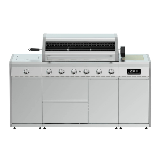
Island 6 Burner Hybrid Barbecue
WARNING! FOR YOUR SAFETY, FOR OUTDOOR USE ONLY
Please read these instructions carefully and ensure that your barbecue is properly installed, assembled,
maintained and serviced in accordance with these instructions.
Failure to follow these instructions may result in serious injury and/or damage to property.
Necessary Tools
Please check the pack contents before attempting to assemble this product. A full checklist of
components is given in this leaflet. If any components are missing, please contact the retailer
from whom you bought this product.
This product takes approximately 180 MINUTES
to assemble with 2 PEOPLE. The fittings pack
contains SMALL ITEMS which should be KEPT
AWAY FROM YOUNG CHILDREN. Read this
leaflet in full before commencing assembly.
GGI66SS
x 44
x 12
x 4
x 2
x 44
x 12
Carbon Monoxide Hazard
Using a barbecue inside can kill you,
it gives off Carbon Monoxide, which has no odour.
Never use a barbecue in enclosed spaces such as
a tent, home/building, vehicle or garage.
x 5
AA Battery (Not included)
Advertisement
Table of Contents

Subscribe to Our Youtube Channel
Related Manuals for Grillstream Island GGI66SS


Summary of Contents for Grillstream Island GGI66SS
- Page 1 Island 6 Burner Hybrid Barbecue GGI66SS x 44 x 44 x 12 x 12 WARNING! FOR YOUR SAFETY, FOR OUTDOOR USE ONLY Please read these instructions carefully and ensure that your barbecue is properly installed, assembled, maintained and serviced in accordance with these instructions. Failure to follow these instructions may result in serious injury and/or damage to property.
-
Page 2: Table Of Contents
GGI66SS Contents Warning Information Page Location of your BBQ Page Connecting to the gas cylinder Page The hose and regulator assembly Page Testing for leaks Page Gas cylinder safety Page What is Propane Page Are all gas bottle gases the same Page How is it different from natural gas Page... -
Page 3: Warning Information
IMPORTANT - BBQS MUST BE INSTALLED IN ACCORDANCE WITH THE MANUFACTURER’S INSTALLATION INSTRUCTIONS, LOCAL GAS FITTING REGULATIONS AND MUNICIPAL BUILDING CODES. GRILLSTREAM BARBECUES, Think carefully when deciding on a location where you are to use your LEISUREGROW PRODUCTS LTD. 0359-23 2575-24 BBQ. -
Page 4: Testing For Leaks
GGI66SS SECURING THE HOSE AND REGULATOR ASSEMBLY GAS CYLINDER SAFETY - Always change over a gas cylinder away from any possible source Quick release connection (Fig. 4) of ignition in a well ventilated area - The BBQ’s manifold connection is a quick release connector - Do not smoke whilst handling gas cylinders - Gently pull back the movable section on the manifold, insert hose - Never store gas cylinder indoors... -
Page 5: Lighting Your Bbq
• off position and wait five minutes for any accumulated gas to clear out of the BBQ before repeating procedure. LIGHTING YOUR BBQ (cont.) Grillstream Grills fit directly on top of each other - do not offset them. lo position is obtained by turning the knob fully anti-clockwise - The... -
Page 6: Hybrid System
You should now turn off the burners DIRECTIONS FOR USE - GAS: completely and close your Barbecue Hood. The beauty of the Grillstream Hybrid System is that there is no additional assembly or conversion process required, whether you want STEP 4: to use it as a Charcoal Barbecue or Gas Barbecue. -
Page 7: Smartgrill Instructions
App, and will be solid after connecting to the App. Wired Probes Plug The Grillstream Smart Grill can handle up to two Battery Gauge separate wired temperature probes to gain superior This displays the current battery level. As the battery control of your grill for perfect results every time. -
Page 8: Time To Grill App Instructions
GGI66SS TIME TO GRILL APP INSTRUCTIONS Bluetooth and App Connection • Search “Time to Grill” in iOS store or Play store to download the App. Alternatively, scan the QR code to the right. • Once App is installed, turn on the Bluetooth function on your device and turn on the Smart Grill Display on the BBQ. •... - Page 9 GGI66SS Step 3: Probe Interface This is the Probe Interface. You can adjust the target temperature of the selected probe (displayed at the top) manually by moving the slider. Alternatively you can set the target temperature by clicking an item in the menu (see next step). Real time probe temperature is displayed in the bottom right corner.
- Page 10 GGI66SS Step 6: Timer Expired Once the set time has elapsed the Timer expired icon will appear. Click OK to return to the App. If the Time to Grill App is not currently displaying on your screen you will still receive a notification if you have allowed the App permission to do so in your phone settings.
- Page 11 GGI66SS TIME TO GRILL APP AT A GLANCE Firebox Real- time Battery capacity Temperature Indicator indicator Meat Probe Real-time Meat Probe Timer Temperature Indicator Meat Probe Target Turn off or Turn on the Temperature Indicator Digitemp Display 1. Firebox Temperature Indicator You can monitor the real-time fire box temperature in Firebox Temperature Indicator.
-
Page 12: Maintenance Of Your Bbq
To clean the Grills effectively use the Grillstream cleaning brush which has been specially designed to quickly and effectively clean your Grillstream Grills. Rinse off with clean water and dry before returning to BBQ. -
Page 13: Troubleshooting
Ignition tube and clear out any debris inside (fig C) WARRANTY All of our Grillstream BBQs and accessories are built to last. Our materials are carefully considered with longevity and safety in mind, the technology used in our products is second to none, and all of this is backed up with our friendly customer care team who are on hand for advice and assistance. -
Page 14: Exploded Diagram A
GGI66SS EXPLODED VIEW Page 14... -
Page 15: Parts List A
Drawer Side Panel - Left Hybrid Flame Tamer Drawer Rear Panel Fat Channel Drawer Runner - Right 195mm Grillstream Grill Drawer Runner - Left 395mm Grillstream Gastro Grill Grease Tray Circular Griddle Plate Grease Cup Bracket Battery Pack Grease Cup Grill Lifter... -
Page 16: Exploded Diagram B
GGI66SS EXPLODED VIEW RIGHT CABINET Page 16... -
Page 17: Parts List B
GGI66SS Description Description Right Cabinet Side Shelf Cabinet Foot Chopping Board Prep Table Leg Ice Bucket / Bin Prep Table Leg Hinge Right Cabinet Rear Panel Door Magnet - Lower Right Cabinet Side Panel - Right Door Magnet - Upper Right Cabinet Side Panel - Left Prep Table Hinge Right Cabinet Base Panel... -
Page 18: Exploded Diagram C
GGI66SS EXPLODED VIEW LEFT CABINET Page 18... -
Page 19: Parts List C
GGI66SS Description Description Ceramic Side Burner Left Cabinet Decorative Panel Ceramic Side Burner Extension Left Cabinet Door Ceramic Side Burner Drip Tray Cabinet Support Bracket Left Cabinet Rear Panel Cabinet Foot Left Cabinet Side Panel - Right Bottle Opener Left Cabinet Side Panel - Left Ceramic Side Burner Grill Left Cabinet Base Panel Page 19... -
Page 20: Fittings List
GGI66SS FITTINGS Part Part Part Part x 44 x 12 x 12 x 44 x 12 x 12 M4x12 Bolt M6x16 Bolt Door Spindle M4x12 SS Bolt Part Part Part Part M6 Washer M4 Washer M4x10 Bolt ST4x12 Bolt Part Part M6x12 Bolt Wing Bolt... - Page 21 GGI66SS STEP 1 Place Right Cabinet Base Panel (7b) upside down on a flat, smooth surface. Unscrew the 8 x Bolts shown. Page 21...
- Page 22 GGI66SS STEP 2 Take 4 x Cabinet Feet (11b) and, using one of the bolts removed in STEP 1, secure in place on the corner shown on each. Page 22...
- Page 23 GGI66SS STEP 3 Further secure Cabinet Feet (11b) in place using 8 x Bolts (A). Part M4x12 Bolt Page 23...
- Page 24 GGI66SS STEP 4 Part unscrew the bolts indicated in Right Cabinet Base Panel (7b), slot the Right Cabinet Side Panels (5b & 6b) into place and retighten bolts. Page 24...
- Page 25 GGI66SS STEP 5 Insert and part tighten 2 x Bolts (B) into Right Cabinet Side Panels (5b & 6b). Slot Right Cabinet Rear Panel (4b) into place and secure to Right Cabinet Base Panel with 2 x Bolts (B). Further secure Right Cabinet Side Panels using 2 x Bolts (B).
- Page 26 GGI66SS STEP 6 Insert Cabinet Support Bar (10b) and secure with 4 x Bolts (A). Part M4x12 Bolt Page 26...
- Page 27 GGI66SS STEP 7 Secure Door Magnet – Lower (14b) to Right Cabinet Base Panel (7b) using 2 x Bolts (D). Part M4x12 SS Bolt Page 27...
- Page 28 GGI66SS STEP 8 Part unscrew the bolts indicated on Right Cabinet Side Shelf (1b) and lower into place on top of assembled Right Cabinet. Slot into place and retighten bolts. Page 28...
- Page 29 GGI66SS STEP 9 Attach Prep Table Leg Hinge (13b) to Prep Table Leg (12b) using 3 x Bolts (D) and 3 x Washers (F). Now open the hinge, ready for the next step. Note: Please take care whenever operating the Prep Table Hinge as there is a risk of trapping fingers.
- Page 30 GGI66SS STEP 10 Attach assembled Prep Table Leg (12b) to rear side of Prep Table (9b) using 3 x Bolts (D). Now attach Door Magnet - Upper (15b) to rear side of Prep Table using 2 x Bolts (D). Attach the Door Stoppers (17b &...
- Page 31 GGI66SS STEP 11 To lower the Prep Table press the button indicated on Prep Table Leg Hinge before collapsing leg and attaching to Door Magnet – Upper. Please do this, ready for the next step. Note: Please take care whenever operating the Prep Table Hinge as there is a risk of trapping fingers. Page 31...
- Page 32 GGI66SS STEP 12 Turn assembled Right Cabinet upside down on a smooth, flat surface and attach the hinges of the Prep Table (12b) to the under side of the Right Island Side Shelf using 4 x Bolts (G). Part M4x10 Bolt Page 32...
- Page 33 GGI66SS STEP 13 Place Left Cabinet Base Panel (7c) upside down on a flat, smooth surface. Unscrew the 8 x Bolts shown. Page 33...
- Page 34 GGI66SS STEP 14 Take 4 x Cabinet Feet (11c) and, using one of each of the bolts removed in STEP 13, secure in place on the corner shown on each. Page 34...
- Page 35 GGI66SS STEP 15 Further secure Cabinet Feet (11c) in place using 8 x Bolts (A). Part M4x12 Bolt Page 35...
- Page 36 GGI66SS STEP 16 Part unscrew the bolts indicated in Left Cabinet Base Panel (7c), slot the Left Cabinet Side Panels (5c & 6c) into place and retighten bolts. Page 36...
- Page 37 GGI66SS STEP 17 Insert and part tighten 2 x Bolts (B) into Left Cabinet Side Panels (5b & 6b). Slot Left Cabinet Rear Panel (4b) into place and secure to Left Cabinet Base Panel with 2 x Bolts (B). Further secure Left Cabinet Side Panels using 2 x Bolts (B).
- Page 38 GGI66SS STEP 18 Insert Cabinet Support Bar (10c) and secure with 4 x Bolts (A). Part M4x12 Bolt Page 38...
- Page 39 GGI66SS STEP 19 Place Ceramic Side Burner (1c) upside down on a flat, smooth surface. Slot both Ceramic Side Burner Extension pieces in place around the drip tray channel and secure together using 2 x Self Tapping Screws (H). Part ST4x12 Bolt Page 39...
- Page 40 GGI66SS STEP 20 Part unscrew the bolts indicated on Ceramic Side Burner (1c) and lower into place on top of assembled Left Cabinet. Slot into place and retighten bolts. Page 40...
- Page 41 GGI66SS STEP 21 Slide Ceramic Side Burner Drip Tray (3c) into place on the assembled Ceramic Side Burner Extension. Page 41...
- Page 42 GGI66SS STEP 22 Install the Bottle Opener (12c) onto control panel of assembled Left Cabinet using 2 x Bolts (D). Unscrew the ignition button and insert 1 x AA battery (not supplied) in place, making note of polarity. Now reattach the ignition button. Part M4x12 SS Bolt Page 42...
- Page 43 GGI66SS STEP 23 Place Cabinet Base Panel (21a) upside down on a flat, smooth surface. Unscrew the 8 x Bolts shown. Page 43...
- Page 44 GGI66SS STEP 24 Take 4 x Cabinet Feet (4a) and, using one of the bolts removed in STEP 23, secure in place on the corner shown on each. Page 44...
- Page 45 GGI66SS STEP 25 Further secure Cabinet Feet (4a) in place using 8 x Bolts (A). Part M4x12 Bolt Page 45...
- Page 46 GGI66SS STEP 26 Part unscrew the bolts indicated from Cabinet Base Panel (21a), slot the Cabinet Side Panels (22a & 23a) into place and retighten bolts. Page 46...
- Page 47 GGI66SS STEP 27 Insert and part tighten 2 x Bolt (B) into Cabinet Side Panels (22a & 23a). Slot Cabinet Rear Panel – Lower (24a) into place and secure to Cabinet Base Panel (21a) with 2 x Bolt (B). Finally, fully tighten bolts into Cabinet Side Panels (22a & 23a). Part M6x16 Bolt Page 47...
- Page 48 GGI66SS STEP 28 Slot Cabinet Rear Panel – Upper (25a) into place and secure to Cabinet Side Panels (22a & 23a) using 2 x Bolts (B). Now secure it to Cabinet Rear Panel – Lower (24a) using 2 x Bolts (A) by screwing upwards through the lower panel.
- Page 49 GGI66SS STEP 29 Attach Cabinet Mid Panel (26a) to Cabinet Base Panel (21a) using 2 x Bolts (B). Now secure into Cabinet Rear Panel – Upper (24a) using 1 x Bolt (A). Part Part M4x12 Bolt M6x16 Bolt Page 49...
- Page 50 GGI66SS STEP 30 Insert Front Support Bar (27a), ensuring magnets are at the bottom edge, and secure into Cabinet Side Panels (22a & 23a) with 4 x Bolts (A). Now secure Cabinet Mid Panel (26a) to Front Support Bar using 1 x Bolt (A). Part M4x12 Bolt Page 50...
- Page 51 GGI66SS STEP 31 Part unscrew bolts indicated from Cabinet Side Panels (22a & 23a) and Front Support Bar (27a). Slot Corner Support Brackets (5a) in place and re-tighten bolts. Page 51...
- Page 52 GGI66SS STEP 32 Attach Drawer Runner - Left (35a) to Cabinet Side Panel – Left from the outside using 4 x Bolts (A). Repeat for the second runner. Part M4x12 Bolt Page 52...
- Page 53 GGI66SS STEP 33 Attach Drawer Runner – Right (34a) to Cabinet Mid Panel (26a) from the outside using 4 x Bolts (A). Repeat for the second runner. Part M4x12 Bolt Page 53...
- Page 54 Unscrew and remove Wingnut and Washer from Thermometer (2a). Thread Thermometer Spindle through Grillstream Logo Plate and then through Glass Window of Hood (1a). Replace Washer and Wingnut. Note: Do not overtighten as this could lead to damaging of the Glass Window.
- Page 55 GGI66SS STEP 35 Secure cooking frame to Cabinet Side Panels (22a & 23a) using 4 x Bolts (B). Part M6x16 Bolt Page 55...
- Page 56 GGI66SS STEP 36 Attach Gas Connection Bracket to Cabinet Side Panel -Right (22a) using 1 x Bolt (A). Now tighten the nut above the Gas Connection Bracket, this will help hold the hose in place when you attach the hose and regulator later. Note: The Gas Connection Bracket and Hose will be attached behind the Control Panel via cable tie, please cut the cable tie carefully to avoid damaging the components behind the Control Panel.
- Page 57 GGI66SS STEP 37 Affix Warming Rack Clip – Right (9a) to inside of Cooking Frame (8a) using 1 x Bolt (B). Repeat for Warming Rack Clip – Left (10a) using 1 x Bolt (B). Part M6x16 Bolt Page 57...
- Page 58 GGI66SS STEP 38 Slot Probe Buffer (7a) over Temperature Probe located inside Cooking Frame (8a) and secure in place using 2 x Bolts (D). Part M4x12 SS Bolt Page 58...
- Page 59 GGI66SS STEP 39 Attach Grease Cup Bracket (37a) to underside of Grease Tray (36a) using 2 x Bolts (A). Place Grease Cup (38a) inside Grease Cup Bracket and then slide underneath Cooking Frame ensuring it is level and on top of runners. Part M4x12 Bolt Page 59...
- Page 60 GGI66SS STEP 40 To connect the Ceramic Side Burner Hose, remove bung and push in the Gas Connector then slide hose inside. Release the Gas Connector and check hose is secure. Please ensure you perform a gas leak check on this connection as instructed on page 62. Finally, connect the two ends of the ignition wire for the Ceramic Side Burner together.
- Page 61 GGI66SS STEP 41 Secure Cooking Frame (8a) to assembled Left Cabinet using 2 x Bolts (B) and 2 x Washers (E). Note: Washers (E) are domed and bottom of dome should be facing the Cooking Frame. Part Part M6x16 Bolt M6 Washer Page 61...
- Page 62 GGI66SS STEP 42 Now secure Cooking Frame (8a) to assembled Right Cabinet using 2 x Bolts (B) and 2 x Washers (E). Note: Washers (E) are domed and bottom of dome should be facing the Cooking Frame. Part Part M6x16 Bolt M6 Washer Page 62...
- Page 63 GGI66SS STEP 43 Further secure Left Cabinet to Cabinet Side Panel – Left (23a) using 4 x Wing Bolts (J), passing them through the cutouts shown and fastening from the other side. Part Wing Bolt Page 63...
- Page 64 GGI66SS STEP 44 Further secure Left Cabinet to Cabinet Side Panel – Right (22a) using 4 x Wing Bolts (J), passing them through the cutouts shown and fastening from the other side. Part Wing Bolt Page 64...
- Page 65 GGI66SS STEP 45 Connect power wire for LED lights and power wire for Smart Grill to the Battery Pack (18a). The reverse of the Battery Pack is magnetic and should attach to Right Cabinet Side Panel - Left (5c) in area shown. Insert 4 x AA Batteries (not supplied) into Battery Pack (18a). The On/Off switch for the LED Control Knob function is located to the left of the control panel.
- Page 66 GGI66SS STEP 46 Insert Door Spindle (C) into left hole of Left Cabinet Base Panel (7c). To fit Left Cabinet Door (9c) in place, first slide the hole on bottom of door over Door Spindle (C), depress springloaded catch on underside of Ceramic Side Burner and position top of door until springloaded catch slides into top hole.
- Page 67 GGI66SS STEP 47 Attach Drawer Rear Panel (33a) to Drawer Base Panel (30a) using 2 x Bolts (D). Attach Drawer Side Panel – Right (31a) to Drawer Base Panel and Drawer Rear Panel using 4 x Bolts (D). Next, attach Drawer Side Panel – Left (32a) to Drawer Base Panel and Drawer Rear Panel using 4 x Bolts (D).
- Page 68 GGI66SS STEP 48 Insert Door Spindle (C) into left hole of Cabinet Base Panel (21a). To fit Cabinet Door (28a) in place, first slide the hole on bottom of door over Door Spindle (C), depress springloaded catch on underside of Cooking Frame and position top of door until springloaded catch slides into top hole.
- Page 69 GGI66SS STEP 49 Insert and part tighten 2 x Bolts (I) into holes indicated on Ceramic Side Burner (1c). Insert the tabs located at the bottom of Left Cabinet Decorative Panel (8c) into the holes indicated on Left Cabinet Base Panel (7c). Tilt top of Left Cabinet Decorative Panel towards Ceramic Side Burner and lift slightly to allow slots in the top to fit over the bolts.
- Page 70 GGI66SS STEP 50 Insert and part tighten 2 x Bolts (I) into holes indicated on Right Cabinet Side Shelf (1b). Insert the tabs located at the bottom of Right Cabinet Decorative Panel (8b) into the holes indicated on Right Cabinet Base Panel (7b). Tilt top of Right Cabinet Decorative Panel towards Right Cabinet Side Shelf and lift slightly to allow slots in the top to fit over the bolts.
- Page 71 GGI66SS STEP 51 Attach 2 x Cabinet Braces (20a) to underside of control panel using 4 x Bolts (D). Part M4x12 SS Bolt Page 71...
- Page 72 GGI66SS STEP 52 Attach 4 x Cabinet Braces (20a) to reverse of Cooking Frame using 8 x Bolts (D). Part M4x12 SS Bolt Page 72...
- Page 73 GGI66SS STEP 53 Hook Grillstream Fat Cup (17b) over holes in Cabinet Side Panel - Right (22a). This should be located directly below the spout of Fat Channel (14a) to catch fat and meat juices channelled from the Grillstream system.
- Page 74 GGI66SS STEP 54 Lift lid of Ceramic Side Burner (1c) and insert Ceramic Side Burner Grill (13c) inside. Lift Hood (1a) and insert Hybrid Flame Tamers (13a) onto locating shelves within the Cooking Frame (8a). Flame Tamers should sit directly above Tube Burners. Place Ice Bucket (3b) and Chopping Board (2b) into opening on the top of the Right Cabinet Side Shelf.
- Page 75 GGI66SS STEP 55 Insert Fat Channel (14a) into Cooking Frame by first sliding the thin end (spout) through righthand side of Cooking Frame and then slotting the front lip of the Fat Channel between and Cooking Frame and Control Panel. Page 75...
- Page 76 Cooking Frame. Top Grills should sit directly on top of the bottom Grill. The Circular Griddle Plate should rest on top of the upper Grillstream Gastro Grill above the cutout section. You can also swap out the Circular Griddle Plate for a variety of Grillstream Gastro Accessories including a Pizza Stone, Wok or Chicken Roaster (sold separately) for a varied cooking experience.
- Page 77 GGI66SS STEP 57 Insert back legs of Warming Rack (12a) into channel on Warming Rack Clips (9a & 10a). Angle Warming Rack forwards and insert front legs into holes located on Cooking Frame (8a). To operate, lift front legs out of holes in Cooking Frame and tilt Warming Rack upwards. Pull Warming Rack forwards slightly so back legs are inline with vertical track and slide downwards.
-
Page 78: Leak Test
GGI66SS TESTING YOUR BBQ TESTING FOR LEAKS - DO THIS BEFORE USING YOUR BBQ. Note - Do not test for gas leaks with an open flame. If you smell gas, turn off at the source. Before first use, at the beginning of each new season, or whenever a gas cylinder is changed, you must check for gas leaks. - Page 79 PLEASE KEEP THESE INSTRUCTIONS FOR FUTURE REFERENCE Grillstream Barbecues Part of the LeisureGrow Group Dewmead Farm, New Inn Road, Hinxworth, Hertfordshire SG7 5HG, United Kingdom. Tel: +44 (0)1462 744500 E-mail:consumer@leisuregrow.com...
Need help?
Do you have a question about the Island GGI66SS and is the answer not in the manual?
Questions and answers