Table of Contents
Advertisement
Quick Links
Maintenance Manual
TM
VectorStar
ME7848A/E Series
Opto-electronic Network Analyzer
VNA, O/E Calibration Module, and E/O Converter:
ME7848A/E-0210, 110 GHz, 1550 nm system
ME7848A/E-0211, 110 GHz, 1310 nm system
ME7848A-0240 40 GHz, 850 nm system
ME7848A-0270 70 GHz, 1550 nm system
ME7848A-0271 70 GHz, 1310 nm system
ME7848A-0272 70 GHz, 1310/1550 nm system
VNA and O/E module only:
ME7848A/E-0110 110 GHz, 1550 nm system
ME7848A/E-0111 110 GHz, 1310 nm system
ME7848A/E-0112 110 GHz, 1310/1550 nm system
ME7848A-0140 40 GHz, 850 nm system
ME7848A-0170 70 GHz, 1550 nm system
ME7848A-0171 70 GHz, 1310 nm system
ME7848A-0172 70 GHz, 1310/1550 nm system
Anritsu Company
P/N: 10410-00778
490 Jarvis Drive
Revision C
Morgan Hill, CA 95037-2809
Published: October 2023
USA
Copyright 2023 Anritsu Company. All Rights Reserved.
http://www.anritsu.com
Advertisement
Table of Contents
Troubleshooting

Related Manuals for Anritsu VectorStar ME7848E Series


Summary of Contents for Anritsu VectorStar ME7848E Series
- Page 1 ME7848A-0170 70 GHz, 1550 nm system ME7848A-0171 70 GHz, 1310 nm system ME7848A-0172 70 GHz, 1310/1550 nm system Anritsu Company P/N: 10410-00778 490 Jarvis Drive Revision C Morgan Hill, CA 95037-2809 Published: October 2023 Copyright 2023 Anritsu Company. All Rights Reserved. http://www.anritsu.com...
- Page 2 NOTICE Anritsu Company has prepared this manual for use by Anritsu Company personnel and customers as a guide for the proper installation, operation and maintenance of Anritsu Company equipment and computer programs. The drawings, specifications, and information contained herein are the property of Anritsu Company, and any unauthorized use or disclosure of these drawings, specifications, and information is prohibited;...
-
Page 3: Table Of Contents
Contacting Anritsu ........ - Page 4 Table of Contents (Continued) ME7848A/E-0211 System Verification – 1310 nm Configuration ..... . 3-19 ME7848A/E-0271 1310 nm System Setup ........3-19 Optical Power Meter (OPM) Measurement Setup –...
- Page 5 Table of Contents (Continued) Chapter 5 — Troubleshooting Introduction ..............5-1 General Safety Warnings .
- Page 6 Contents-4 PN: 10410-00778 Rev. C VectorStar ME7848A/E Series MM...
-
Page 7: Chapter 1 - General Information
Opto-electronic Network Analyzer. Identification Number All Anritsu instruments are assigned a unique identification number (up to seven-digit), such as “090201” or “1010222”. This number appears on a decal affixed to the rear panel of each instrument. Use the VectorStar VNA’s identification number during any correspondence with Anritsu Customer Service about Anritsu instruments. -
Page 8: Contacting Anritsu
From here, you can select the latest sales, service and support contact information in your country or region, provide online feedback, complete a “Talk to Anritsu” form to get your questions answered, or obtain other services offered by Anritsu. -
Page 9: Vectorstar Mn4775A E/O Converter
VectorStar MN4765B O/E Calibration Module • MN4765B O/E Calibration Module Operating Manual – 10410-00742 Updates to Manuals For updates to any of the VectorStar Series VNA documentation, visit Anritsu’s Web site at: http://www.anritsu.com/en-us/test-measurement/products/ms4640b-series Electrostatic Discharge (ESD) Prevention All electronic devices, components, and instruments can be damaged by electrostatic discharge. It is important to take preventative measures to protect the instrument and its internal subassemblies from electrostatic discharge. - Page 10 1-6 ME7848A/E Series ONA System Overview General Information Table 1-1. ME7848A/E-02xx Standard ONA System Components (2 of 5) Part Number Name Specifications Standard ME7848E-0210 Configuration ME7838EX VectorStar ME7838EX Broadband Vector 10 MHz to 110 GHz W(m) Test Ports Network Analyzer (VNA) MN4765B with O/E Calibration Module option 0110...
- Page 11 General Information 1-6 ME7848A/E Series ONA System Overview Table 1-1. ME7848A/E-02xx Standard ONA System Components (3 of 5) Part Number Name Specifications MS4644B VNA Front Panel Options – Select One (1) MS4644B-051 Front Panel Loops 6 Front Panel Loops Provides front panel loops for b1, a1, Port 1 Source, Port 2 Source, a2, and b2 MS4644B-061 Active Measurement Suite...
- Page 12 1-6 ME7848A/E Series ONA System Overview General Information Table 1-1. ME7848A/E-02xx Standard ONA System Components (4 of 5) Part Number Name Specifications Standard ME7848A-0271 Configuration MS4647B VectorStar MS4647B Vector Network Analyzer 10 MHz to 70 GHz V(m) Test Ports (VNA) MN4765B with O/E Calibration Module option 0071...
- Page 13 General Information 1-6 ME7848A/E Series ONA System Overview Table 1-1. ME7848A/E-02xx Standard ONA System Components (5 of 5) Part Number Name Specifications MS4647B VNA Front Panel Options – Select One (1) MS4647B-051 Front Panel Loops 6 Front Panel Loops • Provides front panel loops for b1, a1, Port 1 Source, Port 2 Source, a2, and MS4647B-061...
-
Page 14: Me7848A/E-01Xx Standard Broadband Vna System Components
1-6 ME7848A/E Series ONA System Overview General Information ME7848A/E-01xx Standard Broadband VNA System Components (VNA and O/E module only) Table 1-2. ME7848A/E-01xx Standard ONA System Components (1 of 4) Part Number Name Specifications Standard ME7848A-0110 Configuration ME7838AX VectorStar ME7838AX Broadband Vector 10 MHz to 125 GHz;... - Page 15 General Information 1-6 ME7848A/E Series ONA System Overview Table 1-2. ME7848A/E-01xx Standard ONA System Components (2 of 4) Part Number Name Specifications Standard ME7848E-0112 Configuration ME7838EX VectorStar ME7838EX Broadband Vector 10 MHz to 110 GHz; W(m) Test Ports Network Analyzer (VNA) MN4765B with O/E Calibration Module option 0112...
- Page 16 1-6 ME7848A/E Series ONA System Overview General Information Table 1-2. ME7848A/E-01xx Standard ONA System Components (3 of 4) Part Number Name Specifications MS4647B VNA Front Panel Options – Select One (1) MS4647B-051 Front Panel Loops 6 Front Panel Loops • Provides front panel loops for b1, a1, Port 1 Source, Port 2 Source, a2, and b2 MS4647B-061...
-
Page 17: Recommended Test Equipment
General Information 1-7 Recommended Test Equipment Table 1-2. ME7848A/E-01xx Standard ONA System Components (4 of 4) Part Number Name Specifications MS4647B VNA Front Panel Options – Select One (1) MS4647B-051 Front Panel Loops 6 Front Panel Loops • Provides front panel loops for b1, a1, Port 1 Source, Port 2 Source, a2, and b2 MS4647B-061 Active Measurement Suite... - Page 18 1-7 Recommended Test Equipment General Information 1-12 PN: 10410-00778 Rev. C VectorStar ME7848A/E Series MM...
-
Page 19: Chapter 2 - Replaceable Parts
Table 2-1. There are no serviceable components or subassemblies inside the MN4775A converters or the Note MN4765B O/E modules. The modules must be returned to Anritsu Company for repair. Table 2-1. ME7848A/E Series System Level Replaceable Parts List Part Number... - Page 20 2-2 ME7848A/E Series System Replaceable Parts Replaceable Parts PN: 10410-00778 Rev. C VectorStar ME7848A/E Series MM...
-
Page 21: Chapter 3 - Performance Verification
Chapter 3 — Performance Verification Introduction This chapter provides the following procedures to be used to verify the performance of the ME7848A/E Opto-electronic Network Analyzer systems.: • Section 3-4 “ME7848A/E-0210 System Verification – 1550 nm Configuration” on page 3-3 • Section 3-5 “ME7848A/E-0211 System Verification –... -
Page 22: Laser Safety
If equipment is used in a manner not specified by the manufacturer, the protection provided by the equipment may be impaired. Only with written consent from Anritsu may changes to single components be carried out or components not supplied by Anritsu be used. -
Page 23: Me7848A/E-0210 System Verification - 1550 Nm Configuration
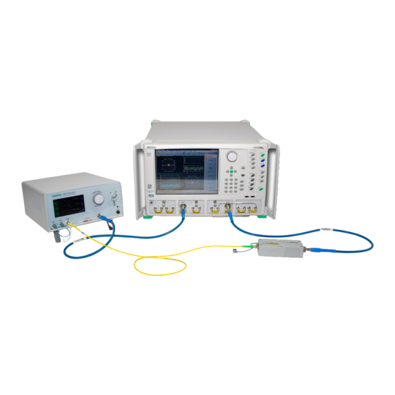
Safety Cap in Place! Figure 3-1. Initial ME7848A/E-0210 1550 nm Initial System Setup Refer to the MN4775A Operation Manual – 10410-00774 regarding proper operation of the Anritsu Note E/O Converter. 2. Apply power to MN4775A-0110 E/O Converter by pushing the Standby button until it turns green. - Page 24 3-4 ME7848A/E-0210 System Verification – 1550 nm Configuration Performance Verification 4. Apply power to MN4765B-0110 O/E Calibration Module via +12 V power cube. 5. MN4775A-0110 E/O Converter: a. Verify Optical Loop is in place on MN4775A-0110 E/O Converter. There is a key on the optical fiber cable that needs to be oriented correctly before the screw will Note tighten correctly.
-
Page 25: Optical Power Meter (Opm) Measurement Setup - 1550 Nm Configuration
Performance Verification 3-4 ME7848A/E-0210 System Verification – 1550 nm Configuration 10. Select ITU Channel: a. Touch center section of LASER WAVELENGTH region to bring up secondary screen (not shown in figure 3-2). b. At secondary screen select ITU Channel 39 = 1550.12 nm WAVE LENGTH. Touch green checkmark. c. -
Page 26: Optical Power Meter Measurement - 1550 Nm Configuration
3-4 ME7848A/E-0210 System Verification – 1550 nm Configuration Performance Verification Optical Power Meter Measurement – 1550 nm Configuration Anritsu MN4775A-0110 Ignition Key “ON” Laser Out/In Optical Loop Connected ThorLabs PM100D + S155C 800-1700 nm Sensor -65.67 dBm λ Lambda Key... -
Page 27: Frequency Response Repeatability S21 Setup - 1550 Nm Configuration
4. Connect Green-colored end of Optical cable to MN4765B-0110 as shown in Figure 3-5. 5. Connect the VNA Port 1 to Anritsu MN4775A-0110 E/O Converter RF Input as shown in Figure 3-5. • Use torque wrench to tighten the connectors to ensure that the connections do not work themselves loose during the test. -
Page 28: Frequency Response Repeatability S21-Mag Measurement - 1550 Nm Configuration
3-4 ME7848A/E-0210 System Verification – 1550 nm Configuration Performance Verification 10. Select ITU-Channel: a. Touch center section of LASER WAVELENGTH region to bring up secondary screen. b. At Secondary Screen select ITU Channel 39 = 1550.041 nm WAVE LENGTH. c. Touch Home to return to the main screen. 11. - Page 29 Performance Verification 3-4 ME7848A/E-0210 System Verification – 1550 nm Configuration 2. Configure the VectorStar VNA; using Frequency Based Segmented Sweep, create a segmented sweep table as shown in Figure 3-6. a. Select Channel, then select Sweep. b. Select Freq-based Seg. Sweep Setup and a new window appears at the bottom of the screen. c.
- Page 30 3-4 ME7848A/E-0210 System Verification – 1550 nm Configuration Performance Verification 9. There are many ways one can set up Microsoft Excel for calculating the RMS values. Here is an example: a. Assume the data are in an Excel worksheet as follows: i.
-
Page 31: Optical Noise Floor S21 Setup - 1550 Nm Configuration
4. Connect Green-colored end of Optical cable to MN4765B-0110 as shown in Figure 3-7. 5. Connect the VNA Port 1 to Anritsu MN4775A-0110 E/O Converter RF Input as shown in Figure 3-7. • Use torque wrench to tighten the connectors to ensure that the connections do not work themselves loose during the test. - Page 32 3-4 ME7848A/E-0210 System Verification – 1550 nm Configuration Performance Verification 10. Select ITU-Channel a. Touch center section of LASER WAVELENGTH region to bring up secondary screen. b. At secondary screen select ITU Channel 39 = 1550.041 nm WAVE LENGTH. c. Touch Home to return to the main screen. 11.
-
Page 33: Optical Nose Floor S21 Measurement - 1550 Nm Configuration
Performance Verification 3-4 ME7848A/E-0210 System Verification – 1550 nm Configuration 15. Configure the VectorStar VNA: using Frequency Based Segmented Sweep, create a segmented sweep table as shown in Figure 3-8. a. Select Channel, then select Sweep. b. Select Freq-based Seg. Sweep Setup and a new window appears at the bottom of the screen. c. - Page 34 3-4 ME7848A/E-0210 System Verification – 1550 nm Configuration Performance Verification 6. Select Edit Cal Params (see Figure 3-9). Figure 3-9. TRANSMISSION FREQUENCY RESPONSE CAL SETUP (SOLT/R, Coaxial) Dialog 3-14 PN: 10410-00778 Rev. C VectorStar ME7848A/E Series MM...
- Page 35 Performance Verification 3-4 ME7848A/E-0210 System Verification – 1550 nm Configuration 7. Click on Thru1-2 Info and the screen appears (see Figure 3-10) and verify Length (mm), Line loss (dB/mm), and @Frequency (GHz) are set to 0.000. Figure 3-10. THRU INFO Dialog 8.
- Page 36 Port 1 Port 2 Anritsu 3739C FF M Anritsu Anritsu Anritsu 1 mm cable 3743xX 3743xX MN4765B-0110 Anritsu MN4775A-0110 Ignition Key “OFF” Laser Out/In Optical Loop Connected Figure 3-11. Turning Off Laser 3-16 PN: 10410-00778 Rev. C VectorStar ME7848A/E Series MM...
- Page 37 Performance Verification 3-4 ME7848A/E-0210 System Verification – 1550 nm Configuration 12. Select Scale a. Click on Reference Position and set it to 10. The screen should look like Figure 3-12 (the frequency list used in the plot is different from that set up in this procedure, but the overall shape of the curve should be similar).
- Page 38 3-4 ME7848A/E-0210 System Verification – 1550 nm Configuration Performance Verification 18. There are many ways one can set up Microsoft Excel for calculating the RMS values. Here is an example: a. Assume the data are in an Excel worksheet as follows: i.
-
Page 39: Me7848A/E-0211 System Verification - 1310 Nm Configuration
Loop Connected Safety Cap in Place! Figure 3-13. Initial ME7848A/E-0271 1310 nm Initial System Setup Refer to the MN4775A Operation Manual – 10410-00774 regarding proper operation of the Anritsu Note E/O Converter. VectorStar ME7848A/E Series MM PN: 10410-00778 Rev. C... - Page 40 3-5 ME7848A/E-0211 System Verification – 1310 nm Configuration Performance Verification 2. Apply power to MN4775A-0111 E/O Converter by pushing the Standby button until it turns green. 3. Apply power to the VNA. 4. Apply power to MN4765B-0111 O/E Calibration Module via +12 V power cube. 5.
-
Page 41: Optical Power Meter (Opm) Measurement Setup - 1310 Nm Configuration
Performance Verification 3-5 ME7848A/E-0211 System Verification – 1310 nm Configuration 10. Select ITU-Channel. • Not required for 1310 System as wavelength is fixed. 11. Select VOA Mode. a. Touch center section of VOA OUTPUT POWER region to bring up secondary screen as shown in Figure 3-14 (left side). -
Page 42: Optical Power Meter Measurement - 1310 Nm Configuration
3-5 ME7848A/E-0211 System Verification – 1310 nm Configuration Performance Verification Optical Power Meter Measurement – 1310 nm Configuration Anritsu MN4775A-0111 Ignition Key “ON” Laser Out/In Optical Loop Connected ThorLabs PM100D + S155C 800-1700 nm Sensor -65.67 dBm λ Lambda Key... -
Page 43: Frequency Response Repeatability S21 Setup - 1310 Nm Configuration
4. Connect Green-colored end of Optical cable to MN4765B-0111 as shown in Figure 3-17. 5. Connect the VNA Port 1 to Anritsu MN4775A-0111 E/O Converter RF Input as shown in Figure 3-17. • Use torque wrench to tighten the connectors to ensure that the connections do not work themselves loose during the test. -
Page 44: Frequency Response Repeatability S21-Mag Measurement - 1310 Nm Configuration
3-5 ME7848A/E-0211 System Verification – 1310 nm Configuration Performance Verification 9. Make settings on MN4775A-0111 via the display touch screen as described below. a. Touch LASER ON square-pad to turn the LASER to ON state. b. Touch VOA ON square-pad to enable VOA Attenuator. c. - Page 45 Performance Verification 3-5 ME7848A/E-0211 System Verification – 1310 nm Configuration 2. Configure the VectorStar VNA; using Frequency Based Segmented Sweep, create a segmented sweep table as shown in Figure 3-18. a. Select Channel, then select Sweep. b. Select Freq-based Seg. Sweep Setup and a new window appears at the bottom of the screen. c.
- Page 46 3-5 ME7848A/E-0211 System Verification – 1310 nm Configuration Performance Verification 9. There are many ways one can set up Microsoft Excel for calculating the RMS values. Below is an example: a. Assume the data are in an Excel worksheet as follows: i.
-
Page 47: Optical Noise Floor S21 Setup - 1310 Nm Configuration
4. Connect Green-colored end of Optical cable to MN4765B-0111 as shown in Figure 3-19. 5. Connect the VNA Port 1 to Anritsu MN4775A-0111 E/O Converter RF Input as shown in Figure 3-19. • Use torque wrench to tighten the connectors to ensure that the connections do not work themselves loose during the test. - Page 48 3-5 ME7848A/E-0211 System Verification – 1310 nm Configuration Performance Verification 10. Select ITU-Channel a. Channel setting not required on 1310 nm systems 11. Select VOA Mode: a. Touch center section of VOA OUTPUT POWER region to bring up secondary screen. b.
- Page 49 Performance Verification 3-5 ME7848A/E-0211 System Verification – 1310 nm Configuration 15. Configure the VectorStar VNA; using Frequency Based Segmented Sweep, create a segmented sweep table as shown in Figure 3-20. a. Select Channel, then select Sweep. b. Select Freq-based Seg. Sweep Setup and a new window appears at the bottom of the screen. c.
-
Page 50: Optical Nose Floor S21 Measurement - 1310 Nm Configuration
3-5 ME7848A/E-0211 System Verification – 1310 nm Configuration Performance Verification Optical Nose Floor S21 Measurement – 1310 nm Configuration 1. On VectorStar VNA, select Calibration. 2. Select Calibrate. 3. Select Manual Cal. 4. Select Transmission Freq. Response. 5. Select Modify Cal Setup. 6. - Page 51 Performance Verification 3-5 ME7848A/E-0211 System Verification – 1310 nm Configuration 7. Click on Thru1-2 Info and the THRU INFO dialog appears (see Figure 3-22) and verify that Length (mm), Line loss (dB/mm), and @Frequency (GHz) are set to 0.000. Figure 3-22. THRU INFO Dialog 8.
- Page 52 Port 1 Port 2 Anritsu 3739C FF M Anritsu Anritsu Anritsu 1 mm cable 3743xX 3743xX MN4765B-0111 Anritsu MN4775A-0111 Ignition Key “OFF” Laser Out/In Optical Loop Connected Figure 3-23. Turning Off Laser 3-32 PN: 10410-00778 Rev. C VectorStar ME7848A/E Series MM...
- Page 53 Performance Verification 3-5 ME7848A/E-0211 System Verification – 1310 nm Configuration 12. Select Scale a. Click on Reference Position and set it to 10. The screen should look like Figure 3-24. The frequency list used in this plot is different from that set up in this procedure but the overall shape of the curve should be similar.
- Page 54 3-5 ME7848A/E-0211 System Verification – 1310 nm Configuration Performance Verification 18. There are many ways one can set up Microsoft Excel for calculating the RMS values. Here is an example: a. Assume the data are in an Excel worksheet as follows: i.
-
Page 55: Me7848A-0240 System Verification - 850 Nm Configuration
ME7848A-0240 850 nm System Setup 1. Configure components (VNA, O/E, E/O, RF, and Optical cables) as shown in Figure 3-25. The Anritsu MN4775A-0040 does not have Laser Out and Laser In connectors like the Note MN4775A-0070, MN4775A-0071, and MN4775A-0072. Anritsu MN4775A-0040 Ignition Key “OFF”... - Page 56 3-6 ME7848A-0240 System Verification – 850 nm Configuration Performance Verification 5. MN4775A-0040 E/O Converter: g. Keep Ignition-Key in OFF Position, as shown in Figure 3-25. 6. Make initial VNA RF Connections shown in Figure 3-25. a. Place KF-KF Adapter on VNA Port 2. b.
-
Page 57: Optical Power Meter (Opm) Measurement Setup - 850 Nm Configuration
Performance Verification 3-6 ME7848A-0240 System Verification – 850 nm Configuration 11. Select VOA Mode: a. Touch center section of VOA OUTPUT POWER region to bring up secondary screen as shown in Figure 3-26 (left side). b. At secondary screen, touch Mode and then touch Out to change mode to CONSTANT OUTPUT. c. -
Page 58: Optical Power Meter Measurement - 850 Nm Configuration
3-6 ME7848A-0240 System Verification – 850 nm Configuration Performance Verification Optical Power Meter Measurement – 850 nm Configuration Anritsu MN4775A-0040 Ignition Key “ON” Laser Aperture No optical loop in this Configuration ThorLabs PM100D + S155C 800-1700 nm Sensor -65.67 dBm λ... -
Page 59: Frequency Response Repeatability S21 Setup - 850 Nm Configuration
4. Connect Green-colored end of Optical cable to MN4765B-0040 as shown in Figure 3-29. 5. Connect the VNA Port 1 to Anritsu MN4775A-0040 E/O Converter RF Input as shown in Figure 3-29. • Use torque wrench to tighten the connectors to ensure that the connections do not work themselves loose during the test. -
Page 60: Frequency Response Repeatability S21-Mag Measurement - 850 Nm Configuration
3-6 ME7848A-0240 System Verification – 850 nm Configuration Performance Verification 10. Select VOA Mode a. Touch center section of VOA OUTPUT POWER region to bring up secondary screen. b. At secondary screen, touch Mode and then touch Out to change mode to CONSTANT OUTPUT. c. - Page 61 Performance Verification 3-6 ME7848A-0240 System Verification – 850 nm Configuration 3. Normalize the trace (data divided by memory). a. Select Display. b. Select View Trace. c. Select Store Data to Memory. d. Select Data, Memory Math. 4. Select Sweep and then Hold functions. Select Single Sweep & Hold. 5.
-
Page 62: Optical Noise Floor S21 Setup - 850 Nm Configuration
4. Connect Green-colored end of optical cable to MN4765B-0040 as shown in Figure 3-31. 5. Connect the VNA Port 1 to Anritsu MN4775A-0040 E/O Converter RF Input as shown in Figure 3-31. • Use torque wrench to tighten the connectors to ensure that the connections do not work themselves loose during the test. - Page 63 Performance Verification 3-6 ME7848A-0240 System Verification – 850 nm Configuration 10. Select VOA Mode: a. Touch center section of VOA OUTPUT POWER region to bring up secondary screen. b. At secondary screen, touch Mode and then touch Out to change mode to CONSTANT OUTPUT. c.
-
Page 64: Optical Nose Floor S21 Measurement - 850 Nm Configuration
3-6 ME7848A-0240 System Verification – 850 nm Configuration Performance Verification Optical Nose Floor S21 Measurement – 850 nm Configuration 1. On VectorStar VNA, select Calibration. 2. Select Calibrate. 3. Select Manual Cal. 4. Select Transmission Freq. Response. 5. Select Modify Cal Setup. 6. - Page 65 Performance Verification 3-6 ME7848A-0240 System Verification – 850 nm Configuration 7. Click on Thru1-2 Info and the THRU INFO dialog appears (see Figure 3-34) and verify that Length (mm), Line loss (dB/mm), and @Frequency (GHz) are set to 0.000. Figure 3-34. THRU INFO Dialog 8.
- Page 66 3-6 ME7848A-0240 System Verification – 850 nm Configuration Performance Verification 11. Set E/O Converter Ignition key to OFF (see figure Figure 3-35). Anritsu MN4775A-0040 Ignition Key “OFF” Laser Aperture VectorStar Port 1 Port 2 Anritsu MN4765B-0040 Figure 3-35. Turning Off Laser 12.
- Page 67 Performance Verification 3-6 ME7848A-0240 System Verification – 850 nm Configuration 18. There are many ways one can set up Microsoft Excel for calculating the RMS values. Here is an example: a. Assume the data are in an Excel worksheet as follows: i.
-
Page 68: Me7848A-0270 System Verification - 1550 Nm Configuration
Anritsu MN4765B-0070 Figure 3-36. Initial ME7848A-0270 1550 nm Initial System Setup Refer to the MN4775A Operation Manual – 10410-00774 regarding proper operation of the Anritsu Note E/O Converter. 2. Apply power to MN4775A-0070 E/O Converter by pushing the Standby button until it turns green. - Page 69 Performance Verification 3-7 ME7848A-0270 System Verification – 1550 nm Configuration 5. MN4775A-0070 E/O Converter: a. Verify Optical Loop is in place on MN4775A-0070 E/O Converter. There is a key on the optical fiber cable that needs to be oriented correctly before the screw will Note tighten correctly.
-
Page 70: Optical Power Meter (Opm) Measurement Setup - 1550 Nm Configuration
3-7 ME7848A-0270 System Verification – 1550 nm Configuration Performance Verification 10. Select ITU Channel: a. Touch center section of LASER WAVELENGTH region to bring up secondary screen (not shown in figure 3-2). b. At secondary screen select ITU Channel 34 = 1550.12 nm WAVE LENGTH. Touch green checkmark. c. -
Page 71: Optical Power Meter Measurement - 1550 Nm Configuration
Navigate to 1550nm Wavelength icon in menu bar area. c. On PM100D Meter select OK to choose 1550 nm selection, as shown in Figure 3-38. Optical Power Meter Measurement – 1550 nm Configuration Anritsu MN4775A-0070 Ignition Key “ON” Laser Out/In Optical Loop... -
Page 72: Frequency Response Repeatability S21 Setup - 1550 Nm Configuration
4. Connect Green-colored end of Optical cable to MN4765B-0070 as shown in Figure 3-40. 5. Connect the VNA Port 1 to Anritsu MN4775A-0070 E/O Converter RF Input as shown in Figure 3-40. • Use torque wrench to tighten the connectors to ensure that the connections do not work themselves loose during the test. -
Page 73: Frequency Response Repeatability S21-Mag Measurement - 1550 Nm Configuration
Performance Verification 3-7 ME7848A-0270 System Verification – 1550 nm Configuration 9. Make settings on MN4775A-0070 via the display touch screen as below. a. Touch LASER ON square-pad to turn the LASER to ON state. b. Touch VOA ON square-pad to enable VOA Attenuator. c. - Page 74 3-7 ME7848A-0270 System Verification – 1550 nm Configuration Performance Verification 2. Configure the VectorStar VNA; using Frequency Based Segmented Sweep, create a segmented sweep table as shown in Figure 3-41. a. Select Channel, then select Sweep. b. Select Freq-based Seg. Sweep Setup and a new window appears at the bottom of the screen. c.
-
Page 75: Optical Noise Floor S21 Setup - 1550 Nm Configuration
Optical Noise Floor S21 Setup – 1550 nm Configuration 1. Power on MN4775A-0070, MS464xB, and MN4765B and allow the instruments to warm up for 90 minutes. 2. Verify MN4775A-0070 E/O Converter Ignition key is set to OFF. Anritsu MN4775A-0070 Ignition Key “OFF” Laser Out/In Optical... - Page 76 4. Connect Green-colored end of Optical cable to MN4765B-0070 as shown in Figure 3-42. 5. Connect the VNA Port 1 to Anritsu MN4775A-0070 E/O Converter RF Input as shown in Figure 3-42. • Use torque wrench to tighten the connectors to ensure that the connections do not work themselves loose during the test.
-
Page 77: Optical Nose Floor S21 Measurement - 1550 Nm Configuration
Performance Verification 3-7 ME7848A-0270 System Verification – 1550 nm Configuration 16. Configure the VectorStar VNA: using Frequency Based Segmented Sweep, create a segmented sweep table as shown in Figure 3-43. a. Select Channel, then select Sweep. b. Select Freq-based Seg. Sweep Setup and a new window appears at the bottom of the screen. c. - Page 78 3-7 ME7848A-0270 System Verification – 1550 nm Configuration Performance Verification 6. Select Edit Cal Params (see Figure 3-44). Figure 3-44. TRANSMISSION FREQUENCY RESPONSE CAL SETUP (SOLT/R, Coaxial) Dialog 3-58 PN: 10410-00778 Rev. C VectorStar ME7848A/E Series MM...
- Page 79 Performance Verification 3-7 ME7848A-0270 System Verification – 1550 nm Configuration 7. Click on Thru1-2 Info and the screen appears (see Figure 3-45) and verify Length (mm), Line loss (dB/mm), and @Frequency (GHz) are set to 0.000. Figure 3-45. THRU INFO Dialog 8.
- Page 80 3-7 ME7848A-0270 System Verification – 1550 nm Configuration Performance Verification 11. Set E/O Converter Ignition key to OFF, see figure Figure 3-46. Anritsu MN4775A-0070 Ignition Key “OFF” Laser Out/In Optical Loop Connected VectorStar Port 1 Port 2 Anritsu MN4765B-0070 Figure 3-46. Turning Off Laser 3-60 PN: 10410-00778 Rev.
- Page 81 Performance Verification 3-7 ME7848A-0270 System Verification – 1550 nm Configuration 12. Select Scale a. Click on Reference Value and set it to -50 dB. The screen should look like Figure 3-47. Figure 3-47. Typical Noise Floor Display—Reference Only 13. Select Sweep and then Hold Functions. Select Single Sweep & Hold. 14.
- Page 82 3-7 ME7848A-0270 System Verification – 1550 nm Configuration Performance Verification 18. There are many ways one can set up Microsoft Excel for calculating the RMS values. Here is an example: a. Assume the data are in an Excel worksheet as follows: i.
-
Page 83: Me7848A-0271 System Verification - 1310 Nm Configuration
Anritsu MN4765B-0071 Figure 3-48. Initial ME7848A-0271 1310 nm Initial System Setup Refer to the MN4775A Operation Manual – 10410-00774 regarding proper operation of the Anritsu Note E/O Converter. 2. Apply power to MN4775A-0071 E/O Converter by pushing the Standby button until it turns green. - Page 84 3-8 ME7848A-0271 System Verification – 1310 nm Configuration Performance Verification 5. MN4775A-0071 E/O Converter: a. Verify Optical Loop is in place on MN4775A-0071 E/O Converter. There is a key on the optical fiber cable that needs to be oriented correctly before the screw will Note tighten correctly.
-
Page 85: Optical Power Meter (Opm) Measurement Setup - 1310 Nm Configuration
Performance Verification 3-8 ME7848A-0271 System Verification – 1310 nm Configuration 11. Select VOA Mode. a. Touch center section of VOA OUTPUT POWER region to bring up secondary screen as shown in Figure 3-49 (left side). b. At secondary screen, touch Mode and then touch Out to change mode to CONSTANT OUTPUT. c. -
Page 86: Optical Power Meter Measurement - 1310 Nm Configuration
3-8 ME7848A-0271 System Verification – 1310 nm Configuration Performance Verification Optical Power Meter Measurement – 1310 nm Configuration Anritsu MN4775A-0071 Ignition Key “ON” Laser Out/In Optical Loop Connected ThorLabs PM100D + S155C 800-1700 nm Sensor -65.67 dBm λ Lambda Key... -
Page 87: Frequency Response Repeatability S21 Setup - 1310 Nm Configuration
4. Connect Green-colored end of Optical cable to MN4765B-0071 as shown in Figure 3-52. 5. Connect the VNA Port 1 to Anritsu MN4775A-0071 E/O Converter RF Input as shown in Figure 3-52. • Use torque wrench to tighten the connectors to ensure that the connections do not work themselves loose during the test. -
Page 88: Frequency Response Repeatability S21-Mag Measurement - 1310 Nm Configuration
3-8 ME7848A-0271 System Verification – 1310 nm Configuration Performance Verification 11. Select VOA Mode a. Touch center section of VOA OUTPUT POWER region to bring up secondary screen. b. At secondary screen, touch Mode and then touch Out to change mode to CONSTANT OUTPUT. c. - Page 89 Performance Verification 3-8 ME7848A-0271 System Verification – 1310 nm Configuration 3. Normalize the trace (data divided by memory): a. Select Display. b. Select View Trace. c. Select Store Data to Memory. d. Select Data, Memory Math. 4. Select Sweep and then Hold Functions. Select Single Sweep & Hold. 5.
-
Page 90: Optical Noise Floor S21 Setup - 1310 Nm Configuration
4. Connect Green-colored end of Optical cable to MN4765B-0071 as shown in Figure 3-54. 5. Connect the VNA Port 1 to Anritsu MN4775A-0071 E/O Converter RF Input as shown in Figure 3-54. • Use torque wrench to tighten the connectors to ensure that the connections do not work themselves loose during the test. - Page 91 Performance Verification 3-8 ME7848A-0271 System Verification – 1310 nm Configuration 11. Select VOA Mode: a. Touch center section of VOA OUTPUT POWER region to bring up secondary screen. b. At secondary screen, touch Mode and then touch Out to change mode to CONSTANT OUTPUT. c.
-
Page 92: Optical Nose Floor S21 Measurement - 1310 Nm Configuration
3-8 ME7848A-0271 System Verification – 1310 nm Configuration Performance Verification Optical Nose Floor S21 Measurement – 1310 nm Configuration 1. On VectorStar VNA, select Calibration. 2. Select Calibrate. 3. Select Manual Cal. 4. Select Transmission Freq. Response. 5. Select Modify Cal Setup. 6. - Page 93 Performance Verification 3-8 ME7848A-0271 System Verification – 1310 nm Configuration 7. Click on Thru1-2 Info and the THRU INFO dialog appears (see Figure 3-57) and verify that Length (mm), Line loss (dB/mm), and @Frequency (GHz) are set to 0.000. Figure 3-57. THRU INFO Dialog 8.
- Page 94 3-8 ME7848A-0271 System Verification – 1310 nm Configuration Performance Verification 11. Set E/O Converter Ignition key to OFF (see figure Figure 3-58). Anritsu MN4775A-0071 Ignition Key “OFF” Laser Out/In Optical Loop Connected VectorStar Port 1 Port 2 Anritsu MN4765B-0071 Figure 3-58. Turning Off Laser 3-74 PN: 10410-00778 Rev.
- Page 95 Performance Verification 3-8 ME7848A-0271 System Verification – 1310 nm Configuration 12. Select Scale a. Click on Reference Value and set it to -50 dB. The screen should look like Figure 3-59. Figure 3-59. Typical Noise Floor Display—Reference Only 13. Select Sweep and then Hold Functions. Select Single Sweep & Hold. 14.
-
Page 96: Me7848A-0272 System Verification - 1310/1550 Nm Configuration
3-9 ME7848A-0272 System Verification – 1310/1550 nm Configuration Performance Verification 18. There are many ways one can set up Microsoft Excel for calculating the RMS values. Here is an example: a. Assume the data are in an Excel worksheet as follows: i. -
Page 97: Chapter 4 - Theory Of Operation
Chapter 4 — Theory of Operation Introduction This chapter provides a brief functional description of the ME7848A/E Series ONA system. It also briefly describes the operation of each major instrument or assembly. System Description The ME7848A/E opto-electronic network analyzer (ONA) system comprises a VNA, a calibration O/E module, and a laser/modulator converter assembly. - Page 98 4-3 System Components Theory of Operation Figure 4-1. ME7848A/E Series ONA System Interconnections PN: 10410-00778 Rev. C VectorStar ME7848A/E Series MM...
-
Page 99: Functional Description Of System Components
Theory of Operation 4-4 Functional Description of System Components Functional Description of System Components This section contains brief descriptions of each system components. VectorStar MS464xB Vector Network Analyzer The VectorStar MS464xB VNA performs the following tasks: • Controlling the operation of the entire ME7848A/E Series ONA system •... -
Page 100: Mn4775A E/O Converter
The MN4765B is a characterized, unamplified photodiode module. It is used as an optical receiver with the Anritsu MS464xB and ME7838AX/EX Series VNAs to perform highly accurate and stable optoelectronic measurements of both modulators (E/O) and photoreceivers (O/E). Bandwidth and wavelength coverage depends on the option selected when the module is ordered. -
Page 101: Me7848A/E Ona System Operation
Theory of Operation 4-5 ME7848A/E ONA System Operation ME7848A/E ONA System Operation This section describes the system operation of the ME7848A/E ONA System. Stimulus Signal Generation The ME7838AX/EX VNA outputs a stimulus signal from its test port and feeds directly to the MN4775A via coaxial cable. - Page 102 4-5 ME7848A/E ONA System Operation Theory of Operation PN: 10410-00778 Rev. C VectorStar ME7848A/E Series MM...
-
Page 103: Chapter 5 - Troubleshooting
If equipment is used in a manner not specified by the manufacturer, the protection provided by the equipment may be impaired. Only with written consent from Anritsu may changes to single components be carried out or components not supplied by Anritsu be used. - Page 104 5-2 General Safety Warnings Troubleshooting Laser Radiation The -007x/-011x options of the MN4775A are class 1M devices, while the MN4775A-0040 is a class 3B device (due to the shorter wavelength). • MN4775A-007x/-011x: Class 1M Laser Warning • MN4775A-0040: Class 3B Laser Avoid Exposure –...
- Page 105 Troubleshooting 5-2 General Safety Warnings Follow Intended Usage Guidelines Caution This product is not suitable for household room illumination. Inputs and outputs must only be connected with shielded connection cables. Do not obstruct the air ventilation slots in housing. Mobile telephones, cellular phones, or other radio transmitters are not to be used within the range of three meters of this unit since the electromagnetic field intensity may then exceed the maximum allowed disturbance values according to IEC 61326-1.
-
Page 106: Troubleshooting Strategy
5-3 Troubleshooting Strategy Troubleshooting Troubleshooting Strategy The ME7848A/E Series ONA System consists of the following major components: • MS464X Series VectorStar VNA or ME7838AX/EX broadband VNA system • MN4775A-0xxx E/O Converter • MN4765B-0xxx O/E Calibration Module A good understanding of the respective ME7848A/E Series ONA System operation is an important aid to troubleshoot system failures. -
Page 107: Appendix A - Me7848A/E Ona Test Records
Appendix A — ME7848A/E ONA Test Records Introduction This appendix provides test records that can be used to record the performance of the ME7848A/E Millimeter-Wave configuration VNA system. Make a copy of the following Test Record pages and document the measured values each time performance verification is performed. -
Page 108: Me7848A/E-0210 1550 Nm Test Records
A-2 ME7848A/E-0210 1550 nm Test Records ME7848A/E ONA Test Records ME7848A/E-0210 1550 nm Test Records Instrument Information ME7848A/E Operator: Date: VectorStar VNA Model: S/N: VectorStar VNA Options: RF Test Band and Wave Length Table A-1. Optical Power Measurement – 1550 nm Band ME7848A/E-0210 Optical Power Measurement Upper Lower... - Page 109 ME7848A/E ONA Test Records A-2 ME7848A/E-0210 1550 nm Test Records Table A-3. Optical Noise Floor S21 (Option 000) – 1550 nm Band ME7848A/E-0210 Optical Nose Floor S21 (Option 000) Measured Upper Lower Measurement RF Test Band Value Specification Specification Uncertainty (MHz) E/O Module (dBm rms)
- Page 110 A-2 ME7848A/E-0210 1550 nm Test Records ME7848A/E ONA Test Records Table A-4. Optical Noise Floor S21 (Option 51) – 1550 nm Band ME7848A/E-0210 Optical Nose Floor S21 (Option 51) Measured Upper Lower Measurement RF Test Band Value Specification Specification Uncertainty (MHz) E/O Module (dBm rms)
- Page 111 ME7848A/E ONA Test Records A-2 ME7848A/E-0210 1550 nm Test Records Table A-5. Optical Noise Floor S21 (Option 61 or 62) – 1550 nm Band ME7848A/E-0210 Optical Nose Floor S21 (Option 61 or 62) Measured Upper Lower Measurement RF Test Band Value Specification Specification...
-
Page 112: Me7848A/E-0211 1310 Nm Test Records
A-3 ME7848A/E-0211 1310 nm Test Records ME7848A/E ONA Test Records ME7848A/E-0211 1310 nm Test Records Instrument Information ME7848A/E Operator: Date: VectorStar VNA Model: VectorStar VNA Options: RF Test Band and Wave Length Table A-6. Optical Power Measurement – 1310 nm Band ME7848A/E-0211 Optical Power Measurement Upper Lower... - Page 113 ME7848A/E ONA Test Records A-3 ME7848A/E-0211 1310 nm Test Records Table A-8. Optical Noise Floor S21 (Option 000) – 1310 nm Band ME7848A/E-0211 Optical Nose Floor S21 (Option 000) Measured Upper Lower Measurement RF Test Band Value Specification Specification Uncertainty (MHz) E/O Module (dBm rms)
- Page 114 A-3 ME7848A/E-0211 1310 nm Test Records ME7848A/E ONA Test Records Table A-9. Optical Noise Floor S21 (Option 51) – 1310 nm Band ME7848A/E-0211 Optical Nose Floor S21 (Option 51) Measured Upper Lower Measurement RF Test Band Value Specification Specification Uncertainty (MHz) E/O Module (dBm rms)
- Page 115 ME7848A/E ONA Test Records A-3 ME7848A/E-0211 1310 nm Test Records Table A-10. Optical Noise Floor S21 (Option 61 or 62) – 1310 nm Band ME7848A/E-0211 Optical Nose Floor S21 (Option 61 or 62) Measured Upper Lower Measurement RF Test Band Value Specification Specification...
-
Page 116: Me7848A-0240 850 Nm Test Records
A-4 ME7848A-0240 850 nm Test Records ME7848A/E ONA Test Records ME7848A-0240 850 nm Test Records Instrument Information ME7848A Operator: Date: VectorStar VNA Model: VectorStar VNA Options: RF Test Band and Wave Length Table A-11. Optical Power Measurement – 850 nm Band ME7848A-0240 Optical Power Measurement S21-Mag Upper Lower... - Page 117 ME7848A/E ONA Test Records A-4 ME7848A-0240 850 nm Test Records Table A-13. Optical Noise Floor S21 (Option 51) – 850 nm Band ME7848A-0240 Optical Nose Floor S21 (Option 51) Measured Upper Lower Measurement RF Test Band Value Specification Specification Uncertainty (MHz) E/O Module (dBm rms)
-
Page 118: Me7848A-0270 1550 Nm Test Records
A-5 ME7848A-0270 1550 nm Test Records ME7848A/E ONA Test Records ME7848A-0270 1550 nm Test Records Instrument Information ME7848A Operator: Date: VectorStar VNA Model: S/N: VectorStar VNA Options: RF Test Band and Wave Length Table A-15. Optical Power Measurement – 1550 nm Band ME7848A-0270 Optical Power Measurement Upper Lower... - Page 119 ME7848A/E ONA Test Records A-5 ME7848A-0270 1550 nm Test Records Table A-17. Optical Noise Floor S21 (Option 51) – 1550 nm Band ME7848A-0270 Optical Nose Floor S21 (Option 51) Measured Upper Lower Measurement RF Test Band Value Specification Specification Uncertainty (MHz) E/O Module (dBm rms)
-
Page 120: Me7848A-0271 1310 Nm Test Records
A-6 ME7848A-0271 1310 nm Test Records ME7848A/E ONA Test Records ME7848A-0271 1310 nm Test Records Instrument Information ME7848A Operator: Date: VectorStar VNA Model: VectorStar VNA Options: RF Test Band and Wave Length Table A-19. Optical Power Measurement – 1310 nm Band ME7848A-0271 Optical Power Measurement Upper Lower... - Page 121 ME7848A/E ONA Test Records A-6 ME7848A-0271 1310 nm Test Records Table A-21. Optical Noise Floor S21 (Option 51) – 1310 nm Band ME7848A-0271 Optical Nose Floor S21 (Option 51) Measured Upper Lower Measurement RF Test Band Value Specification Specification Uncertainty (MHz) E/O Module (dBm rms)
-
Page 122: Me7848A-0272 1310/1550 Nm Test Records
A-7 ME7848A-0272 1310/1550 nm Test Records ME7848A/E ONA Test Records ME7848A-0272 1310/1550 nm Test Records Instrument Information ME7848A-0272 Operator: Date: VectorStar VNA Model: S/N: VectorStar VNA Options: RF Test Band and Wave Length Table A-23. Optical Power Measurement – 1310 nm Band ME7848A-0272 Optical Power Measurement –... - Page 123 ME7848A/E ONA Test Records A-7 ME7848A-0272 1310/1550 nm Test Records Table A-25. Frequency Response Repeatability – 1310 nm Band ME7848A-0272 Frequency Response Repeatability S21-Mag – 1330 nm RF Test Band Measured Value Measurement Uncertainty (MHz) E/O Module (dB rms) (dB) Band (0.070-0.300) MN4775A-0072 0.014...
- Page 124 A-7 ME7848A-0272 1310/1550 nm Test Records ME7848A/E ONA Test Records Table A-27. Optical Noise Floor S21 (Option 51) – 1310 nm Band ME7848A-0271 Optical Nose Floor S21 (Option 51) – 1310 nm Measured Upper Lower Measurement RF Test Band Value Specification Specification Uncertainty...
- Page 125 ME7848A/E ONA Test Records A-7 ME7848A-0272 1310/1550 nm Test Records Table A-29. Optical Noise Floor S21 (Option 61 or 62) – 1310 nm Band ME7848A-0272 Optical Nose Floor S21 (Option 61 or 62) – 1310 nm Measured Upper Lower Measurement RF Test Band Value Specification...
- Page 126 A-7 ME7848A-0272 1310/1550 nm Test Records ME7848A/E ONA Test Records A-20 PN: 10410-00778 Rev. C VectorStar ME7848A/E Series MM...
- Page 128 Anritsu Company 490 Jarvis Drive Anritsu utilizes recycled paper and environmentally conscious inks and toner. Morgan Hill, CA 95037-2809 http://www.anritsu.com...
Need help?
Do you have a question about the VectorStar ME7848E Series and is the answer not in the manual?
Questions and answers