Advertisement
Quick Links
Quick Start Guide
VectorStar™ ME7828A Series
Broadband/Millimeter Wave System
High Performance Vector Network Analysis Measurement System
from 10 MHz to 110 GHz
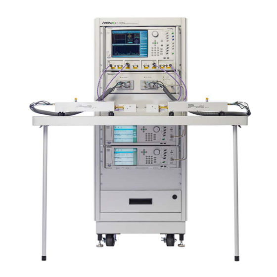
This quick start guide provides a brief overview of the ME7828A System assembly. Refer to the VectorStar™
ME7828A Series Broadband/Millimeter Wave System Installation Guide, found on the CD-ROM, for important
safety and compliance information and for more details about the assembly, configuration, setup, and test of
the equipment.
1.
Installing the Instruments into the Console
VectorStar
MS4640A Series
VNA
3738A Broadband
Test Set
3742A-EW T-R
Module WR-10
66670-3 WR-10
Left Coupler
MG37022A
Signal Generator
LO Source
(GPIB Address: 4)
MG37022A
Signal Generator
RF Source
(GPIB Address: 5)
Figure 1.
System Overview
Anritsu Company
490 Jarvis Drive
Morgan Hill, CA 95037-2809
USA
3700C3 Floor
Console
Blank Panel
3742A-EW T-R
Module WR-10
66671-3 WR-10
Right Coupler
Console Table
Blank Panel
Floor Console
Drawer
Part Number: 10410-00289
Revision: B
Published: June 2009
Copyright 2007-2009 Anritsu Company
Advertisement

Related Manuals for Anritsu VectorStar ME7828A Series


Summary of Contents for Anritsu VectorStar ME7828A Series
- Page 1 (GPIB Address: 4) Blank Panel MG37022A Floor Console Signal Generator Drawer RF Source (GPIB Address: 5) Figure 1. System Overview Anritsu Company Part Number: 10410-00289 490 Jarvis Drive Revision: B Morgan Hill, CA 95037-2809 Published: June 2009 Copyright 2007-2009 Anritsu Company...
- Page 2 Assembling the Console Table Figure 2. Console Table Assembly Connecting the Rear Panel Control and BNC Cabling The illustration below shows the rear panel control and GPIB cabling between the MS4640A Series VNA and the 3738A Test Set (left), and the BNC cabling between the MS4040A Series VNA and the two MG37022A Signal Generators (right).
- Page 3 Connecting the Test Set to the Signal Generators and WR-10 mmW Modules The illustration below shows the RF and LO cables between the Signal Generators and the Test Set, and the 54094 Cable Assembly connection between the Test Set and the WR-10 mmW modules. MS4640A 3738A Test Set...
- Page 4 Connecting the VNA to the 3642A-EW Combiners The illustration below shows the MS4640A b1 and b2 input and Port 1 and Port 2 output connections to the 3742A-EW Combiners. MS4640A Port 2 b2 Input b1 Input Port 1 b1 V (m-m) Cable b2 V (m-m) Cable 806-207 806-207...
Need help?
Do you have a question about the VectorStar ME7828A Series and is the answer not in the manual?
Questions and answers