Anritsu VectorStar ME7848A Quick Start Manual
Opto-electronic network analyzer systems
Hide thumbs
Also See for VectorStar ME7848A:
- Maintenance manual (80 pages) ,
- Maintenance manual (90 pages) ,
- Maintenance manual (128 pages)
Table of Contents
Advertisement
Quick Links
Quick Start Guide
Opto-electronic Network Analyzer
Systems
ME7848A-0240, 40 GHz 850 nm System
ME7848A-0270, 70 GHz 1550 nm System
ME7848A-0271, 70 GHz 1310 nm System
ME7848A-0140 40 GHz, 850 nm System (VNA and O/E module only)
ME7848A-0170 70 GHz, 1550 nm System (VNA and O/E module only)
ME7848A-0171 70 GHz, 1310 nm System (VNA and O/E module only)
Anritsu Company
490 Jarvis Drive
Morgan Hill, CA 95037-2809
USA
http://www.anritsu.com
Part Number: 10410-00777
Published: November 2019
Copyright 2019 Anritsu Company. All rights reserved.
Revision: A
Advertisement
Table of Contents

Related Manuals for Anritsu VectorStar ME7848A


Summary of Contents for Anritsu VectorStar ME7848A
- Page 1 ME7848A-0170 70 GHz, 1550 nm System (VNA and O/E module only) ME7848A-0171 70 GHz, 1310 nm System (VNA and O/E module only) Anritsu Company Part Number: 10410-00777 490 Jarvis Drive Revision: A Morgan Hill, CA 95037-2809 Published: November 2019 Copyright 2019 Anritsu Company. All rights reserved. http://www.anritsu.com...
- Page 2 ® measurement information is contained in the VectorStar Calibration and Measurement Guide – 10410-00318. This document and all other documentation that supports the ME7848A is available on the Anritsu web site: http://www.anritsu.com/ Minimum Configurations The following are the configurations for the -02xx opto-electronic network analyzer systems. The -01xx systems...
-
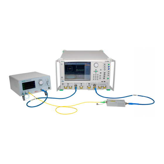
Page 3: System Connections
2. System Connections Table 1. ME7848A ONA System Configuration Options (2 of 2) MS4747B 70 GHz VectorStar VNA with Option 051, 061, or 062 MN4765B-0071 70 GHz 1310 Calibration Module (with characterization files) MN4775A-0071 70 GHz 1310 nm E/O Converter 2000-1958-R Accessory Kit which includes: ME7848A-0271 70 GHz 1310 nm System •... - Page 4 2. System Connections An optical patch cord is used to connect the E/O converter to the O/E module. The MN4765B is connectorized for FC/APC fiber (and those patch cord connections are often denoted by a green boot). The MN4775A (and many other modulators) is connectorized for FC/PC fiber (and those connections are often denoted by a white boot).
- Page 5 2. System Connections The MN4775A (and equivalent units) contain a laser and are accompanied by a warning label like that shown Figure 3. The MN4775A-007x are class 1M and the MN4775A-0040 is class 3B (due to the shorter wavelength). Figure 3. Laser Warning Labels Examples In addition to the above basic setup, it is possible to improve dynamic range of the measurement in certain frequency ranges but altering some basic connections to effectively ‘reverse’...
-
Page 6: System Check
3. System Check System Check Initial Settings 1. Begin with the VNA in a Preset state and then set up for the measurement: a. Set test port power to +5 dBm (POWER Menu) for -0240 systems and -10 dBm for the -027x systems. -
Page 7: Functional Test
3. System Check Figure 6. Example Plot of |S21| for the System Check on a ME7848A-0270 System at +5 and +2 dBm Optical Power Levels. The absolute values and approximate shape are of interest. Figure 6, the blue curve is at 5 dBm optical power out of the modulator which is the test condition mentioned above. - Page 8 4. Making Opto-electronic Component Measurements 3. The response is the absolute detected power and will have a similar shape to the |S21| plots in the previous section but the numerical levels will be different. Figure 7. Example Plot of the Functional Test at +5 and +2 dBm Optical Power Levels An example plot of the functional test is shown in Figure 7 for the ME7848A-0270 system at +5 dBm optical...
- Page 9 4. Making Opto-electronic Component Measurements • To study individual components (i.e., an E/O converter of interest is to be inserted into the path), the other components need to be de-embedded. There are many ways to start this process, but for reasons of maximum accuracy and traceability, the MN4765B O/E module is delivered with a characterization file describing its behavior).
- Page 10 4. Making Opto-electronic Component Measurements Figure 8. E/O Measurement Dialog O/E Measurements In this case, the E/O device must be de-embedded. Sometimes, the .s2p file of that device is available but, if not, a two-step process is used. The MN4765B is connected to the E/O device (the MN4775A usually) and the VNA tools are used to generate the .s2p file for the MN4775A by de-embedding the MN4765B.
-
Page 11: Regulatory Compliance
In addition to the VectorStar Calibration and Measurement Guide, additional white papers (such as Wideband Optical Modulator and Detector Characterization, available on the Anritsu website) and application notes are available that discuss this measurement class. - Page 12 Anritsu Company 490 Jarvis Drive Anritsu utilizes recycled paper and environmentally conscious inks and toner. Morgan Hill, CA 95037-2809 http://www.anritsu.com...
Need help?
Do you have a question about the VectorStar ME7848A and is the answer not in the manual?
Questions and answers