Anritsu VectorStar ME7838A4 Installation Manual
Multiport broadband/banded vector network analyzers
Hide thumbs
Also See for VectorStar ME7838A4:
- Maintenance manual (138 pages) ,
- Maintenance manual (138 pages)
Table of Contents
Advertisement
Quick Links
Installation Guide
VectorStar™ ME7838x4 Series
Multiport Broadband/Banded
Vector Network Analyzers
High Performance Modular Broadband/Banded Millimeter-Wave
Vector Network Analyzer (VNA) Multiport Measurement System
ME7838A4, 70 kHz to 110 (125) GHz
ME7838E4, 70 kHz to 110 GHz
ME7838D4, 70 kHz to 145 (150) GHz
ME7838G4, 70 kHz to 220 (226) GHz
Anritsu Company
Part Number: 10410-00734
490 Jarvis Drive
Revision: D
Morgan Hill, CA 95037-2809
Published: February 2021
USA
Copyright 2021 Anritsu Company, USA. All Rights Reserved.
http://www.anritsu.com
Advertisement
Table of Contents

Related Manuals for Anritsu VectorStar ME7838A4


Summary of Contents for Anritsu VectorStar ME7838A4
- Page 1 ME7838D4, 70 kHz to 145 (150) GHz ME7838G4, 70 kHz to 220 (226) GHz Anritsu Company Part Number: 10410-00734 490 Jarvis Drive Revision: D Morgan Hill, CA 95037-2809 Published: February 2021 Copyright 2021 Anritsu Company, USA. All Rights Reserved. http://www.anritsu.com...
- Page 2 TG-2 PN: 10410-00734 Rev. D VectorStar ME7838x4 Multiport IG...
-
Page 3: Table Of Contents
Contacting Anritsu ........ - Page 4 Table of Contents (Continued) MS464xA VNA Broadband/Banded Configuration ........3-3 Receiver Configuration for Broadband .
-
Page 5: Chapter 1 - System Overview
Appendix A — ME7838x4 Series Multiport Specifications Provides a section tab for the • VectorStar ME7838A4 Broadband/Banded mm-Wave VNA Technical Data Sheet – 11410-00704 • VectorStar ME7838D4 Broadband/Banded mm-Wave VNA Technical Data Sheet – 11410-01099 • VectorStar ME7838E4 Broadband/Banded mm-Wave VNA Technical Data Sheet – 11410-01100 •... -
Page 6: System Component Identification
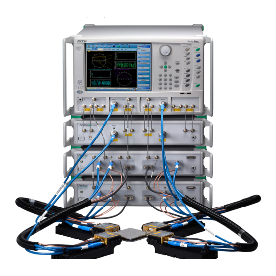
1-3 System Component Identification System Overview • Four 3744A-EE, 3744A-EW, or four OML/VDI Millimeter-Wave Modules • Front and rear panel cables System Component Identification Figure 1-1 shows the ME7838A4 Multiport System major components. Figure 1-1. ME7838A4 Multiport System, with 3743A Millimeter-Wave Modules The ME7838E4, ME7838D4, and ME7838G4 systems are the same except for the use of different Millimeter-Wave Modules (3743E, MA25300A, or MA25400A respectively). -
Page 7: System Component And Front Panel Connector Identification
System Overview 1-3 System Component Identification System Component and Front Panel Connector Identification The ME7838x4 Series Multiport System components and connectors are identified in Figure 1-2 Table 1-1. Frequency Calibration Power Measurement Sweep Application Channel MS464xA System Response File MS464xB Trace Display Help... - Page 8 1-3 System Component Identification System Overview Table 1-1. ME7838x4 Series Multiport Components and Front Panel Connectors Index Description Index Description System Components 3736B Broadband Test Set (Continued) VectorStar MS464xA (ME7838A4/D4/E4 only) LO 2 Input or MS464xB VNA MN469xC – 4 Port Test Set LO 2 Output 3736B Test Set Aux Power Source...
-
Page 9: System Rear Panel Connector Identification (Ms464Xa Vna)
System Overview 1-3 System Component Identification System Rear Panel Connector Identification (MS464xA VNA) The ME7838x4 Series Multiport System rear panel connectors are identified in Figure 1-3 Table 1-2. MS464xA 22 23 24 25 34 35 37 38 MN469xC Test Set 45 46 3736B Test Set... - Page 10 1-3 System Component Identification System Overview Table 1-2. ME7838x4 Series Multiport Components and Rear Panel Connectors (MS464xA VNA) Index Description Index Description System Bias Input – Port 2 VectorStar MS464xA VNA Bias Input – Port 1 (ME7838A4/D4/E4 only) MN469xC 4 Port Test Set MN469xC Multiport Test Set 3736B Test Set P4 Bias...
-
Page 11: System Rear Panel Connector Identification (Ms464Xb Vna)
System Overview 1-3 System Component Identification System Rear Panel Connector Identification (MS464xB VNA) The ME7838x4 Series Multiport System rear panel connectors are identified in Figure 1-4 Table 1-3. MS464xB 29 30 31 32 40 41 MN469xC Test Set 3736B Test Set IF Outputs CAUTION Do not operate with... - Page 12 1-3 System Component Identification System Overview Table 1-3. ME7838x4 Series Multiport Components and Rear Panel Connectors (MS464xB VNA) Index Description Index Description System Bias Fuse – Port 2 VectorStar MS464xB VNA Bias Fuse – Port 1 MN469xC – MultiPort Test Set Bias Input –...
-
Page 13: Millimeter-Wave Modules
System Overview 1-3 System Component Identification Millimeter-Wave Modules The 3743A, 3743E, MA25300A, or MA25400A connect to the 3736B and 3739C Test Set ports and to Test Port 1 through Test Port 4 on the MN4697C. The 3744A-xx Millimeter-Wave Modules connect only to the ports on the 3736B and 3739C Test Sets. - Page 14 1-3 System Component Identification System Overview MA25300A TEST Port Assignment Power/Signal MA25300A Millimeter Wave Module in Bracket 5 – REF SSMC Connector 1 – LO K Connector 6 – TEST SSMC Connector 2 – 0.8 mm Connector 7 – Power/Signal Latching Bi-Lobe™ connector 3 –...
-
Page 15: Me7838X4 Series Configuration Part Numbers
System Overview 1-4 ME7838x4 Series Configuration Part Numbers ME7838x4 Series Configuration Part Numbers The ME7838x4 Series Multiport VNA system configuration uses different combinations of the components listed in the table below. Additional configuration information is available in the relevant technical data sheet. Refer to Appendix A —... - Page 16 1-4 ME7838x4 Series Configuration Part Numbers System Overview Table 1-4. ME7838x4 Multiport Broadband/Millimeter-Wave VNA System Components (2 of 4) Applicable ME7838x4 System Part Number Description Specifications Millimeter-Wave Modules ME7838G4 MA25400A Broadband Millimeter-Wave Module 70 kHz to 220 (226) GHz ME7838D4 MA25300A Broadband Millimeter-Wave Module 70 kHz to 145 (150) GHz...
- Page 17 System Overview 1-4 ME7838x4 Series Configuration Part Numbers Table 1-4. ME7838x4 Multiport Broadband/Millimeter-Wave VNA System Components (3 of 4) Applicable ME7838x4 System Part Number Description Specifications Interconnect Cable Part Numbers 3-67357-18 K male-male semi-rigid cables – 3-67357-19 K male-male semi-rigid cables –...
-
Page 18: Calibration/Verification Kits
1-5 Calibration/Verification Kits System Overview Table 1-4. ME7838x4 Multiport Broadband/Millimeter-Wave VNA System Components (4 of 4) Applicable ME7838x4 System Part Number Description Specifications MS464xA (ME7838A4/D4/E4 only) or MS464xB VNA Front Panel Options 6 Front Panel Loops • Provides front and rear panel MS4647A/B-051 Front Panel Loops loops for b1, a1, Port 1... -
Page 19: Performance Specifications
VectorStar ME7838x4 Series Multiport BB/mm-Wave VNA Measurement System • VectorStar ME7838A4 Broadband/Banded mm-Wave VNA Technical Data Sheet – 11410-00704 • VectorStar ME7838D4 Broadband/Banded mm-Wave VNA Technical Data Sheet – 11410-01099 • VectorStar ME7838E4 Broadband/Banded mm-Wave VNA Technical Data Sheet – 11410-01100 •... -
Page 20: Vectorstar™ Mn469Xc Series Multiport Vna Measurement System
From here, you can select the latest sales, select service and support contact information in your country or region, provide online feedback, complete a Talk to Anritsu form to have your questions answered, or obtain other services offered by Anritsu. -
Page 21: Chapter 2 - System Assembly
Anritsu 01-204 8 mm (5/16”) End Wrench. • W1 (1 mm) and 0.8 mm Connectors Best practices recommend using an Anritsu 01-504 Torque End Wrench to tighten the 6 mm nut on W1 connectors. The correct torque setting is 0.45 N·m (4 lbf·in). -
Page 22: Required Tools
Required Tools • Anritsu 01-201 8mm (5/16”) Torque Wrench or equivalent rated at 0.9 N· m (8 lbf·in) for SMA, K, and V connectors • Anritsu 01-204 8 mm (5/16”) End Wrench or equivalent •... -
Page 23: Unpacking The Instruments
System Assembly 2-4 Unpacking the Instruments Unpacking the Instruments A MS4647A/B VNA unit is heavy. To avoid personal injury, it must be lifted and maneuvered by at least two people during installation. If mounting on a workbench surface, first position the 3739C Broadband Test Set Caution with access to its front and rear panels. -
Page 24: Rear Panel Vna Gpib Connection
2-5 Rear Panel VNA GPIB Connection System Assembly Rear Panel VNA GPIB Connection If the VNA is to be controlled over a GPIB network by a PC or other GPIB controller, install the GPIB cable to the IEEE 488.2 GPIB rear panel connector. Figure 2-1 shows an MS464xA rear panel. -
Page 25: Rear Panel Connections Between System Components (Ms464Xa Vna)
System Assembly 2-6 Rear Panel Connections Between System Components (MS464xA VNA) Rear Panel Connections Between System Components (MS464xA VNA) In this section, connect the cables between the VNA and the Test Sets as shown in Figure 2-2 Table 2-1. MS464xA MN469xC Test Set 3736B... - Page 26 2-6 Rear Panel Connections Between System Components (MS464xA VNA) System Assembly Table 2-1. ME7838x4 Multiport Rear Panel Cable Connections (MS464xA) (1 of 2) Index Part Number Cable Description Connection From Connection To MS464xA port labeled: 3736B port labeled: 3-806-225 BNC (male-male), 24 in Ext Analog Out EXT ANALOG IN MS464xA port labeled:...
- Page 27 System Assembly 2-6 Rear Panel Connections Between System Components (MS464xA VNA) Table 2-1. ME7838x4 Multiport Rear Panel Cable Connections (MS464xA) (2 of 2) Index Part Number Cable Description Connection From Connection To MS464xA port labeled: MN469xC port labeled: SMA male-male 3-62112-80 semi-rigid P1 source loop in...
-
Page 28: Rear Panel Connections Between System Components (Ms464Xb-031 Vna)
2-7 Rear Panel Connections Between System Components (MS464xB-031 VNA) System Assembly Rear Panel Connections Between System Components (MS464xB-031 VNA) In this section, connect the cables between the VNA and the Test Sets as shown in Figure 2-3 Figure 2-4, Table 2-2. -
Page 29: Cable Connections (Systems Without Option 031)
System Assembly 2-7 Rear Panel Connections Between System Components (MS464xB-031 VNA) Cable Connections (Systems without Option 031) MS464xB MN469xC Test Set 3736B Test Set IF Outputs CAUTION Do not operate with power cord ungrounded. WARNING ~ LINE INPUT 3739C No operator service- 47-63 Hz External I/O able parts inside. - Page 30 2-7 Rear Panel Connections Between System Components (MS464xB-031 VNA) System Assembly Table 2-2. ME7838x4 Multiport Rear Panel Cable Connections (MS464xB) (1 of 2) Index Part Number Cable Description Connection From Connection To MS464xB port labeled: 3736B port labeled: 3-806-225 BNC (male-male), 24 in Ext Analog Out EXT ANALOG IN VNA port labeled:...
- Page 31 System Assembly 2-7 Rear Panel Connections Between System Components (MS464xB-031 VNA) Table 2-2. ME7838x4 Multiport Rear Panel Cable Connections (MS464xB) (2 of 2) Index Part Number Cable Description Connection From Connection To MS464xB port labeled: MN469xC port labeled: SMA male-male 3-62112-80 semi-rigid P2 source loop in...
-
Page 32: Semi-Rigid Cable Connections Between System Components
2-8 Semi-rigid Cable Connections Between System Components System Assembly Semi-rigid Cable Connections Between System Components Make the semi-rigid cable connections as shown in Figure 2-5 Figure 2-6, and in Table 2-3. If your system has Option 031 Dual Source Architecture (MS464xB only), use Figure 2-5. - Page 33 System Assembly 2-8 Semi-rigid Cable Connections Between System Components Frequency Calibration Power Measurement Sweep Application Channel System Response File Trace Display Help Scale Marker Preset Standby Operate ALL PORTS: CAUTION +27 dBm MAX AVOID STATIC DISCHARGE LO 2 Figure 2-6. ME7838x4 Multiport Semi-rigid Cable Connections (without Option 031 Dual Source Architecture) VectorStar ME7838x4 Multiport IG PN: 10410-00734 Rev.
- Page 34 2-8 Semi-rigid Cable Connections Between System Components System Assembly Table 2-3. ME7838x4 Multiport semi-rigid Cable Interconnect Part Numbers and Locations (1 of 2) Index Part Numbers Description/Torque Connection From Connection To VNA port labeled: MN469xC port labeled: b1 (In) b1 (In) VNA port labeled: MN469xC port labeled: b1 (Out)
- Page 35 System Assembly 2-8 Semi-rigid Cable Connections Between System Components Table 2-3. ME7838x4 Multiport semi-rigid Cable Interconnect Part Numbers and Locations (2 of 2) Index Part Numbers Description/Torque Connection From Connection To MS464xA VNA Option 051, 061, or 062, and 08x (Banded) MS464xB VNA Option 051, 061, or 062, and 08x (Banded) MS4647A VNA...
-
Page 36: Front Panel Cable Connections
2-9 Front Panel Cable Connections System Assembly Front Panel Cable Connections Make the cable connections as shown in Figure 2-7 and in Table 2-4. ALL PORTS: CAUTION +27 dBm MAX AVOID STATIC DISCHARGE LO 2 Port 3 Port 4 Port 1 Port 2 Port 1 Port 2... - Page 37 System Assembly 2-9 Front Panel Cable Connections The cables for Test Port 1 through Test Port 4 to Module SRC are not used with modules 3744A-EE, Note 3744A-EW, or 3744A-Rx. Table 2-4. ME7838x4 Cable Interconnect Part Numbers and Locations (1 of 2) Index Part Number Description...
- Page 38 2-9 Front Panel Cable Connections System Assembly Table 2-4. ME7838x4 Cable Interconnect Part Numbers and Locations (2 of 2) Index Part Number Description Connection From Connection To MS464xA VNA – Option 051, 061, or 062, and 08x (Banded) MS464xB VNA – Option 051, 061, or 062, and 08x (Banded) MS4647A VNA –...
-
Page 39: 2-10 Front Panel To Millimeter-Wave Module Connections
System Assembly 2-10 Front Panel to Millimeter-Wave Module Connections 2-10 Front Panel to Millimeter-Wave Module Connections Connect the 3736B and 3739C Broadband Test Set test port cables to the 3743A, 3743E, MA25300A, MA25400A, 3744A-EE, 3744A-EW, or 3744A-Rx Modules as shown below, observing the correct torque limits for each connector. - Page 40 • Tighten using a torque end wrench and a plain end wrench • 6 mm Torque End Wrench set to 0.45 N·m (4 lbf·in). Recommended is Anritsu 01-504. • 6 mm / 7 mm Open End Wrench. Recommended is Anritsu 01-505.
- Page 41 SRC – V Connector (3743A module only) 806-209-R • Tighten using an 8 mm (5/16 in) torque end wrench set to 0.9 N·m (8 lbf·in). • Recommended is Anritsu 01-201. RF – V Connector (3743A, 3744A-EE, and 3744A-EW modules) 3-75685-1 •...
-
Page 42: Front Panel To Oml/Vdi Module Connections
2-11 Front Panel to OML/VDI Module Connections System Assembly 2-11 Front Panel to OML/VDI Module Connections Connect the front panel cables between the 3736B and 3739C Test Sets, and the OML or VDI frequency extension modules as shown in Figure 2-9, Figure 2-10, and... - Page 43 System Assembly 2-11 Front Panel to OML/VDI Module Connections Table 2-6. ME7838x4 OML/VDI Cable Interconnect Part Numbers and Locations Connection Index Part Number Description Connection From 3739C Test Set OML Modules: Port 1, Port 2 Port 1, Port 2 Modules Ref IF OML Module Interface Cable Assembly RF Input...
- Page 44 Ref IF – SMA Connector • Tighten using an 8 mm (5/16 in) torque end wrench set to 0.9 N·m (8 lbf·in). • Recommended is Anritsu 01-201. RF Input – SMA Connector • Tighten using an 8 mm (5/16 in) torque end wrench set to 0.9 N·m (8 lbf·in).
- Page 45 RF Input – K (2.92 mm) Connector • Tighten using an 8 mm (5/16 in) torque end wrench set to 0.9 N·m (8 lbf·in). • Recommended is Anritsu 01-201. Ref. IF – SMA Connector • Tighten using an 8 mm (5/16 in) torque end wrench set to 0.9 N·m (8 lbf·in).
- Page 46 2-11 Front Panel to OML/VDI Module Connections System Assembly 2-26 PN: 10410-00734 Rev. D VectorStar ME7838x4 Multiport IG...
-
Page 47: Chapter 3 - Me7838X4 Initial System Checkout
Chapter 3 — ME7838x4 Initial System Checkout Introduction This chapter provides the general initial system checkout for a completely assembled ME7838x4 Broadband/Banded Millimeter-Wave System. Since the ME7838x4 supports both the MS464xA and MS464xB Series VNAs, this chapter has an initial system checkout section for each VNA series: •... -
Page 48: Vna Preset Procedure
3-3 VNA Preset Procedure ME7838x4 Initial System Checkout VNA Preset Procedure 1. Depending on the instrument preset configuration, do either Step 2 Step 3 below. 2. If the VNA is configured to preset to the factory as-shipped default configuration: a. Press the VNA front panel Preset button. The VNA resets to the factory-default configuration, b. -
Page 49: Ms464Xa Vna Broadband/Banded Configuration
ME7838x4 Initial System Checkout 3-4 MS464xA VNA Broadband/Banded Configuration MS464xA VNA Broadband/Banded Configuration Receiver Configuration for Broadband Configure the VNA for Modular Broadband Operation by performing the following steps: 1. Make sure the MS4647A VNA and the 3739C/C Broadband Test Set are both on and warmed up. 2. -
Page 50: 3739 Setup For Broadband
3-4 MS464xA VNA Broadband/Banded Configuration ME7838x4 Initial System Checkout 3739 Setup for Broadband Configure the VectorStar VNA for Broadband Operation by performing the following steps: 1. Make sure the VNA and the broadband test set are both on and warmed up. 2. -
Page 51: Frequency Setup
ME7838x4 Initial System Checkout 3-4 MS464xA VNA Broadband/Banded Configuration Frequency Setup 1. Navigate to the FREQUENCY menu. • MAIN | Frequency | FREQUENCY 2. At the FREQUENCY menu, set the following frequency parameters: • Start Frequency = 70.000000000 kHz • Stop Frequency = 125.000000000 GHz •... -
Page 52: Receiver Configuration For Multiple Source
3-4 MS464xA VNA Broadband/Banded Configuration ME7838x4 Initial System Checkout Receiver Configuration for Multiple Source Configure the VectorStar VNA for Multiple Source Broadband Operation by performing the following steps: 1. Make sure the VNA and the broadband test set are both on and warmed up. 2. -
Page 53: 3739 Setup For Banded Modules
ME7838x4 Initial System Checkout 3-4 MS464xA VNA Broadband/Banded Configuration 3739 Setup for Banded Modules Configure the VectorStar VNA for BB/mmWave Operation by performing the following steps: 1. Make sure the VNA and the broadband test set are both on and warmed up. 2. -
Page 54: 3739 Setup For Oml/Vdi Selection
3-4 MS464xA VNA Broadband/Banded Configuration ME7838x4 Initial System Checkout 3739 Setup for OML/VDI Selection Configure the VectorStar VNA for OML or VDI operation by performing the following steps: 1. Make sure the VNA and the broadband test set are both on and warmed up. 2. -
Page 55: Oml Band Selection
ME7838x4 Initial System Checkout 3-4 MS464xA VNA Broadband/Banded Configuration OML Band Selection Configure the VectorStar VNA for OML operation by performing the following steps: 1. Make sure the VNA and the broadband test set are both on and warmed up. 2. -
Page 56: Vdi Band Selection
3-4 MS464xA VNA Broadband/Banded Configuration ME7838x4 Initial System Checkout VDI Band Selection Configure the VectorStar VNA for VDI operation by performing the following steps: 1. Make sure the VNA and the broadband test set are both on and warmed up. 2. -
Page 57: Ms464Xb Vna Broadband/Banded Configuration
ME7838x4 Initial System Checkout 3-5 MS464xB VNA Broadband/Banded Configuration MS464xB VNA Broadband/Banded Configuration Configure the VNA for Modular Broadband Operation by performing the following steps: 1. Make sure the VNA and the broadband test set are both on and warmed up. 2. -
Page 58: 3739 Setup For Broadband
3-5 MS464xB VNA Broadband/Banded Configuration ME7838x4 Initial System Checkout 3739 Setup for Broadband Configure the VectorStar VNA for Broadband Operation by performing the following steps: 1. Make sure the VNA and the broadband test set are both on and warmed up. 2. -
Page 59: Frequency Setup
ME7838x4 Initial System Checkout 3-5 MS464xB VNA Broadband/Banded Configuration Frequency Setup 1. Navigate to the FREQUENCY menu. • MAIN | Frequency | FREQUENCY 2. At the FREQUENCY menu, set the frequency parameters, as shown in Table 3-1 Figure 3-11. Table 3-1. Frequency Parameters to Set 70.000000000 kHz 70.000000000 kHz... - Page 60 3-5 MS464xB VNA Broadband/Banded Configuration ME7838x4 Initial System Checkout 4. The system should now be sweeping fully from the set Start Frequency and Stop Frequency. Figure 3-11. FREQUENCY Menu – Example for Settings for 70 kHz to 125 GHz Sweep 3-14 PN: 10410-00734 Rev.
-
Page 61: Receiver Configuration For Multiple Source
ME7838x4 Initial System Checkout 3-5 MS464xB VNA Broadband/Banded Configuration Receiver Configuration for Multiple Source Configure the VectorStar VNA for Multiple Source Broadband Operation by performing the following steps: 1. Make sure the VNA and the broadband test set are both on and warmed up. 2. - Page 62 3-5 MS464xB VNA Broadband/Banded Configuration ME7838x4 Initial System Checkout Figure 3-12. Receiver Configuration for Multiple Source (MS464xB Menu) (2 of 2) 3-16 PN: 10410-00734 Rev. D VectorStar ME7838x4 Multiport IG...
-
Page 63: 3739 Setup For Banded Modules
ME7838x4 Initial System Checkout 3-5 MS464xB VNA Broadband/Banded Configuration 3739 Setup for Banded Modules Configure the VectorStar VNA for BB/mmWave Operation by performing the following steps: 1. Make sure the VNA and the broadband test set are both on and warmed up. 2. -
Page 64: 3739 Setup For Oml/Vdi Selection
3-5 MS464xB VNA Broadband/Banded Configuration ME7838x4 Initial System Checkout 3739 Setup for OML/VDI Selection Configure the VectorStar VNA for OML or VDI operation by performing the following steps: 1. Make sure the VNA and the broadband test set are both on and warmed up. 2. -
Page 65: Oml Band Selection
ME7838x4 Initial System Checkout 3-5 MS464xB VNA Broadband/Banded Configuration OML Band Selection Configure the VectorStar VNA for OML operation by performing the following steps: 1. Make sure the VNA and the broadband test set are both on and warmed up. 2. -
Page 66: Vdi Band Selection
3-5 MS464xB VNA Broadband/Banded Configuration ME7838x4 Initial System Checkout VDI Band Selection Configure the VectorStar VNA for VDI operation by performing the following steps: 1. Make sure the VNA and the broadband test set are both on and warmed up. 2. -
Page 67: Me7838X4 Configuration Verification - Bb/Mmwave Modules
ME7838x4 Initial System Checkout 3-6 ME7838x4 Configuration Verification – BB/mmWave Modules ME7838x4 Configuration Verification – BB/mmWave Modules This verification procedure applies when using 3743A, 3743E, MA25300A, or MA25400A broadband Note modules. 1. Ensure the system is sweeping from: • 70 kHz to 125 GHz for the ME7838A4 system •... - Page 68 3-6 ME7838x4 Configuration Verification – BB/mmWave Modules ME7838x4 Initial System Checkout Non-Ratioed Parameters for Initial Checkout Figure 3-17. Typical Four-Trace Display – Shorts on Port 1 and Port 2 – ME7838A4 3-22 PN: 10410-00734 Rev. D VectorStar ME7838x4 Multiport IG...
- Page 69 ME7838x4 Initial System Checkout 3-6 ME7838x4 Configuration Verification – BB/mmWave Modules Non-Ratioed Parameters for Initial Checkout Figure 3-18. Typical Four-Trace Display – Shorts on Port 1 and Port 2 – ME7838D4 Non-Ratioed Parameters for Initial Checkout Figure 3-19. Typical Four-Trace Display – Shorts on Port 1 and Port 2 – ME7838E4 VectorStar ME7838x4 Multiport IG PN: 10410-00734 Rev.
- Page 70 3-6 ME7838x4 Configuration Verification – BB/mmWave Modules ME7838x4 Initial System Checkout Non-Ratioed Parameters for Initial Checkout Figure 3-20. Typical Four-Trace Display – Shorts on Port 1 and Port 2 – ME7838G4 9. Select Trace 1 and then select Response | RESPONSE | User-defined. The USER-DEFINED menu appears. a.
- Page 71 ME7838x4 Initial System Checkout 3-6 ME7838x4 Configuration Verification – BB/mmWave Modules 13. Connect shorts to module ports 3 and 4 (for the ME7838G4, just leave the coaxial flange ports open), and ensure the resultant display looks similar to: • Figure 3-21 (125 GHz shown) for ME7838A4 •...
- Page 72 3-6 ME7838x4 Configuration Verification – BB/mmWave Modules ME7838x4 Initial System Checkout Non-Ratioed Parameters for Initial Checkout Figure 3-22. Typical Four-Trace Display – Shorts on Port 3 and Port 4 – ME7838D4 3-26 PN: 10410-00734 Rev. D VectorStar ME7838x4 Multiport IG...
- Page 73 ME7838x4 Initial System Checkout 3-6 ME7838x4 Configuration Verification – BB/mmWave Modules Non-Ratioed Parameters for Initial Checkout Figure 3-23. Typical Four-Trace Display – Shorts on Port 3 and Port 4 – ME7838E4 VectorStar ME7838x4 Multiport IG PN: 10410-00734 Rev. D 3-27...
- Page 74 3-6 ME7838x4 Configuration Verification – BB/mmWave Modules ME7838x4 Initial System Checkout Non-Ratioed Parameters for Initial Checkout Figure 3-24. Typical Four-Trace Display – Shorts on Port 3 and Port 4 – ME7838G4 VNA Power Down 1. With the VNA in operate mode, the front panel Standby/Operate button is illuminated with a green LED. 2.
-
Page 75: Appendix A - Me7838X4 Series Multiport Specifications
ME7838x4 VNA System Specifications The latest technical data sheets and other reference materials for the ME7838x4, MS464xA/B, and other VectorStar™ VNA systems can be downloaded from http://www.anritsu.com. The recommended documents are: • VectorStar™ ME7838A4 Broadband/Banded mm-Wave VNA Technical Data Sheet – 11410-00704 •... - Page 76 A-1 ME7838x4 VNA System Specifications ME7838x4 Series Multiport Specifications PN: 10410-00734 Rev. D VectorStar ME7838x4 Multiport IG...
- Page 77 QSG ........1-15 Anritsu, contact ......1-16 10410-00771 ME7838E4 BB/mm QSG .
- Page 78 MS464xB VNA UIRM 10410-00319 ..1-15 Links contacting Anritsu ....1-16 Non-Ratioed Parameters 3-22, 3-23, 3-24, 3-25, 3-26, 3-27, .
- Page 79 Trace Settings ..... . . 3-21, 3-24 URL, Contacting Anritsu ....1-16 VDI Module Cable Connections .
- Page 80 Index-4 PN: 10410-00734 Rev. D VectorStar ME7838x4 Multiport IG...
- Page 82 Anritsu Company 490 Jarvis Drive Anritsu utilizes recycled paper and environmentally conscious inks and toner. Morgan Hill, CA 95037-2809 http://www.anritsu.com...
Need help?
Do you have a question about the VectorStar ME7838A4 and is the answer not in the manual?
Questions and answers