Advertisement
TM
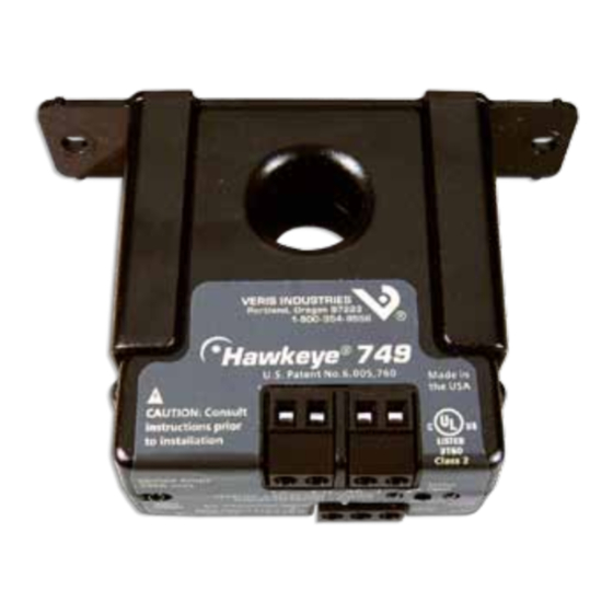
H749
DANGER
HAZARD OF ELECTRIC SHOCK, EXPLOSION, OR ARC FLASH
• Follow safe electrical work practices. See NFPA 70E in the USA, or applicable local codes.
• This equipment must only be installed and serviced by qualified electrical personnel.
• Read, understand and follow the instructions before installing this product.
• Turn off all power supplying equipment before working on or inside the equipment.
• Use a properly rated voltage sensing device to confirm power is off.
DO NOT DEPEND ON THIS PRODUCT FOR VOLTAGE INDICATION
• Only install this product on insulated conductors.
Failure to follow these instructions will result in death or serious injury.
NOTICE
• This product is not intended for life or safety applications.
• Do not install this product in hazardous or classified locations.
• The installer is responsible for conformance to all applicable codes.
• Mount this product inside a suitable fire and electrical enclosure.
Wiring ExamplE
CONTROLLER
DI
(Status)
DO
(Relay
Coil)
CONTROL
POWER
Z201491-0A
PAGE 1
Alta Labs, Enercept, Enspector, Hawkeye, Trustat, Veris, and the Veris 'V' logo are trademarks or registered trademarks of Veris Industries, L.L.C. in the USA and/or other countries.
CURRENT MONITORING
CONTACTOR
Fan or Pump
Motor
©2012 Veris Industries USA 800.354.8556 or +1.503.598.4564 / support@veris.com
INSTALLATION GUIDE
Solid-Core Current Switch, Adjustable Trip Point
With Command Relay, 120VAC/DC Status Output
Installer's Specifications
Amperage Range
Sensor Power
Insulation Class
Frequency Range
Temperature Range
Humidity Range
Hysteresis
Terminal Block Maximum WIre Size
Terminal Block Torque (nominal)
Status Output
Relay Coil
Relay Contact
Resistive: 8 A@250 VAC, 30 VDC; Inductive: 3.5 A@250 VAC, 30 VDC
Agency Approvals
Do not use the LED status indicators as evidence of applied voltage.
The product design provides for basic insulation only.
installation
Disconnect and lock out power to the enclosure containing the
conductor to be monitored.
1. Locate a mounting surface for the removable mounting bracket that will allow
the monitored conductor to pass through the center window when it is installed
and that will keep the device at least 1/2" from any uninsulated conductors.
Determine cable routing for the controller connection, allowing wiring to reach
the mounting location.
2. Route the conductor through the sensor's center window and slip the assembly
into the mounting bracket. Terminate the conductor. See Notes (page 2) for
currents under 1 Amp or above 135 Amps.
3. Wire the output connections to the DDC controller or switched load (solid state
contact).
4. Secure enclosure and reconnect power.
5. Calibrate the sensor (see Calibration section).
DimEnsions
Removable/Adjustable Mounting Bracket
0.7"
(19 mm)
0.2" x 0.15"
slot (2x)
749
TM
1-135 A continuous
Induced from monitored current
600 VAC RMS
-15° to 60°C (5° to 140°F)
10-90% RH non-condensing
10% of setpoint, typical
4 in-lbs (0.45 N-m)
N.O. 0.2 A@120 VAC/DC
24 VAC/DC, 10 mA
UL508 E150462
0.9"
(23 mm)
3.0"
(75 mm)
2.8"
(68 mm)
1.1"
(27 mm)
3.8"
(95 mm)
4.2"
(106 mm)
50/60 Hz
14 AWG
02121
Advertisement
Table of Contents

Related Manuals for Veris Industries Hawkeye H749


Summary of Contents for Veris Industries Hawkeye H749
- Page 1 Z201491-0A PAGE 1 ©2012 Veris Industries USA 800.354.8556 or +1.503.598.4564 / support@veris.com 02121 Alta Labs, Enercept, Enspector, Hawkeye, Trustat, Veris, and the Veris ‘V’ logo are trademarks or registered trademarks of Veris Industries, L.L.C. in the USA and/or other countries.
- Page 2 Z201491-0A PAGE 2 ©2012 Veris Industries USA 800.354.8556 or +1.503.598.4564 / support@veris.com 02121 Alta Labs, Enercept, Enspector, Hawkeye, Trustat, Veris, and the Veris ‘V’ logo are trademarks or registered trademarks of Veris Industries, L.L.C. in the USA and/or other countries.
Need help?
Do you have a question about the Hawkeye H749 and is the answer not in the manual?
Questions and answers