Table of Contents
Advertisement
Quick Links
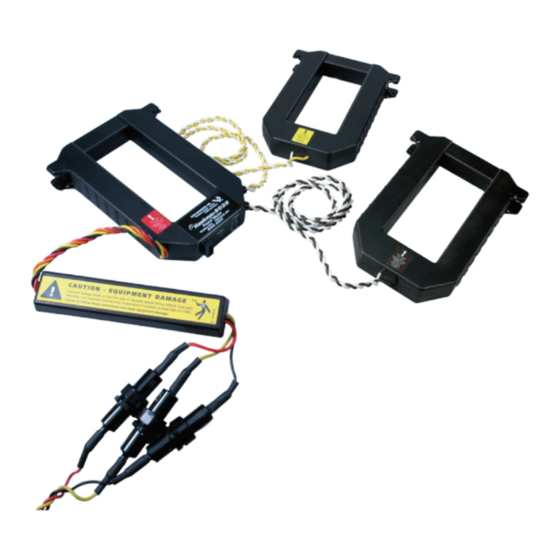
EnErcEpt® H8035/H8036
Modbus Energy Meter
Networked kW/kWh Transducers
Z201686-0G
page 1
POWER MONITORING
US Patent No. 6,373,238
©2008 Veris Industries USA 800.354.8556 or 503.598.4564 / support@veris.com
INSTALLATION GUIDE
Installer's Specifications
Input Voltage
Number of Phases Monitored
Frequency
Maximum Primary Current
CT case isolation
Internal isolation
Operating temp. range
Storage temp. range
Accuracy
±1% of reading from 10% to 100% of the rated current*
Output Type
Baud Rate
Protocol
* Meter accuracy specified with conductors centered in the CT window.
quick install
Disconnect and lock out power before installation.
1.
Set the address switches located on the bottom of the CT.
2.
Connect the voltage leads to the source to be monitored.
3.
Snap the CT onto the conductor (observe color matching).
4.
Connect the Modbus wires (observe polarity).
208 to 480 VAC
100/300/400/800/1600/2400 A continuous per phase
0° to 60°C (32° to 122°F) (<95%RH, non-condensing)
-40° to 70°C (-40° to 158°F)
RS-485, 2-wire plus common
1 or 3
50/60 Hz
600 VAC
2000 VAC rms
9600
Modbus RTU
07083
Advertisement
Table of Contents

Related Manuals for Veris Industries ENERCEPT H8035


Summary of Contents for Veris Industries ENERCEPT H8035
- Page 1 Set the address switches located on the bottom of the CT. Connect the voltage leads to the source to be monitored. Snap the CT onto the conductor (observe color matching). Connect the Modbus wires (observe polarity). Z201686-0G page 1 ©2008 Veris Industries USA 800.354.8556 or 503.598.4564 / support@veris.com 07083...
-
Page 2: Product Identification
5.5" (139 mm) 2.5" (62 mm) H8035-1600-4 1600 LARGE 1.2" (30 mm) H8035-2400-4 2400 LARGE 7.9" (201 mm) 6.0" (151 mm) *H8035 models work with H8920-5 LON nodes Z201686-0G page 2 ©2008 Veris Industries USA 800.354.8556 or 503.598.4564 / support@veris.com 07083... -
Page 3: Operation
Color match CTs and voltage leads! Example: clamp the kW = Horsepower x 0.746 red labeled CT around the power conductor connected to the red voltage wire. Z201686-0G page 3 ©2008 Veris Industries USA 800.354.8556 or 503.598.4564 / support@veris.com 07083... - Page 4 To additional MODBUS Devices Note: The meter cannot communicate on the network bus without power. Therefore, it is best to connect the voltage leads ahead of switching devices. Z201686-0G page 4 ©2008 Veris Industries USA 800.354.8556 or 503.598.4564 / support@veris.com 07083...
-
Page 5: Address Selection Switches
Each Modbus device must have a unique address. These switches must be set to assign a unique address before the device is connected to the Modbus RS-485 line. If an address is selected which conflicts with another device, both devices will be unable to communicate. Z201686-0G page 5 ©2008 Veris Industries USA 800.354.8556 or 503.598.4564 / support@veris.com 07083... -
Page 6: Modbus Register Addressing
Voltage, line to neutral 40009 AMPS Current 40010 Demand (power), phase A 40011 Demand (power), phase B 40012 Demand (power), phase C 40013 Power Factor, phase A Z201686-0G page 6 ©2008 Veris Industries USA 800.354.8556 or 503.598.4564 / support@veris.com 07083... - Page 7 Voltage, line to neutral 40273 AMPS Current 40274 AMPS Current 40275 Demand (power), phase A 40276 Demand (power), phase A 40277 Demand (power), phase B 40278 Demand (power), phase B Z201686-0G page 7 ©2008 Veris Industries USA 800.354.8556 or 503.598.4564 / support@veris.com 07083...
- Page 8 In many applications, a single Modbus command is used to read all of the data available from the meter. For integers, the beginning address is 40001 (or zero in the Z201686-0G page 8 ©2008 Veris Industries USA 800.354.8556 or 503.598.4564 / support@veris.com 07083...
- Page 9 0.0625 0.1250 40024 AMPS 3.906E-03 0.015625 0.03125 0.0625 0.1250 40025 0.004 0.016 0.032 0.064 0.128 40026 0.004 0.016 0.032 0.064 0.128 40027 0.004 0.016 0.032 0.064 0.128 Z201686-0G page 9 ©2008 Veris Industries USA 800.354.8556 or 503.598.4564 / support@veris.com 07083...
- Page 10 40019 VOLTS 40020 VOLTS 40021 VOLTS 40022 AMPS 40023 AMPS 40024 AMPS 40025 62.5 31.25 15.625 7.8125 40026 62.5 31.25 15.625 7.8125 40027 62.5 31.25 15.625 7.8125 Z201686-0G page 10 ©2008 Veris Industries USA 800.354.8556 or 503.598.4564 / support@veris.com 07083...
-
Page 11: Troubleshooting
0.5. The meter can accurately measure these low PFs, but few loads operate normally at such a low power factor. Z201686-0G page 11 ©2008 Veris Industries USA 800.354.8556 or 503.598.4564 / support@veris.com 07083...
Need help?
Do you have a question about the ENERCEPT H8035 and is the answer not in the manual?
Questions and answers