
Related Manuals for Hyco Microboil Smart MS3W


Summary of Contents for Hyco Microboil Smart MS3W
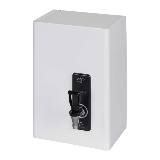
- Page 1 Product Instruction Manual Microboil Smart MS3W, MS3SS MS6W, MS6SS MS10W, MS10SS Wall Mounted Boiling Water Heater v23.11.1...
-
Page 2: Important Safety Points
Overview Thank you for purchasing a Microboil Smart wall mounted boiling water heater. Available in 3, 6 and 10 litre capacities, it will provide hot water for making tea and coffee in the work place. Please read and follow these instructions to ensure that installation and operation are as simple and safe as possible. - Page 3 This appliance must be earthed. This appliance is intended to be permanently connected to the water mains and should not be connected by a detachable hose-set. Only connect this appliance to a water supply that meets the min/max pressures specified in the specifications section of this manual. Do not confuse the vent and the inlet pipes –...
-
Page 4: Installation
1. Installation 1(a) Remove the Cover Diagram 1 • The cover is attached to the back frame by means of two screws at the base and top of the appliance (see Diagram 1). 1(b) Select Mounting Position Ensure the mounting surface is suitable for the weight of the appliance when full. Parts of this appliance –... - Page 5 • Units are typically mounted above a draining board or drip tray in a kitchen or similar setting. The tap height should be convenient for both the operator and such that visual contact is maintained with the liquid level of any vessel being filled. •...
-
Page 6: Plumbing Connection
2. Plumbing Connection This appliance is intended to be permanently connected to the water mains and should not be connected by a detachable hose-set. Only connect this appliance to a water supply that meets the min/max pressures specified in the specifications section of this manual. Any plastic pipework or fittings connected to the vent pipe must be rated to 100°C minimum. - Page 7 • All models will take 15mm pipe by means of compression fittings. • Connect the cold water supply to the inlet connection below the solenoid valve (see Diagram 4). Solenoid valve Diagram 4 • For the vent connection it is important that the vent pipe installation adheres to the following specification ;...
- Page 8 Diagram 5 3. Refitting the Cover and Installing the Tap • Slide the cover back over the appliance, taking care not to trap the vent tube at the side of the appliance. Then secure with the 4 cover screws (see Diagram 1). •...
-
Page 9: Electrical Connection
4. Electrical Connection The appliance must be permanently connected to the electrical supply through an appropriately rated isolating switch with a contact separation in all poles Only connect the appliance to an electrical supply that meets the specification detailed on the rating label. This appliance must be earthed. -
Page 10: Operation
5. Commissioning (first power on) • Ensure water supply is on. • Switch power on. • Automatic commissioning will then commence under the control of the electronic circuit board. The (automatic) stages in commissioning are as follows: • At first power on, the water tank will completely fill with cold water through the solenoid valve. -
Page 11: Smart Technology
• The Microboil Smart is fitted with a two way tap. • For instant boiling water for cups of tea and coffee gently pull the top of the tap forward. Boiling water will flow until the tap handle is released. This mode of operation gives precision control for safe filling. -
Page 12: Cleaning And Maintenance
8. Cleaning and Maintenance The appliance should only be installed and maintained by a competent person in accordance with any local electrical and plumbing regulations. Cleaning and maintenance shall not be made by children without supervision. Do not use abrasive or corrosive chemicals to clean this appliance. Use a soft damp cloth when cleaning the cover, avoid excessive use of liquids. - Page 13 Diagram 9 • To aid de-scaling, the appliance has a drain plug which can be found on the underside of the water tank behind the bottom insulation. This is accessed by removing the plastic clips and pulling the insulation down and forward (see Diagrams 10 and 11).
- Page 14 9. Advanced Information Reversing the Inlet and Vent Positions The appliance should only be installed and maintained by a competent person in accordance with any local electrical and plumbing regulations. Always switch electrical power off if the water supply needs to be disconnected for more than a few minutes.
-
Page 15: Control Board Settings
• Place the solenoid through the remaining hole in the mounting bracket next to the vent and secure with the two screws. • Refit the brass reducer to the solenoid valve, it is best practice to renew the fibre washer when refitting. •... -
Page 16: Spare Parts Diagram
10. Spare Parts Diagram... -
Page 17: Spare Parts List
11. Spare Parts List Diagram Part Code Description Reference MS_GASKET_V1 Microboil Smart gasket MS_ELEMENT_V1 Microboil Smart element MS_TAPSET_V1 Microboil Smart full tap MS_TAPHANDLE_V1 Microboil Smart tap handle MS_TAPSILICONE_V1 Microboil Smart tap silicone MS_CUTOUT_V1 Microboil Smart thermal cut out MS_SOLENOID_V1 Microboil Smart solenoid valve MS_PCB_V1 Microboil Smart PCB MS_TANKCAP_V1... -
Page 18: Specification
12. Specification Model MS3W/SS MS6W/SS MS10W/SS Power 2.84 kW 2.84 kW 2.84 kW Initial draw off (Cups/Mugs)* 18/12 36/24 62/42 Heat up time 6 mins 12 mins 20 mins Recovery rate (Cups/hr) Voltage 230 V~ 230 V~ 230 V~ Frequency 50 Hz 50 Hz 50 Hz... -
Page 19: Troubleshooting
If there is a manufacturing defect within the warranty period hyco will in its sole discretion replace, repair or refund any faulty unit. Incorrect installation, frost damage, the consequences of limescale deposits or failure to follow correct operating and maintenance instructions are excluded. - Page 20 In order to underline the duty to dispose of this equipment separately, the product is marked with a crossed out dustbin. Hyco Manufacturing Ltd Normandy Court Express Way...
Need help?
Do you have a question about the Microboil Smart MS3W and is the answer not in the manual?
Questions and answers