
Subscribe to Our Youtube Channel
Related Manuals for Kobold KEP-2


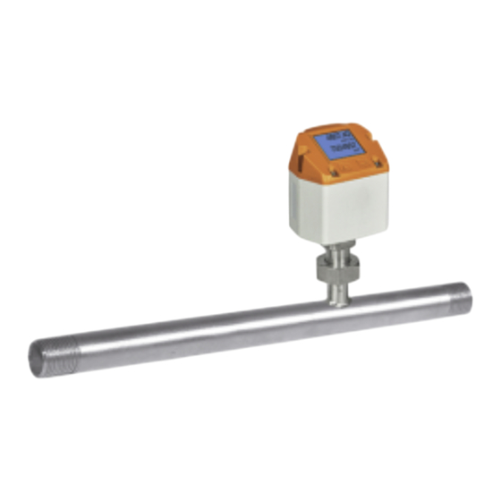
Summary of Contents for Kobold KEP-2
- Page 1 Operating Instructions Thermal Flow Meter for bi-directional measurements Model: KEP-2...
-
Page 2: Table Of Contents
Installation Description ................... 9 Pipe/tube requirements ................ 9 Inlet / outlet runs .................. 9 Installation of KEP-2 ................10 Displayhead Position ................. 10 Flow measuring ranges ................11 ... - Page 3 KEP-2 bi-directional Disposal ...................... 39 EU Declaration of Conformance ..............40 Manufactured and sold by: Kobold Messring GmbH Nordring 22-24 D-65719 Hofheim Tel.: +49(0)6192-2990 Fax: +49(0)6192-23398 E-Mail: info.de@kobold.com Internet: www.kobold.com KEP-2 bi-directional K01/0124 page 3...
-
Page 4: Note
Please read these operating instructions before unpacking and putting the unit into operation. Follow the instructions precisely as described herein. The instruction manuals on our website www.kobold.com are always for currently manufactured version of our products. Due to technical changes, the instruction manuals available online may not always correspond to the product version you have purchased. -
Page 5: Regulation Use
Therefore, any resulting damage is not the responsibility of the manufacturer. The user assumes all risk for such usage. The KEP-2 consumption sensor for bi-directional measurements is used for continuous flow measurement in both directions. The KEP-2 consumption sensor for bi-directional measurements is designed and constructed exclusively for the intended purpose described here and may only be used accordingly. -
Page 6: Operating Principle
KEP-2 bi-directional 5. Operating Principle The KEP-2 is a compact consumption counter for compressed air and gases. Special features: Optimum accuracy due to compact design Integrated Display showing Flow, consumption, velocity and temperature for two directions Input inner tube diameter via display keys ... - Page 7 We offer you to take back the instruments of the instrument’s family KEP-2 which you would like to dispose of. Qualified employees from the measurement and control technology branch should only carry out adjustments and calibrations.
-
Page 8: Scaling Analogue Output Compressed Air
Reference DIN1945/ ISO 1217: 20°C, 1000 mbar (Reference during calibration) Description Version Analogue output Low Speed 0…25 l/min Standard 0…50 l/min KEP-2 with integrated ¼“ meas. section 4…20 mA = 0…105 l/min High Speed 0…130 l/min Low Speed 0...20 m³/h Standard 0...45 m³/h... -
Page 9: Installation Description
(pipe expands towards the meas. section) 90° bend 15 x D or T-piece 2 bends á 90° 20 x D on one level 2 bends á 90° 35 x D 3-dimensional change of direction Shut-off valve 45 x D KEP-2 bi-directional K01/0124 page 9... -
Page 10: Installation Of Kep-2
Attention: The dimensions of the KEP-2 consumption counter measuring sections do not fullfill the required minimum lengths of the input and outlet runs. Please ensure recommended in - and outlet distances, dimensions for measuring sections see datasheet. -
Page 11: Flow Measuring Ranges
3280 Low Speed 25 190 315 Standard 1005 1395 Nitrous oxide 1170 2010 2785 High Speed 1420 2435 3375 Low Speed Standard Natural gas (NG) 1210 1680 High Speed 1465 2035 Other gases on request KEP-2 bi-directional K01/0124 page 11... -
Page 12: Electrical Wiring
Pulse Pulse (Ch2) (Ch2) (Ch2) (Ch1) (Ch1) Pulse output (standard) 4..20 mA galv. isolated gavl. isolated galv. isolated gavl. isolated Colours pulse cables brown white blue black grey 0553 0106 (5 m) 0553.0107 (10 m) page 12 KEP-2 bi-directional K01/0124... -
Page 13: Connection Diagrams
DIP Switch to “On”. It must be ensured that the connection plugs are still plugged and the gasket is installed correctly. Alternatively, a 120R resistor can be installed in the plug between pin 2 and pin 4. KEP-2 bi-directional K01/0124 page 13... -
Page 14: Operation
10.2.2 Analogue output (4-20mA, Pulse) Connector plug A (M12 A-coding) Connector plug B (M12 A-coding) 11. Operation The operation of the KEP-2 is done by the two capacitive key buttons Up () and Enter ( 11.1 Initialization After switching on the KEP-2, the initialized screen is displayed followed by the main menu. -
Page 15: Main Menu
KEP-2 bi-directional 11.2 Main menu Switching to pages 2-5 or back by pressing key „“. KEP-2 bi-directional K01/0124 page 15... -
Page 16: Settings
KEP-2 bi-directional AV-Time (Period for average value calculation) could be changed under Sensor Setup.-Advanced–AV-Time 11.3 Settings The settings menu could accessed by pressing the key „OK“. But the access to the settings menu is password protected. page 16 KEP-2 bi-directional K01/0124... - Page 17 Sensor Setup Setup → Sensor Setup 11.3.1.1 Input / change tube diameter For KEP-2 not adjustable (suspended) as voted on included measuring section with corresponding pipe diameter. 11.3.1.2 Input / change consumption counter Setup → Sensor Setup → Total Counter...
- Page 18 Setup → Sensor Setup → Total Counter → Unit button Important! When the counter reach 100000000 m³ the counter will be reset to zero. 11.3.1.3 Definition of the units for flow, velocity, temperature and pressure Setup → Sensor Setup → Units page 18 KEP-2 bi-directional K01/0124...
- Page 19 Alternatively, 0 °C and 1013 hPa (=standard cubic meter) can also be entered as a reference. Do not enter the operation pressure or the operation temperature under reference conditions! Setup → Sensor Setup → Advanced → Ref. Settings KEP-2 bi-directional K01/0124 page 19...
- Page 20 1. Complete with "OK" activate next number position. Procedure for changing the reference temperature is the same. All changes have to be stored by pressing „Save“. With „Default“. the sensor is reset to calibration settings. page 20 KEP-2 bi-directional K01/0124...
- Page 21 11.3.1.5.1 Time setting for filtering Setup → Sensor Setup → Advanced → Filtertime Setup → Sensor Setup → Advanced → AV-Time 11.3.1.6 Setting of Zeropoint and Low-flow cut off Setup → Sensor Setup → ZP Adjust KEP-2 bi-directional K01/0124 page 21...
- Page 22 KEP-2 bi-directional Setup → Sensor Setup → ZP Adjust → ZeroPnt Setup → Sensor Setup → ZP Adjust → CutOff Setup → Sensor Setup → ZP Adjust t → Reset page 22 KEP-2 bi-directional K01/0124...
- Page 23 11.3.2 Modbus settings 11.3.2.1 Modbus RTU Setup The Flow sensors KEP-2 comes with a Modbus RTU Interface. Before commissioning the sensor, the communication parameters Modbus ID, Baudrate, Parität and Stoppbit must be set in order to ensure the communication with the Modbus master.
- Page 24 Alternatively, a 120R resistor can be installed in the plug between pin 2 and pin 4. It must be ensured that the connection plugs are still plugged and the gasket is installed correctly. Settings → Network Setup 11.3.2.1.1 Network Setup DHCP Settings → Network Setup Settings → IP Address page 24 KEP-2 bi-directional K01/0124...
- Page 25 KEP-2 bi-directional 11.3.2.1.2 Network Settings static IP Settings → Network Setup Settings → IP Address→ IP Address Settings → Network Setup Settings → IP Address→ Sub Netz Settings → Network Setup Settings → IP Address→ Gateway KEP-2 bi-directional K01/0124 page 25...
- Page 26 1 = even 2 = odd 0 = 1 Stop Bit 2004 2003 UInt16 Number of Stopbits 1 = 2 Stop Bit 0xABCD = Big Endian 2005 2004 UInt16 Word Order 0xABCD 0xCDAB = Middle Endian page 26 KEP-2 bi-directional K01/0124...
- Page 27 1204 Flow in kg/min Float Richtung Blau 10205 10204 Richtung Grün 1213 1212 Flow in kg/s Float Richtung Blau 10213 10212 Richtung Grün 1221 1220 Flow in kW Float Richtung Blau 10221 10220 KEP-2 bi-directional K01/0124 page 27...
- Page 28 Richtung Grün 1427 1426 GasTemp °F Float Richtung Blau 10427 10426 Remark: For more additional Modbus values please refer to separate Instruction manual Modbus Installation and Operating Instructions for the sensors KEP-1 and KEP-2. page 28 KEP-2 bi-directional K01/0124...
- Page 29 1 m³ / Pulse 180000 3000 3000000 Table 1 Maximum flow for pulse output Entering pulse values that are not allow a presentation to the full scale value, are not allowed. Entries are discarded and error message displayed. KEP-2 bi-directional K01/0124 page 29...
- Page 30 KEP-2 bi-directional 11.3.4 User Setup. 11.3.4.1 Password → Settings UserSetup Password → 11.3.4.2 Language Settings → User Setup → Language page 30 KEP-2 bi-directional K01/0124...
- Page 31 KEP-2 bi-directional 11.3.4.3 Display/Touch Settings → UserSetup → Display / Touch 11.3.5 Advanced Settings → Advanced KEP-2 bi-directional K01/0124 page 31...
- Page 32 KEP-2 bi-directional 11.3.6 4-20 mA Settings → 4-20mA Settings →4-20mA → Channel 1 page 32 KEP-2 bi-directional K01/0124...
- Page 33 KEP-2 bi-directional Settings →4-20mA → Channel 1 AutoRange Settings → 4 -20mA → Error Current KEP-2 bi-directional K01/0124 page 33...
- Page 34 Default values transmitted Value 1 with [Unit]*: Consumption [m³] Value 2 with [Unit]*: Flow [m³/h] Value 3 with [Unit]*: Gas temperature [°C] All Values could be changed / preset in production or with Service software. page 34 KEP-2 bi-directional K01/0124...
-
Page 35: Status / Error Messages
12.1 Status messages CAL On the part of Kobold Messring GmbH a regular re-calibration is recommended, see chapter 14. At delivery, the date at which the next recalibration is recommended is internally entered. When this date is reached, a message appears in the display with the status message „CAL“. -
Page 36: Maintenance
The sensor head can be cleaned by carefully moving it back and forth in warm water with a small amount of washing-up liquid. Avoid physical intervention on the sensor (e.g. using a sponge or brush). If soiling cannot be removed, the manufacturer must carry out service and maintenance. page 36 KEP-2 bi-directional K01/0124... -
Page 37: Re-Calibration
The warranty time for the KEP-2 is 12 months. If no other definitions are given the accessory parts have a warranty time of 6 months. Warranty services do not extend the warranty time. -
Page 38: Technical Information
19. Technical Information Operating instructions, data sheet, approvals and further information via the QR code on the device or via www.kobold.com 20. Order Codes Operating instructions, data sheet, approvals and further information via the QR code on the device or via www.kobold.com... - Page 39 (Cd, Hg, Li or Pb) of the heavy metal that is decisive for the classification as containing pollutants: 1. „Cd" stands for cadmium 2. „Hg" stands for mercury 3. „Pb" stands for lead 4. „Li" stands for lithium Electrical and electronic equipment KEP-2 bi-directional K01/0124 page 39...
- Page 40 KEP-2 bi-directional 23. EU Declaration of Conformance We, KOBOLD Messring GmbH, Nordring 22-24, 65719 Hofheim, Germany, declare under our sole responsibility that the product: Thermal Flow Meter for bi-directional measurements Model: KEP-2 to which this declaration relates is in conformity with the following EU directives...
Need help?
Do you have a question about the KEP-2 and is the answer not in the manual?
Questions and answers