
Related Manuals for Keysight 85056A


Summary of Contents for Keysight 85056A
- Page 1 Keysight 85056A Precision 2.4 mm Calibration Kit This is the User's and Service Guide for the 85056A 2.4 mm Calibration Kit. USER'S AND SERVICE GUIDE...
- Page 2 Notices DOCUMENT THAT CONFLICT WITH writing elsewhere in the EULA. THESE TERMS, THE WARRANTY Keysight shall be under no obligation TERMS IN THE SEPARATE to update, revise or otherwise modify © Keysight Technologies, Inc. the Software. With respect to any AGREEMENT WILL CONTROL.
-
Page 3: Table Of Contents
Adjusting the Sliding Load Pin Depth ........16 Keysight 85056A User’s and Service Guide... - Page 4 How Keysight Verifies the Devices in Your Kit........
-
Page 5: General Information
3.5 mm Calibration Kit User’s and Service Guide General Information Calibration Kit Overview The Keysight 85056A 2.4 mm calibration kit is used to calibrate Keysight network analyzers up to 50 GHz for measurements of components with 2.4 mm connectors. Kit Contents The 85056A calibration kit includes the following items: —... -
Page 6: Adapters
— manually entered from the front panel Class assignments and standard definitions may change as more accurate model and calibration methods are developed. You can download the most recent class assignments and standard definitions from Keysight’s Calibration Kit Definitions Web page at www.na.support.keysight.com/pna/caldefs/stddefs.html. -
Page 7: Equipment Required But Not Supplied
Keysight will arrange for repair or replacement of incomplete or damaged shipments without waiting for a settlement from the transportation company. When you send the kit or device to Keysight, include a service tag (found near the end of this manual) with the following information: —... -
Page 8: Recording The Device Serial Numbers
. Recording the serial numbers will prevent confusing the devices in this kit with similar devices from other kits. The adapters included in the kit are for measurement convenience only and are not serialized. Table 1-1 Serial Number Record for the 85056A Device Serial Number Calibration kit _______________________________ –m–... -
Page 9: Precision Slotless Connectors
With PSCs on test ports and standards, the percentage of accuracy achieved when measuring at 50 dB return loss levels is comparable to using conventional slotted connectors measuring devices having only 30 dB return loss. This represents an accuracy improvement of about 10 times. Keysight 85056A User’s and Service Guide... -
Page 10: Clarifying The Terminology Of A Connector Interface
Improper connections, resulting from pin depth values being out of the observed limits (see Table on page 2-3), or from bad connection techniques, can also damage these devices. Keysight 85056A User’s and Service Guide... -
Page 11: When To Calibrate
With experience you will be able to see changes in the reference responses that indicate a need to perform the measurement calibration again. Keysight 85056A User’s and Service Guide... - Page 12 General Information When to Calibrate Keysight 85056A User’s and Service Guide...
-
Page 13: Specifications
Keysight 3.5 mm Calibration Kit User’s and Service Guide Specifications Environmental Requirements Table 2-1 Environmental Requirements Parameter Limits Temperature +20 °C to +26 °C Operating Storage −40 °C to +75 °C Error-corrected range ± 1 °C of measurement calibration temperature Relative humidity Type tested, 0% to 95% at 40 °C, non-condensing... -
Page 14: Mechanical Characteristics
Mechanical characteristics such as center conductor protrusion and pin depth are not performance specifications. They are, however, important supplemental characteristics related to electrical performance. Keysight Technologies verifies the mechanical characteristics of the devices in the kit with special gaging processes and electrical testing. This ensures that the device connectors do not exhibit any center conductor protrusion or improper pin depth when the kit leaves the factory. - Page 15 Approximately +2 sigma to −2 sigma of gage uncertainty based on studies done at the factory according to recommended procedures. b. Observed pin depth limits are the range of observation limits seen on the gage reading due to measurement uncertainty. The depth could still be within specifications. Keysight 85056A User’s and Service Guide...
-
Page 16: Electrical Specifications
Specifications Electrical Specifications Electrical Specifications The electrical specifications in Table 2-3 apply to the devices in your calibration kit when connected with a Keysight precision interface. Table 2-3 Electrical Specifications for 85056A 2.4 mm Devices Device Specification Frequency (GHz) Broadband loads Return loss ≥... -
Page 17: Certification
Certification Keysight Technologies certifies that this product met its published specifications at the time of shipment from the factory. Keysight further certifies that its calibration measurements are traceable to the United States National Institute of Standards and Technology (NIST) to the extent allowed by the Institute's calibration facility, and to the calibration facilities of other International Standards Organization members. - Page 18 Specifications Electrical Specifications Keysight 85056A User’s and Service Guide...
-
Page 19: Use, Maintenance, And Care Of The Devices
Keysight 3.5 mm Calibration Kit User’s and Service Guide Use, Maintenance, and Care of the Devices Electrostatic Discharge Protection against electrostatic discharge (ESD) is essential while connecting, inspecting, or cleaning connectors attached to static-sensitive circuits (like those found in test sets). -
Page 20: Visual Inspection
Allowing a device to rotate while the torque is being applied is a major source of wear. It is very important to hold the backup wrench still, instead of rotating it opposite the torque wrench - refer to “How to Make a Connection” on page 3-16. Keysight 85056A User’s and Service Guide... -
Page 21: Inspect The Mating Plane Surfaces
Conventional female center conductors are slotted and, when mated, are flared by the male pin. Because physical dimensions determine connector impedance, this change in physical dimension affects electrical performance, making it very difficult to perform precision measurements with conventional slotted female connectors. Keysight 85056A User’s and Service Guide... -
Page 22: Cleaning Connectors
High-velocity streams of compressed air can cause electrostatic effects when directed into a connector. These electrostatic effects can damage the device. Refer to “Electrostatic Discharge” on page 3-1 earlier in this chapter for additional information. Keysight 85056A User’s and Service Guide... - Page 23 Always completely dry a connector before you reassemble or use it. 4. Reinspect Inspect the connector to make sure that no particles or residue remain. Refer to “Visual Inspection” on page 3-2. Keysight 85056A User’s and Service Guide...
- Page 24 Refer to the calibration kit documentation for detailed connector care information. For course numbers about additional connector care instruction, contact Keysight Technologies. Refer to “Contacting Keysight” on page 5-3. Keysight 85056A User’s and Service Guide...
- Page 25 Cleaning connectors with alcohol shall only be done with the instrument’s power cord removed, and in a well-ventilated area. Allow all residual alcohol moisture to evaporate, and the fumes to dissipate prior to energizing the instrument. Keysight 85056A User’s and Service Guide...
-
Page 26: Gaging Connectors
Always compare the measured value with the observed pin depth limits (which account for measurement uncertainties) in Table 2-2 on page 2-3 to evaluate the condition of device connectors. Keysight 85056A User’s and Service Guide... -
Page 27: When To Gage Connectors
The gage pointer should line up exactly with the zero mark on the gage. If not, adjust the zero set knob until the gage pointer lines up exactly with the zero mark. Keysight 85056A User’s and Service Guide... - Page 28 Compare the average reading with the observed pin depth limits in Table 2-2 on page 2-3. 3-10 Keysight 85056A User’s and Service Guide...
- Page 29 Use, Maintenance, and Care of the Devices Gaging Connectors Figure 3-2 Gaging 2.4 mm Connectors Keysight 85056A User’s and Service Guide 3-11...
-
Page 30: Gaging The 3.5 Mm Sliding Loads
Remove the gage master. 4. Gage the sliding load connector (refer to Figure 3-3): a. Unlock the center conductor pullback mechanism by raising the pullback handle to the unlocked position. 3-12 Keysight 85056A User’s and Service Guide... - Page 31 After each measurement, rotate the gage a quarter-turn to reduce measurement variations that result from the gage or the connector face not being exactly perpendicular to the center axis. Keysight 85056A User’s and Service Guide 3-13...
- Page 32 While holding the center conductor pullback mechanism toward the connector end of the sliding load, remove the centering bead. 3-14 Keysight 85056A User’s and Service Guide...
-
Page 33: Adjusting The Sliding Load Pin Depth
The gage reading should return to the value previously set. If not, repeat steps 4 through 7. 8. Return to “Gaging the 2.4 mm Sliding Loads” on page 3-12. Keysight 85056A User’s and Service Guide 3-15... -
Page 34: Connections
3-4. 4. Use a connector gage to verify that all center conductors are within the observed pin depth values in Table 2-2 on page 2-3. Refer to “Gaging Connectors” on page 3-8. 3-16 Keysight 85056A User’s and Service Guide... -
Page 35: Final Connection Using A Torque Wrench
3-5. Wrenches opposing each other (greater than 90 degrees apart) will cause a lifting action which can misalign and stress the connections of the devices involved. This is especially true when several devices are connected together. Keysight 85056A User’s and Service Guide 3-17... - Page 36 You don’t have to fully break the handle of the torque wrench to reach the specified torque; doing so can cause the handle to kick back and loosen the connection. Any give at all in the handle is sufficient torque. 3-18 Keysight 85056A User’s and Service Guide...
-
Page 37: Connecting The Sliding Load
Do not force the handle past the locked position. 7. Move the center conductor pullback mechanism back (away from the connector end of the sliding load), and place the pullback handle in its locked position. Keysight 85056A User’s and Service Guide 3-19... -
Page 38: How To Separate A Connections
2. Use another open-end wrench to loosen the connecting nut. 3. Complete the separation by hand, turning only the connecting nut. 4. Pull the connectors straight apart without twisting, rocking, or bending either of the connectors. 3-20 Keysight 85056A User’s and Service Guide... -
Page 39: Using The Sliding Load
— To view the ENA or PNA online Help, press the Help key on the front panel of the network analyzer. — To view an online VNA user guide, use the following steps: Keysight 85056A User’s and Service Guide 3-21... -
Page 40: Handling And Storage
— Do not store connectors loose in a box, or in a desk or bench drawer. This is the most common cause of connector damage during storage. 3-22 Keysight 85056A User’s and Service Guide... -
Page 41: Performance Verification
These two steps establish a traceable link to NIST for Keysight to the extent allowed by the Institute's calibration facility. The specifications data provided for the devices in the kit is traceable to NIST through Keysight Technologies. -
Page 42: Recertification
The recertification interval should begin on the date the kit is first used after the recertification date. Where to Send a Kit for Recertification Contact Keysight Technologies for information on where to send your kit for recertification. See “Contacting Keysight” on page 5-3. -
Page 43: Troubleshooting
Keysight 3.5 mm Calibration Kit User’s and Service Guide Troubleshooting Troubleshooting Process If you suspect a bad calibration, or if your network analyzer does not pass performance verification, follow the steps in Figure 5-1. Figure 5-1 Troubleshooting Flowchart... -
Page 44: Where To Look For More Information
If you need additional information, see “Contacting Keysight” on page 5-3. Returning a Kit or Device to Keysight If your kit or device requires service, contact Keysight Technologies for information on where to send it. See “Contacting Keysight” on page 5-3. -
Page 45: Contacting Keysight
Assistance with test and measurements needs and information on finding a local Keysight office are available on the Web at: www.keysight.com/find/assist If you do not have access to the Internet, please contact your Keysight field engineer. In any correspondence or telephone conversation, refer to the Keysight product by its model number and full serial number. - Page 46 Troubleshooting Contacting Keysight Keysight 85056A User’s and Service Guide...
-
Page 47: Replaceable Parts
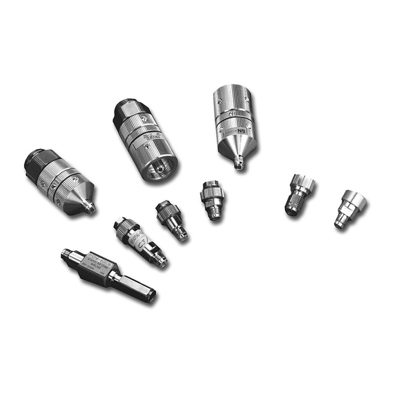
Keysight 3.5 mm Calibration Kit User’s and Service Guide Replaceable Parts Introduction Table 6-1 lists the replacement part numbers for items included in the 85056A calibration kit and Figure 6-1 Figure 6-2 illustrate each of these items. Table 6-2 lists the replacement part numbers for items not included in the calibration kit that are either required or recommended for successful operation of the kit. - Page 48 2 ft by 4 ft conductive table mat with 15 ft grounding wire 9300-0797 ESD heel strap 9300-1308 Connector Cleaning Supplies Anhydrous isopropyl alcohol (>92% pure) Foam-tipped cleaning swabs 9301-1243 a. Keysight can no longer safely ship isopropyl alcohol, so customers should purchase it locally. Keysight 85056A User’s and Service Guide...
- Page 49 Replaceable Parts Introduction Figure 6-1 Replaceable Parts for the 85056A Calibration Kit Keysight 85056A User’s and Service Guide...
- Page 50 Replaceable Parts Introduction Figure 6-2 Replaceable Parts for the 85056A Calibration Kit Keysight 85056A User’s and Service Guide...
-
Page 51: A:.standard Definitions
Calibration Kit Definitions Web page at https://www.keysight.com/us/en/assets/9922-01521/technical-specificatio ns/Calibration-Kit-Definitions.pdf. For a detailed discussion of calibration kits, refer to the Keysight Application Note, “Specifying Calibration Standards and Kits for Keysight Vector Network Analyzers.” This application note covers calibration standard definitions, calibration kit content and its structure requirements for Keysight vector network analyzers. - Page 52 Standard Definitions Class Assignments and Standard Definitions Values are Available on the Web A -2 Keysight 85056A User’s and Service Guide...
- Page 53 Keysight Application , 3–8, 3–9, 3–12 3–2 what to do Note gaging 1–3 A–1 , 3–8, 3–9 damaged connectors modifying definition files determine 3–2 A–1 data overview depth 1–1 3–8 recertification performance 4–2 Keysight 85052A User’s and Service Guide I–1...
- Page 54 6–2 nitrogen precautions 3–4 for cleaning 3–4 protection 3–1 numbers Keysight Technologies supplies replaceable parts 6–1 application note part numbers A–1 6–2 serial 1–4 contacting wrist strap 5–2 recording 1–4 part number 6–2 I–2 Keysight 85052A User’s and Service Guide...
- Page 55 2–1 specifications preventive maintenance 2–4 1–6 specifications 2–1 sliding ring protrusion operating 2–1 sliding load pin depth 3–21 2–2 storage 2–1 specifications 2–1 verification and certification of 2–5 measurement 2–1 terminology, connector 1–6 Keysight 85052A User’s and Service Guide I–3...
- Page 56 7 mm open-end part number 6–2 open-end , 1–3, 3–18, 3–20 proper positioning of 3–18 torque , 1–3, 3–17, 3–18 part number 6–2 precautions 3–18 proper use of 3–18 wrist strap part number 6–2 I–4 Keysight 85052A User’s and Service Guide...
- Page 57 Installation Note Xxxxx-xxxxx...
- Page 58 This information is subject to change without notice. © Keysight Technologies 1996 - 2023 June 2023 85052-90077 www.keysight.com...
Need help?
Do you have a question about the 85056A and is the answer not in the manual?
Questions and answers