Table of Contents
Advertisement
Quick Links
Advertisement
Table of Contents
Troubleshooting

Related Manuals for Intuis Edel AIR


Summary of Contents for Intuis Edel AIR
- Page 1 Edel AIR Domestic hot water heat pump 100 and 150 litres wall mounted Air intake and exhaust using a Ø80/125 concentric duct Installation manual Edel 100 AIR Ref. 353210 Edel 150 AIR Ref. 353211 Made in France Manual ref. : 1898153...
-
Page 2: Table Of Contents
TABLE OF CONTENTS 1-SAFETY ............. 4 6 - SET-UP AND USE .......... 26 6.1 - Control panel ..................26 2 - RECOMMENDATIONS ........6 6.2 - Setting the language ................26 2.1 - Storage ....................6 6.3 - Setting the date and time ...............26 2.2 - Transport ....................6 6.4 - Setting the desired water temperature ........27 2.3 - Manutention ..................7... - Page 3 8 - WARRANTY ........... 41 8.1 - Limitations of warranty..............41 8.1.1 - General information ....................41 8.1.2 -Cases for exclusion from warranty (not limited to) ........41 8.1.2.1 - Use .......................41 8.1.2.2 - Handling ....................41 8.1.2.3 - Installation site ..................41 8.1.2.4 - Electrical connections ................41 8.1.2.5 - Hydraulic connections .................41 8.1.2.6 - Accessories ....................41 8.1.2.7 - Maintenance ....................41...
-
Page 4: 1-Safety
Preserving these documents • Follow all relevant national and international health and safety rules and regulations. This manual and all other relevant documents should be given to the system user. Danger resulting from improper use The system usre should keep these manuals for future reference. Any work carried out by an unqualifi ed person can result in damage to the installation or in 1-SAFETY... - Page 5 A method of disconnection ensuring a Maintenance - Troubleshooting complete cut-off according to Category III • Drainage: Turn off the power supply and the conditions must be installed on the fixed cold water supply, open the hot water valves piping to conform to installation regulations. and then set the safety group to the drainage Protect the appliance with: position.
-
Page 6: Recommendations
2 - RECOMMENDATIONS guarantee damage caused by a transport or handling of the appliance that is not in accordance with our recommendations. • The appliance can only function when fi lled with water. Never turn on the appliance if the tank has not been properly Transporting the appliance in a horizontal fi lled with water and completely purged of air. -
Page 7: Manutention
2.6 - Symbols used 2.3 - Manutention To transport the appliance to the installation location, use the wall bracket and lower handles. ADMISSIBLE transportation positions : Caution : contains Consult the installation Contains regulated manual before all work a fl ammable refrigerant substances, do not dispose fl uid. -
Page 8: Operating Principle
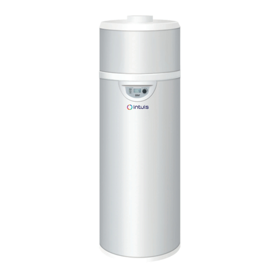
3 - OPERATING PRINCIPLE 4 - INTRODUCTION The domestic hot water heat pump is a small-capacity heat pump 4.1 - Dimensions dedicated to the production of domestic hot water. The appliance uses the air for the capture of calories and then the bonuses to the water of the tank. -
Page 9: Technical Characteristics And Performances
4.2 - Technical characteristics and 4.3 - EU declaration Performances This device complies with international electrical safety standards IEC 60335-1, IEC 60335-2-21, IEC 60335-2-40. The CE marking present on the device attests to its conformity with the Domestic hot water heat pump model 100L AIR 150L AIR following Community Directives, of which it meets the essential... -
Page 10: Installation
5 - INSTALLATION 5.1- Set-up 5.1.1- Installation site INSTALLATION PRECAUTIONS: • The appliance must not be installed near a perpetual fl ame or other source of ignition. • The appliance must be installed in such a way as to prevent mechanical damage to the appliance. -
Page 11: Wall Mounting
5.1.4 - Wall mounting * In the case of assembly with horizontal air ducts or with Ø80mm PVC pipe (with direct outlet at the back) For a durable and per fec tly ver tical Ø132mm a n c h o r i n g , i t i s drilling recommended to use axes for the... -
Page 12: Options
5.1.5 - Options 5.1.5.2 - Wall fastening brackets 5.1.5.1 - Tripod for on-ground installation Tripod with adjustable height from 300 to For the 100 l ref: 730017 x1 515mm For the 150 l ref: 730018 x2 5.2 - Air connections The domestic hot water heat pump can recover calories from exterior air or ambient air from unheated premises due to its horizontal Ø80/125 concentric air duct. -
Page 13: 1- Air Intake And Exhaust In Unheated Premises
5.2.1.2- Exterior air exhaust using Ø80 PVC 5.2.1- Air intake and exhaust in unheated pipe premises (20m minimum) insulated from neighbouring heated rooms A < 10m (1 extra elbow equivalent to 1m) If insulation of heated adjoining rooms is insuffi cient, loss of heat is more likely. 5.2.1.1 - In the same room as the appliance Description Rep. -
Page 14: In An Adjoining Room, With Vertical Air Ducts
5.2.1.4 - In an adjoining room, with vertical air ducts Min. cutting height for the Ø125 X + D < 5m insulated elbow (rep.a1)= 220mm • Height of dimension «D»: - if D = 350mm, use the insulated Ø80/125 air duct elbow rep.a1 ) without cutting it again. -
Page 15: Installing With Lateral Air Ducts
rep.f X + 25 mm • Cut the Ø125 PVC pipe ( ) to ( Rep. Description • Glue the pipe into the air duct nozzle. Rear or vertical insulated air duct Ø80/125 - 355mm long • Position the Ø125 wall joint. (air duct nozzle + Ø125 wall joint + F155/F125 wall flange + •... -
Page 16: Installing With Lateral Air Ducts
rep.f • Cut the Ø125 PVC pipe ( ) to (X + 25mm). Rep. Description • Glue it into the air duct nozzle. Rear or vertical insulated air duct Ø80/125 - 355mm • Position the Ø125 wall joint. long • Pass the assembled air duct nozzle through the wall from the outside. (air duct nozzle + Ø125 wall joint + F155/F125 wall •... -
Page 17: Installation With Lateral Air Ducts And Elbow Outlet
- Remove the cover parts from the fi rst insulated elbow 5.2.2.4 - Installation with lateral air ducts and - Insert the fi rst Ø80 PVC elbow into the base of the fi rst insulated elbow outlet elbow and fi x it to the Ø80 PVC pipe (apply a bit of silicone so that A + B + X <... -
Page 18: Installation With Lateral Ducts At Distance "C" Above The
• FOR PART «C»: 5.2.2.5 - Installation with lateral ducts at - Remove the Ø80 PVC pipe (lg 140mm) located on the appliance’s distance «C» above the appliance air outlet. rep.e - Cut the second Ø80 PVC pipe ( ) to (C-65mm) A <... - Page 19 • Position the Ø125 PVC pipe through the ceiling and insulation, as well as the two F155/F125 fl ange rings, one placed on the inside and one on the outside. Do not glue the two F155/F125 fl ange rings onto the Ø125 PVC pipe. •...
-
Page 20: 3- Piping Accessories
5.2.3- Piping accessories 5.2.3.1 - For air duct connection onto ambient or exterior air Ø80/125 Insulated elbow kit for air duct includes: Ø125 insulated elbow + parts for insulated elbow + Ø80 F/F PVC elbow Ø80/125 Insulated elbow kit for air duct includes: Ø125 insulated elbow + parts for insulated elbow + Ø80 F/F PVC elbow PVC e... -
Page 21: Hydraulic Connections
5.3 - Hydraulic connections • A new pressure-relief valve (not included) must be installed and set to 6 bars on the domestic cold water supply of the appliance. The use of a membrane valve is recommended. This valve must conform to all local and national standards. •... - Page 22 Condensate drainage hose To drainage Domestic Hot Water (DHW) Domestic Cold Water (DCW) Stop valve* Run-off siphon* Pressure-reducing valve* Expansion vessel* Check valve* Thermostatic mixing valve* Dielectric fi ttings (supplied) Drainage valve* Pressure-relief membrane valve* 10. Condensates drainage * not supplied DOMESTIC HOT WATER HEAT PUMP 100L &...
-
Page 23: Condensates Drainage
5.4 - Condensates drainage The cooling of the air circulating in the evaporator can lead to the formation of condensate, the quantity of which varies according to the level of humidity in the air. Condensate must be evacuated via a drain pipe at the rear of the appliance to a waste water drain. To ensure correct drainage, the following points must be observed: •... -
Page 24: Electrical Connections
• Remove the protective casing. 5.5 - Electrical connections • Remove the black cover from the electronics board. • Pass a 0.75mm² 2-wire cable with metal tips through a cable gland at the back of the appliance and bring the end of the cable around Do not connect the Domestic hot water to the electronics board. -
Page 25: Connection To The Pv Function
5.5.1.4 - Connection to the PV function This function enables the appliance to operate in auto-production mode, which means that it will use the energy produced by the PV function to supply the heat pump as well as the electrical back-up, and to heat the water in the tank. The connection is made between the energy manager electrical box (not supplied) and connectors 1 and 2 on the electronics board. -
Page 26: Set-Up And Use
6 - SET-UP AND USE 6.2 - Setting the language Deterioration risk : the hot water tank must be fi lled with water before it is When the appliance is turned on for the fi rst time, the language must switched on or connected to a power be selected. -
Page 27: Setting The Desired Water Temperature
• Press to return to the main menu. 6.4 - Setting the desired water The settings are available according to the following reasoning: temperature ≤ ≤ ≤ TEMP T° PV ECO T° PV MAX 65°C 6.4.1 - PV mode not activated Target water temperature used by T °P V E CO The water temperature can be adjusted from 30°C to 65°C. -
Page 28: Electric Mode
6.7 - Electric mode (for operation using only the electrical back-up) e le c m ode « » uses only the electrical back-up to heat the water in the Domestic hot water heat pump. It provides a back-up option if for any reason the heat pump is not operational (piping not connected, dusty renovation work being carried out near the appliance, etc...). -
Page 29: Installer Menu
7. Turn the dial to select the primary function: 6.9 - INSTALLER menu - Menu → INST. MENU → PV MODE → PRIORITY It may be necessary to adjust certain settings to optimise the • Yes: the signals from connectors 1 and 2 take precedence over eco and frost protection modes. -
Page 30: Fan Mode -Fan Mode
If the load shedding switch is on: • If the desired water temperature is set at 60°C, (see § «Setting the desired water temperature»), there will not be an anti-legionellosis Mode 0 = No element is authorised to operate. cycle as it is already running continuously. Mode 1 •... -
Page 31: Resetting Parameters
AUTO = Lock menu access with temporary unlocking (60 seconds), 6.9.5 - Reading data press for 3 seconds. The «READ DATA» menu shows you, in real time, the information given by the sensors. Go to the «Installer» menu, turn the dial to «display». u nlo ck Display Description... -
Page 32: Maintenance And Troubleshooting
7 - MAINTENANCE AND .../... TROUBLESHOOTING → In case of intervention on the refrigerant circuit: In order to maintain effi ciency and improve durability 1) Secure the area you will be working in. it is advised that an annual maintenance check be 2) Inform people of the potential danger carried out by a qualifi ed professional. -
Page 33: Air Intake Circuit
7.2 - Air intake circuit 7.6 - Decommissioning The only maintenance work needed on the air intake circuit is to 7.6.1 - Leak detection clean the evaporator (at least once per year and dependent on the In the event of a prolonged absence with the power supply to the quality of air intake). -
Page 34: Charging Process
7.6.3 - Charging process 7.6.5 - Recovery • Ensure that contamination of diff erent refrigerants does not occur When transferring refrigerant into the recovery bottles, ensure that when using charging equipment. Hoses or lines should be as short only the appropriate bottles are used. Make sure you have enough as possible to minimize the amount of refrigerant they contain. -
Page 35: Troubleshooting
• The tubes do not have bends or «U» shapes that could collect water. 7.7 - Troubleshooting • The tube opens into an open-air duct. • The appliance is properly positioned (vertical position and no • No hot water tilting). Check that: •... -
Page 36: Ntc Sensor Data
If the current is >0.3mA, the anode is operational, if the current • Unscrew the screw and the insulating ring holding the heating <0.3mA check the anode visually. element in place. To access the anode, the heating element, and to clean the tank: •... -
Page 37: List Of Spare Parts
7.10 - List of spare parts DOMESTIC HOT WATER HEAT PUMP 100L & 150L AIR INSTALLATION MANUAL... - Page 38 100L 150L Description Regulation / Display B1244096 B1244096 Electronic circuit board controller Circuit board + display +H2P program - CET B4992816 B4992816 B4992653 B4992653 Display screen cable - 480mm + foam B1244576 B1244576 Temperature sensor lg460mm B1244577 Temperature sensor lg700mm B1244575 Temperature sensor lg1200mm B4993072...
-
Page 39: Error Message Codes : Errors, Solutions, And Operating In Case Of Error
7.11 - Error message codes : errors, solutions, and operating in case of error Note: Errors can be dismissed by briefl y pressing the dial (manual reset) Temporary operation measures Display Error Probable causes Solutions while waiting for the problem to be solved •Voltage too high on electrical network... - Page 40 Temporary operation measures Display Error Probable causes Solutions while waiting for the problem to be solved •The air and defrosting sensors are reversed on the circuit board •The defrosting and water sensors are reversed on the circuit board •Reposition temperature •Incorrect temperature sensor •The defrosting...
- Page 41 8 - WARRANTY 8.1.2.2 - Handling Cases (not limited to) where the warranty is void: • Any damage sustained by impacts or falls during handling after The tank is guaranteed against breakage for a period of five (5) delivery from the factory. years, starting from the date the appliance was activated, if the •...
- Page 42 9 - APPENDICES 9.1 - Electrical wiring diagram C1 - Fan capacitor Compressor VD - Defrosting valve RE - Electrical resistance 1200W LTS - Heat-limiting safety thermostat for the electrical back-up AqL - Electrical back-up aquastat HP - High pressure pressure sensor DOMESTIC HOT WATER HEAT PUMP 100L &...
- Page 43 DOMESTIC HOT WATER HEAT PUMP 100L & 150L AIR INSTALLATION MANUAL...
- Page 44 • Switch off the heat pump water heater before opening it. • Wait for the fan to come to a complete stop before undertaking any work on the appliance. www.intuis.fr Industrial and development site Rue de la République CS 40029 80210 Feuquières-en-Vimeu...
Need help?
Do you have a question about the Edel AIR and is the answer not in the manual?
Questions and answers