Table of Contents
Advertisement
Quick Links
Advertisement
Table of Contents

Related Manuals for MP Filtri ICM


Summary of Contents for MP Filtri ICM
- Page 2 Inline Contamination Monitor User Guide www.mpfiltri.co.uk 200.000-EN...
- Page 3 Covers All ICM Models except -AZ2 (ATEX) Safety Warning Hydraulic systems contain dangerous fluids at high pressures and temperatures. Installation, servicing and adjustment is only to be performed by qualified personnel. Do not tamper with this device. Document Revision 0.26...
-
Page 4: Table Of Contents
Contents Introduction • Operating Principle How to Order • Related Products Specification • • • • • Performance Hydraulic Environmental Physical Electrical • Warranty and Recalibration Status LED Front Panel Operation • • Result Display Diagnostics Display Water Sensor Data Logger Remote Display Unit Option USBi Optional Computer USB Interface 10 Remote Control... - Page 5 12 Settings • • • • • General Test Number Test Duration Test Format Flow • • Indication Continuous Testing Alarms 13 Installation • Installation Procedure 14 Electrical Interface • • • • DC Power Serial Interface Switched Input and Output Signals Start •...
- Page 6 Recommendations Hydraulic System Target Cleanliness Levels New ISO Medium Test Dust and its effect on ISO Contamination Control Standards • • • • Calibration New Test Dust Benefits Effect on Industry Correlation • Other Standards Clean working practises...
-
Page 8: Introduction
The graphical LCD and keypad allow direct local display of the re- sults in any selected format. ICM-W models also perform a measurement of % saturation of Wa- ter in oil (RH), and fluid temperature (°C). 1.1 Operating Principle The instrument uses a light extinction principle whereby a specially collimated precision LED light source shines through the fluid and... -
Page 9: How To Order
Example: Common Features – All versions can be controlled by a PC, PLC or the ICM-RDU Remote Display Unit. Included is time- stamped data-logging for around 4000 tests, an integral status LED to in- dicate fault conditions, RS485 communications and measurement in multiple international standard formats. -
Page 10: Related Products
This is a ready-made solution for easily connecting a computer to the ICM. Figure 2 USBi It comprises a USB:RS485 interface with a terminal block pre-wired with the ICM cable. An extra terminal block is provided for any How to Order... - Page 11 customer wiring to external devices. An external DC adapter can be used to power the complete system, or if the computer is always connected during use, power can be taken directly from the USB cable. Full usage instructions are provided in the separate product user guide.
-
Page 12: Specification
AS4059 Rev.E. Table 2 Sizes A-F : 000 to 12 Lower Limits are Test Time dependent. If system above 22/21/18 or approx. NAS 12 a coarse screen filter should be fitted to prevent blockage. This is available from MP Filtri UK Part SK0040. Reporting Formats ISO 4406:1999 NAS1638... - Page 13 Differential (Inlet-Outlet) Typically 0.5 bar, but see section 15.1. Pressure Seal Material Viton. Contact MP Filtri UK for any fluids that are incompatible with Viton seals. 3.3 Environmental Ambient Temperature -25 to + 80 °C for non K version, -25 to + 55°C for K...
-
Page 14: Warranty And Recalibration
The ICM is guaranteed for 12 months from date of receipt. Re-calibration The ICM is recommended to be recalibrated every 12 months. Return to MP Filtri UK for recalibration. As a policy of continual improvement, MP Filtri UK reserve the right to alter the specification without prior notice. Specification... -
Page 15: Status Led
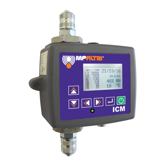
4 Status LED All ICM versions have a multicolour indicator on the front panel, which is used to indicate the status or alarm state. The alarm thresh- olds can be set from LPA-View via the serial interface. ICM-K Figure 1 Front Panel Versions Green indicates that the test result passed, i.e. - Page 16 Violet indicates that the upper temperature limit was exceeded. The LED can also indicate various fault codes by turning red and flashing white a number of times, see section 16.1. This alarm, if set, takes priority over the Contamination and Water alarms. In the event of an over-temperature condition, the LED will turn violet only, whether or not there is also a contamination or water alarm condition.
-
Page 17: Front Panel Operation
5 Front Panel Operation 5.1 Result Display ICM-K models have a 6 button keypad and a small graphical LCD. This allows the display of the test result (current cleanliness level, with water content and temperature if applicable). Figure 1 The graphical format allows a full display of all codes of the stan- dards supported. - Page 18 Simple Detailed Figure 2 ISO4406:1999 Simple Detailed Figure 3 NAS1638 Simple Detailed Figure 4 AS4059E Table 2 Front Panel Operation...
- Page 19 Simple Detailed Figure 5 AS4059E Table 1 Simple Detailed Figure 6 ISO11218 (Draft) 5.2 Diagnostics Display Press < to show the diagnostics displays (used when diagnosing problems). Then switch between the diagnostics screens using the ▲ and ▼ buttons. Completion shows a number from 0 to 1000, indicating the test progress. FLOW ml/min provides an approximate indication of flow rate, up- dated after each test.
- Page 20 The third screen shows diagnostics related to CAN bus communica- tions. For more details refer to the separate ICM CAN bus manual. These correspond to the front panel LED fault codes. Front Panel Operation...
-
Page 21: Water Sensor
6 Water Sensor ICM-W models measure water content using a capacitive RH (rela- tive humidity) sensor. The result is expressed as percentage satura- tion. 100% RH corresponds to the point at which free water exists in the fluid, i.e. the fluid is no longer able to hold the water in a dissolved solution. - Page 22 2 Bar 100 Bar 200 Bar 400 Bar Actual RH Figure 1 Water Sensor Response variation with Absolute Pressure Water Sensor...
-
Page 23: Data Logger
7 Data Logger The ICM includes a built-in data logger, which adds the facility to log and timestamp test results locally within an internal memory, even when not connected to a computer. • Tests that are logged, and when, are determined by the log set- tings (see section 12.6). -
Page 24: Remote Display Unit Option
ICM, change settings or download results, without having to unplug the RDU. The same components are used for the RDU as for the normal ICM -K option, so the same instructions apply for operation. See chap- ter 5 for more details. -
Page 25: Usbi Optional Computer Usb Interface
Figure 1 ICM-USBi: A USB Interface Unit for the ICM This is a ready-made solution for easily connecting a computer to the ICM. It comprises a USB:RS485 interface with a terminal block pre-wired with the ICM cable. An extra terminal block is provided for any customer wiring to external devices. -
Page 26: Remote Control
10 Remote Control The ICM can be controlled using the remote control facility included in the LPA-View software package, installed on a PC. Alternatively customers can use their own software running on a PC or PLC. Since the ICM includes a built-in datalogging memory, operators can make use of the remote control facility in one of two ways: •... - Page 27 • All working communication ports of the computer are available for selection. Select the one used to connect the ICM, then press OK. If you are unsure which port is correct, the device name should be next to the COM port number.
- Page 28 has been established successfully, the remote control dialogue will appear. After a successful connection, the COM port will be remembered for next time and will appear preselected in the dialogue. Remote Control...
-
Page 29: Pc Software Operation
11 PC Software Operation The Remote Control dialogue allows an operator to manually con- trol the ICM from a PC, using the LPA-View software. It can also be used to download test results that have accumulated during au- tonomous (disconnected) operation. - Page 30 Download All buttons. The difference between these is that Down- load New only transfers results that have never been downloaded before. Download All transfers all results that are stored in the ICM. Erase Log deletes the test results from the memory of the ICM.
- Page 31 The calibration area displays the date last Calibrated and the next Calibration Due date. The ICM has been designed to be a very flexible product, so has a wide range of settings and operating modes. However the shipped defaults are suitable for most applications and many users can skip this section.
- Page 32 12.2 Test Number The Test Number can be used to help identify a test within a se- quence. However it is automatically reset when the ICM is powered up, so instead relying on the timestamp (date and time of test) and test reference is preferred.
- Page 33 12.5 Flow Indication • The ICM uses the width of the pulse to derive flow, its flow out- put is only an indication, intended for installation guidance. • It is worth reinforcing that the primary function of the product is to produce a measurement of cleanliness, and not act as a flow...
- Page 34 (for example zero) results in a new test being started immediately a test finishes. Start Testing Automatically sets the ICM to begin a test soon after it is powered up. This is ideal for unattended systems. Stop Testing When Clean is a feature intended for cleaning rigs or "filter trolley’’...
- Page 35 12.7 Alarms The ICM has two switched "alarm’’ outputs that can be used to sig- nal external equipment in various ways, according to the test results and the alarm settings. There is also a multi- colour front panel light which indicates how the result compares to the set alarm thresholds.
- Page 36 In general there are upper and lower limits that can be set for the cleanliness level, also for water content and temperature if applica- ble. An alarm, if enabled, will become active if any of the associated (upper/lower) limits are exceeded. However if a field is left empty (blank) this is interpreted as a "don’t care’’...
- Page 37 this being the highest of the individual codes generated for each de- fined particle size. Hence we have the option of setting a limit on this overall contamination class (the Basic Class), or we can set individ- ual limits on any combination of the classes for the defined particle size ranges.
- Page 38 Intended Function Warning Alarm This allows the ICM to switch external warning lights or alarms. Output 1 is the "Warning’’ output, switching on if any of the Lower Note that these outputs are distinct from the front panel LED, and that the set alarm mode does not affect the LED.
- Page 39 limits are exceeded. Output 2 is the "Alarm’’ output, behaving sim- ilarly for the upper limit. Alarm Mode 1: Clean-Dirty Output 1 Output 2 Turns on When ≤Lower >Upper Intended Function Clean Dirty This could be used in a cleaning system that attempts to maintain a cleanliness level by switching a pump on and off.
- Page 40 on when the result is less that the upper limit. Output 2 ("Red’’) is turned on when the result is greater than the lower limit. If the result is in between, both outputs are turned on and the LED colour will be amber (i.e.
- Page 41 This is used when controlling tests from a PLC using switched out- puts. The PLC gives a start signal, then monitors the "Test Com- plete’’ output. If the test has passed it can detect this with the "Pass’’ signal. Alarm Mode 6... Customer Requested Modes Other alarm modes will be defined as and when customers request them.
- Page 42 flowing upwards through it. • Wire back to junction box. • Check flow in acceptable range. There needs to be a differen- tial pressure placed across the ICM, such that a flow of fluid is generated within the range of the unit. Installation...
- Page 43 Any pressure pulsations (for example from a pump) in the feed to the ICM are then translated into pulsations in flow rate, sometimes leading to flow reversals in time with the pulsations. If the flow is very low this can sweep the same particle backwards and forwards through the sensing volume multiple times, confusing the results.
- Page 44 14 Electrical Interface Note: The separate ICM-USBi product is available for those wishing to simply plug the ICM into a computer. This section is for those wishing to do their own wiring to the product. Figure 1 External Wiring Example In Figure an example installation is shown.
- Page 45 14.1 DC Power DC power is connected to pins 7 and 8 of the ICM circular connector (Red and Blue if using the pre-wired cable). All the other signals are optional. Item Minimum Maximum Voltage 9V DC 36V DC Current 200mA 14.2 Serial Interface...
- Page 46 3m cable available for the ICM would be used, with a junction box to connect to the RS485 trunk. Either individual DC supplies can be used to power each ICM, or a single supply run through the trunk cable. Figure 4 shows how to connect the ICM-RDU Remote Display Unit.
- Page 47 The RS485 interface is more flexible but requires more software work if LPA-View is not used (e.g. control from a PLC). An alternative is to control the ICM via these switched signals, either from a PLC or using a manual switch and indicators.
- Page 48 Figure 5 Switched I/O Signals Item Minimum Maximum Voltage 9V DC 36V DC Impedance 10k Ohms Other ways to start a test are: • Via LPA-View or PLC Modbus command. • Periodic automatic testing according to a programmed test mode. 14.5 Alarm Outputs These are opto-isolated switches that can be used to signal external indicators, PLC inputs or other equipment (e.g.
- Page 49 The exact function of these outputs is determined by the Alarm Mode setting (see 12.7.3). The outputs are "voltage free’’ contacts that can switch AC or DC signals up to 36V nominal (60V absolute maximum peak voltage). Item Minimum Maximum Voltage 36V DC Current...
- Page 50 15 Hydraulic Connection 1 High or Low Pressure Parallel Connection Figure 1 ICM working pressure generated by hydraulic component. 2 Low Pressure, Off-Line Operation Figure 2 ICM working pressure gen- erated by hydraulic component. 3 Very Low Flow Systems Figure 3 Entire system flow rate is within the range of the ICM.
- Page 51 15.1.2 Detailed Calculations In general the flow rate of fluid through the ICM needs to be kept within the range of the unit (see hydraulic specification 3.2). The ICM measures the flow during operation, so this can be used to check that the flow is correct.
- Page 52 (So in this case the pressure-flow relationship is mainly depen- dent on hose resistance.) • Add the ICM pressure drop to that of the hoses, e.g. 4 + 0.4 = 4.4 Bar. When the required pressure drop has been found:...
- Page 53 Of course in a real system the pressure and viscosity will vary with temperature and operating conditions. But since the work- ing flow range of the ICM is very wide, this should not be a prob- lem provided it remains within range. On the graph the area be- tween upper and lower lines represents the usable operating re- gion for the ICM, with the middle line being ideal.
- Page 54 • The flow controller must be fitted to the outlet only. If fitted to the inlet it will have a filtering effect. • The flow controller must be fitted directly to the ICM outlet port. Hydraulic Connection...
- Page 55 This is only needed for High Pressure, Off-Line Operation. Figure 5 ICM flow actively regulated. A pressure compensated flow control valve is fitted to the ICM drain outlet. This maintains a constant flow rate even with a varying inlet pressure (provided this pressure stays above a minimum working value).
- Page 56 16 Fault Finding 16.1 LED Flashing / Fault Codes The ICM front panel led indicates a fault by a number of white flashes, with a red background. The number of flashes indicates the fault code: 1. Optical - An optical fault could indicate LED failure or blockage of the optical path.
- Page 57 ICM operation, if desired, allowing more specific diagnostics. Value Function Comment NOT READY Unit is powering-up, or there is some problem READY Ready to start a test TESTING Test in progress WAITING Waiting between tests...
- Page 58 flush with a suitable solvent may clear the blockage. The standard ICM is fitted with Viton seals, so Petroleum Ether may be used for this purpose, in conjunction with the MP Filtri UK Bottle Sampling Unit.
- Page 59 17 Cycle Time and Flow Rate Considerations The set Test Duration is the amount of time for which particle counts are accumulated, before the test result is updated. The default of 120 seconds is likely to be suitable for most applications. However it is possible to set other values.
- Page 60 1000 400ml/minute (max. flow) 200ml/minute (ideal flow) 20ml/minute (min. flow) ISO Code Figure 1 Test Time needed for Reliable Indication by ISO code Cycle Time and Flow Rate Considerations...
- Page 61 The ICM can be controlled via commands on its serial (RS485) in- terface, using the Modbus RTU protocol. It is possible to control every aspect and setting of the ICM, as is done by the MP Filtri UK LPA-View control software. All results and counts are available in all supported formats.
- Page 62 Appendix A Measuring Water in Hydraulic and Lubricating Fluids From North Notts Fluid Power Centre In mineral oils and non aqueous fire resistant fluids water is undesirable. Min- eral oil usually has a water content of 50-300 ppm which it can support with- out adverse consequences.
- Page 63 Appendix A Typical Water Saturation Levels For New Oils Figure I Examples: Hydraulic oil @ 30°C = 200ppm = 100% saturation Hydraulic oil @ 65°C = 500ppm = 100% saturation Measuring Water Content...
- Page 64 Appendix B ISO4406:1999 Cleanliness Code System The International Standards Orga- nization standard ISO 4406:1999 is the preferred method of quoting the number of solid contaminant par- ticles in a sample. The code is constructed from the combination of three scale numbers selected from the following table.
- Page 65 Appendix B Microscope counting examines the particles differently to APCs and the code is given with two scale numbers only. These are at 5 µm and 15 µm equivalent to the 6 µm(c) and 14 µm(c) of the APCs. ISO4406:1999 Cleanliness Code System...
- Page 66 ICM software. Figure I CONTAMINATION LEVEL CLASSES according to NAS1638 (January 1964).
- Page 67 Contamination Limits (Particles/100ml) of differential and cumula- tive particle counts respectively for counts obtained by an automatic particle counter, e.g. ICM. The information reproduced on this and the previous page is a brief extract from SAE AS4059 Rev.E, revised in May 2005. For further details and explanations refer to the full Standard.
- Page 68 Appendix D Size range μm(c): 6 - 14 14 - 21 21 - 38 38 - 70 >70 Class 1,000 2,000 4,000 8,000 1,425 16,000 2,850 32,000 5.700 1,012 64,000 11,400 2,025 128,000 22,800 4,050 256,000 45,600 8,100 1,440 512,000 91,200 16,200 2,880...
- Page 69 Appendix D Size μm(c) >4 >6 >14 >21 >38 >70 Size Code Classes 1,560 3,120 1,217 6,250 2,432 12,500 4,864 25,000 9,731 1,731 50,000 19,462 3,462 100,000 38,924 6,924 1,224 200,000 77,849 13,849 2,449 400,000 155,698 27,698 4,898 800,000 311,396 55,396 9,796 1,696 11 1,600,000...
- Page 70 Appendix E Recommendations Unit Type ISO 4406:1999 Code PUMP Piston (slow speed, in-line) 22/20/16 Piston (high speed, variable) 17/15/13 Gear 19/17/15 Vane 18/16/14 MOTOR Axial piston 18/16/13 Radial piston 19/17/13 Gear 20/18/15 Vane 19/17/14 VALVE Directional (solenoid) 20/18/15 Pressure control (modulating) 19/17/14 Flow control 19/17/14 Check valve...
- Page 71 Appendix E fluids which are cleaner than those stated will increase life. However, the di- versity of hydraulic systems in terms of pressure, duty cycles, environments, lubrication required, contaminant types, etc, makes it almost impossible to predict the components service life over and above that which can be rea- sonably expected.
- Page 72 Appendix F Hydraulic System Target Cleanliness Levels Where a hydraulic system user has been able to check cleanliness levels over a considerable period, the acceptability, or otherwise, of those levels can be verified. Thus if no failures have occurred, the average level measured may well be one which could be made a bench mark.
- Page 73 Appendix F Contamination Corresponding Recommended Typical Codes Codes Filtration Applications ISO 4406:1999 NAS 1638 Degree Bx200 μm(c) μm(c) μm(c) High precision and laboratory servo-sys- tems Robotic and servo-systems 10-12 Very sensitive - high reliability systems 12-15 Sensitive - reliable systems 15-25 General equipment of limited reliability...
- Page 74 Appendix G New ISO Medium Test Dust and its effect on ISO Contamination Control Standards When General Motors gave advance warning to the International Standards Organization (ISO) that it was intending to stop the production of AC Fine Test Dust (ACFTD), work commenced immediately on finding an improved replacement dust.
- Page 75 Appendix G ISO therefore defined the requirements for the replacement for ACFTD and asked the National Institute of Standards and Technology (NIST) in the USA to produce a standard, traceable reference material. The new dust’s parti- cle size distribution has been accurately determined with the aid of modern scanning electron microscope and image analysis techniques.
- Page 76 Appendix G The standards affected include: ISO 4402:1991 Hydraulic fluid power Calibration of liquid automatic particle counters. ISO 4406:1987 Hydraulic fluid power Code for defining the level of contamination by solid par- ticles. ISO 4572:1981 Hydraulic fluid power – Filters Multi-pass method for evaluating filtration performance of a filter element.
- Page 77 The following charts shows the correlation between the old ACFTD and the new ISO MTD. The ICM is calibrated with ISO Medium Test Dust (to ISO 11171). The correlation between particle sizes and the ACFTD (old standard) to the ISO MTD (new standard) is as follows : ACFTD <1 5 15 25 30 50...
- Page 78 Appendix G Particle Size Obtained Using Correlation ACFTD ISO/NIST (ISO (ISO 11171) 4402:1991) The table shows the correla- µm µm(c) tion between Particle Sizes Obtained using ACFTD (ISO 4402:1991) and NIST (ISO 11171) Calibration Methods This table is only a guideline. 10.6 11.3 The exact relationship between...
- Page 79 Appendix G Other Standards Although the ISO 4406:1999 standard is being used extensively within the hydraulics industry other standards are occasionally required and a compar- ison may be requested. The following table gives a very general comparison but often no direct comparison is possible due to the different classes and sizes involved.
- Page 80 Appendix G ISO 4406:1999 DEF.STD 05/42 [7] NAS 1638[5] SAE 749[8] Table A Table B ISO 11218[6] 13/11/08 14/12/09 15/13/10 16/14/09 400F 16/14/11 17/15/09 17/15/10 800F 17/15/12 18/16/10 18/16/11 1,300F 18/16/13 19/17/11 1,300 2000F 19/17/14 20/18/12 2,000 20/18/13 4,400F 20/18/15 21/19/13 4,400 6,300F...
- Page 81 Appendix H Clean working practises The majority of hydraulic systems require cleanliness which controls below around a 40 micron threshold (beyond the limit of human eyesight). When analysing particles down to levels of 4um, 6um & 14um you are talking about objects of a cellular/bacterial size.
- Page 82 Appendix H • Do perform a statistically large enough sample of particle analysis results ( 25) to arrive at a base cleanliness level for your system. • Do make sure that filters are correctly sized for your applications and cleanliness you are trying to achieve. Don’ts •...
- Page 83 Appendix H Clean working practises...
- Page 84 Produced by MP Filtri UK Revision 0.26 As a policy of continual improvement, MP Filtri UK reserve the right to alter specifi- cations without prior notice. Except as permitted by such licence, no part of this publication may be reproduced, stored in retrieval system or transmitted, in any form or any means, electronic, me- chanical, recording, or otherwise, without prior written permission of MP Filtri UK.
- Page 85 Fax: +1.905-303-7256 Email: s.mishra@mpfiltri.com Email: mail@mpfiltricanada.com Website: www.mpfiltri.com Website: www.mpfiltricanada.com RUSSIAN FEDERATION CHINA MP FILTRI RUSSIA INC MP FILTRI (Shanghai) Co Ltd Phone mobile: +7.095-502-5411 Tel: +86.21-58919916 Fax: +7.095-205-9410 Fax: + 86.21-58919667 Email: mpfiltrirussia@yahoo.com Email: sales@mpfiltrishanghai.com Website: www.mpfiltri.ru Website: www.mpfiltrichina.com GERMANY MP FILTRI USA Inc.
Need help?
Do you have a question about the ICM and is the answer not in the manual?
Questions and answers