Table of Contents
Advertisement
Quick Links
Advertisement
Table of Contents

Related Manuals for MP Filtri CML2


Summary of Contents for MP Filtri CML2
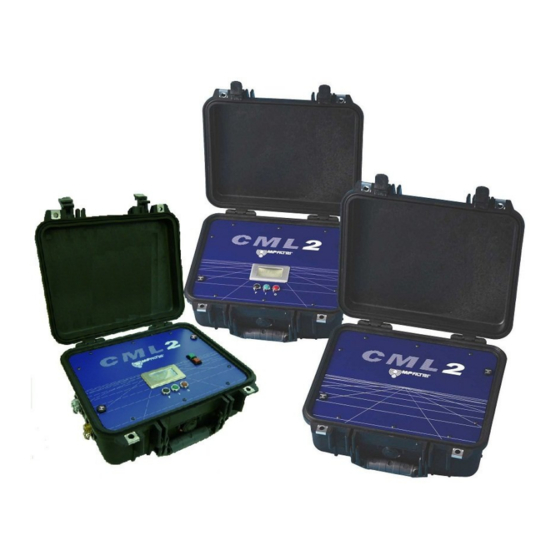
- Page 1 CML2 Analyser User Guide www.mpfiltri.com 200.051-EN...
- Page 2 Covers Model Numbers CML2 SAFETY WARNING Hydraulic systems contain dangerous fluids at high pressures and temperatures. Installation, servicing and adjustment is only to be performed by qualified personnel. Do not tamper with this device. Document Revision 4.1...
-
Page 3: Table Of Contents
USB Port • • • Operating the CML2 Settings Normal Test • • CML2 without Moisture Sensor CML2-W with Moisture Sensor Continuous Sampling • • Continuous Test Basic Operation With Moisture Sensor Moisture Sensor 10 Bottle Sampling 11 Battery Charging (series 41 only) - Page 4 12 Warranty • Recalibration Measuring Water in Hydraulic and Lubricating Fluids ISO4406:1999 Cleanliness Code System NAS1638 Cleanliness Code System SAE AS4059 REV.E Cleanliness Classification For Hydraulic Fluids Recommendations Hydraulic System Target Cleanliness Levels New ISO Medium Test Dust and its effect on ISO Contamination Control Standards •...
-
Page 5: Precautions
1 Precautions 1.1 Internal Cleaning clean the CML2 or Bottle Sampler with Acetone or similar solvents that are not compatible with the seal. For flushing fluids please see the website: www.mpfiltri.co.uk The use of a 500μm coarse screen filter, screwed onto the HP con- nector, is recommended for heavily contaminated system. -
Page 6: Introduction
2 Introduction The CML2 is designed to measure and quantify the numbers of solid contaminants in Hydraulic, Lubrication and Transmission applica- tions. The CML2 is a portable, accurate, instrument suitable for laboratory or "on-site" applications utilising mineral oil as the op- erating fluid. - Page 7 within the system and it is these levels of contaminants that the par- ticle counter is designed to measure. ISO Cleanliness Code – The international standard for reporting solid contami- nants is ISO4406: 1999, this standard has been revised to incorporate the change to ISO Medium Test Dust as the calibration standard.
- Page 8 Figure 1 Series 35 Key Diagram Introduction...
- Page 9 Figure 2 Series 40 Key Diagram Introduction...
- Page 10 Figure 3 Series 41 Key Diagram Introduction...
-
Page 11: Scope Of Supply
• 500 µm coarse screen filter • External Battery Pack See page 66 for more details. This is a dedicated unit for the CML2 and should not be used with other MP Filtri UK products, especially the 12V Bottle Sampler Units. Scope of Supply... -
Page 12: Connection
2. Connect waste fluid hose to CML2 (waste connector). Push back quick coupling outer ring before connecting / disconnecting hose end. -
Page 13: Methods Of Operation
6. Installing LPA-View software – refer to the LPA-View User Manual and follow the CD Installation instructions. 7. Connect serial cable into the CML2 RS232 connector and the other end into a PC. If the PC has only USB ports, use the USB to serial converter and follow the instructions on page 22. -
Page 14: Pushbutton Operation
5 Pushbutton Operation This mode of operation is the most straightforward way to use the CML2, as the three principal operations of opening/closing the flush valve, starting a test and stopping a test can be readily performed using the pushbuttons. - Page 15 ’low battery’ warning - this will illuminate ’red’ if the battery has insufficient power. RED - Switches CML2 unit off: Note; the in-built LED is used to display a ’unit charging’ warning - this will illuminate ’red’ if the mains supply is connected.
-
Page 16: Using The Pushbuttons
Follow the actions below to perform a Normal test: • Press Flush Pushbutton (F) This will open the flush valve to allow fluid to pass through the CML2, so that any fluid from the previous test is flushed out of the Pushbutton Operation... - Page 17 fluid, followed by an emptying cycle during which the 15ml of fluid is discharged to waste. At the end of the emptying cycle the CML2 will come to rest and the test results will be displayed on the LCD screen.
- Page 18 Connect the CML2 to a PC running LPA-View and follow the in- structions given to Transfer Log on page 24. It is important to set the Test Reference (refer to page 25) before...
-
Page 19: Pc Operation
6 PC Operation PC control of the CML2 is performed using the Remote Device Di- alogue included in the LPA-View software package - refer to the separate LPA-View user manual for details of software installation. Users may typically wish to operate the Remote Device Dialogue facility in one of two ways:- •... - Page 20 Figure 1 LPA-View To access the Remote Device facility in LPA-View, press the Remote Control button on the toolbar. The first time that this is done, the correct communications port (COM port) on the computer has to be selected, as detailed below. 1.
- Page 21 2. Press the OK button, when the correct port is chosen, the Remote Device dialogue will show the remote device values. Figure 3 Remote Device dialogue The LPA-View program will remember this selection the next time it is used. 6.2 Determining the COM Port To check the COM port number allocated by the computer for the Serial lead or the USB to Serial Connector: •...
- Page 22 When a built-in computer serial port is not available the USB to serial converter can be used. • Connect CML2 to the computer using the Serial Cable and the USB to Serial Converter. • Install the Prolific driver from the file: PL2303_Prolific_Dri- verInstaller_v110.exe on the provided CD.
-
Page 23: Operating The Cml2
• Connect the CML2 to the computer using the Serial Cable and the USB to Serial Converter. • If necessary, determine the COM port allocated by the computer for this device using the procedure above. 6.4 Operating the CML2 The following describes the function of the buttons on the Remote Device dialogue. -
Page 24: Log
This closes the Remote Device dialogue box. 6.5 Log The CML2 can be operated permanently connected to a computer with the Remote Device dialogue open. This allows the user to set up a continuously updated trend graph and list view. As each test is completed, the trend graph and list view are updated. - Page 25 The CML2 has a memory capacity of approxi- mately 600 tests. When this memory is full, the earliest of the test records will be over written by the new tests.
- Page 26 CML2, and change the settings. After making any changes, pressing the OK button will update the CML2 with the new settings. Or press Cancel to leave the settings as they were. Test Reference Type in this box the description you wish to use for the test, e.g.
- Page 27 / AS4059E-1, AS4059E-2). This also sets which of the cleanliness targets is used for the continuous test mode. Serial Number The serial number of the CML2. This is recorded in each test result. (The serial number, together with the test timestamp, uniquely identify the test record.
-
Page 28: Normal Test
Leave valve open until at least 200ml has passed to waste. 4. Press Stop button to close flush valve. 5. Press Start button. The CML2 will now commence the sampling cycle. 6. The completion bar indicates progress of the test and the status is shown as Sampling. - Page 29 Figure 2 A Completed Test 7.2 CML2-W with Moisture Sensor The procedure is similar to that detailed for the CML2 without mois- ture sensor (previous section), except when the Start button is pressed the flush valve will open automatically for a period of 3 minutes, to allow the moisture sensor to stabilise and give an accurate reading.
-
Page 30: Continuous Sampling
Minutes Between Tests, the Flush valve operates as follows:- Time set to 0 – At the end of the CML2’s emptying cycle the flush valve automatically closes and the next sampling test immediately starts. -
Page 31: Continuous Test Basic Operation
4. Insert a tick in the "Log all test results" box. This will log every test that is carried out in the continuous test mode, into the memory of the CML2. If the box is not ticked none of the test results will be stored in the memory of the CML2. - Page 32 Figure 1 Continuous Test Settings 7. Press Stop button to close flush valve. 8. Press Start button. The CML2 will now commence the sampling cycle. 9. The completion progress bar indicates the status of the test. Results will be automatically displayed on the Remote Device dialogue after each test.
- Page 33 8.1.1 Continuous Sampling – with Clean Alarm Levels – Alarm Mode 1 This operating mode is similar to the Basic Operation, but in this mode the CML2 will stop testing when the specified clean alarm level is achieved. A status of is shown on the LCD when the specified clean alarm...
- Page 34 Figure 2 Setting ISO Target Cleanliness Level on page 25. Testing will automatically continue until the Class number has been achieved at each of the five size ranges covered by NAS1638 & AS4059E Table 1. Note: AS4059E-1 denotes Table 1 of the AS4059E standard. Clean Alarm Level (AS4059E-2) - Input desired Clean Alarm Level in the format 1A/2B/3C/4D/5E/6F in the following range: Size Code A: 000 to 12...
- Page 35 • "Log all test results" box - A tick in this box will log every test that is carried out in the continuous test mode, into the memory of the CML2. If the box is not ticked then the CML2 will only store the results of the test when the Target Cleanliness Level is achieved - this saves on memory space.
- Page 36 Continuous Test - Basic Operation and Continuous Test - with Target Cleanliness Level The procedure is similar to that detailed for the CML2 without mois- ture sensor (previous section), except when the Start button is pressed the flush valve will open automatically for a period of at least 3 min- utes before the test commences;...
- Page 37 For example, if zero minutes is input in the "Test Interval" box, the effective time between one test finishing and the next starting will be 3 minutes. Temperature is displayed in °C and moisture is expressed in % RH (Relative Humidity). Continuous Sampling...
-
Page 38: Moisture Sensor
5°C to 10°C less than the actual system temperature, depending on operating conditions. The CML2 can be configured to do a test with or without the mois- ture sensor selected. If the moisture sensor has been selected, the flush valve will open automatically for a period of 3 minutes before... - Page 39 Figure 1 Measure Water Content Enabled Moisture Sensor...
-
Page 40: Bottle Sampling
10 Bottle Sampling An alternative to operating on-line is to use MP Filtri UK’s Bottle Sampling Unit to test oil contained in bottles. Refer to the separate User Guide for details. Bottle Sampling... -
Page 41: Battery Charging (Series 41 Only)
The CML2 is equipped with an internal rechargeable battery capa- ble of sustaining 50 continuous tests following a 24 hour charging period. When the low battery level LED is illuminated the CML2 requires recharging as soon as possible. Before commencing recharging always turn off the CML2. - Page 42 User Guide. 12.1 Recalibration MP Filtri UK will only verify the accuracy of the CML2 if the unit is recalibrated every 12 months. Please ensure that the test results in the Log are downloaded to...
-
Page 43: Measuring Water In Hydraulic And Lubricating Fluids
Appendix A Measuring Water in Hydraulic and Lubricating Fluids From North Notts Fluid Power Centre In mineral oils and non aqueous fire resistant fluids water is undesirable. Min- eral oil usually has a water content of 50-300 ppm which it can support with- out adverse consequences. - Page 44 Appendix A Typical Water Saturation Levels For New Oils Figure I Examples: Hydraulic oil @ 30°C = 200ppm = 100% saturation Hydraulic oil @ 65°C = 500ppm = 100% saturation Measuring Water Content...
-
Page 45: Iso4406:1999 Cleanliness Code System
Appendix B ISO4406:1999 Cleanliness Code System The International Standards Orga- nization standard ISO 4406:1999 is the preferred method of quoting the number of solid contaminant par- ticles in a sample. The code is constructed from the combination of three scale numbers selected from the following table. - Page 46 Appendix B Microscope counting examines the particles differently to APCs and the code is given with two scale numbers only. These are at 5 µm and 15 µm equivalent to the 6 µm(c) and 14 µm(c) of the APCs. ISO4406:1999 Cleanliness Code System...
-
Page 47: Cnas1638 Cleanliness Code System
CML2 software. Figure I CONTAMINATION LEVEL CLASSES according to NAS1638 (January 1964). -
Page 48: Sae As4059 Rev.e Cleanliness
Contamination Limits (Particles/100ml) of differential and cumula- tive particle counts respectively for counts obtained by an automatic particle counter, e.g. CML2. The information reproduced on this and the previous page is a brief extract from SAE AS4059 Rev.E, revised in May 2005. For further details and explanations refer to the full Standard. - Page 49 Appendix D Size range μm(c): 6 - 14 14 - 21 21 - 38 38 - 70 >70 Class 1,000 2,000 4,000 8,000 1,425 16,000 2,850 32,000 5.700 1,012 64,000 11,400 2,025 128,000 22,800 4,050 256,000 45,600 8,100 1,440 512,000 91,200 16,200 2,880...
- Page 50 Appendix D Size μm(c) >4 >6 >14 >21 >38 >70 Size Code Classes 1,560 3,120 1,217 6,250 2,432 12,500 4,864 25,000 9,731 1,731 50,000 19,462 3,462 100,000 38,924 6,924 1,224 200,000 77,849 13,849 2,449 400,000 155,698 27,698 4,898 800,000 311,396 55,396 9,796 1,696 11 1,600,000...
- Page 51 Appendix E Recommendations Unit Type ISO 4406:1999 Code PUMP Piston (slow speed, in-line) 22/20/16 Piston (high speed, variable) 17/15/13 Gear 19/17/15 Vane 18/16/14 MOTOR Axial piston 18/16/13 Radial piston 19/17/13 Gear 20/18/15 Vane 19/17/14 VALVE Directional (solenoid) 20/18/15 Pressure control (modulating) 19/17/14 Flow control 19/17/14 Check valve...
-
Page 52: E Recommendations
Appendix E fluids which are cleaner than those stated will increase life. However, the di- versity of hydraulic systems in terms of pressure, duty cycles, environments, lubrication required, contaminant types, etc, makes it almost impossible to predict the components service life over and above that which can be rea- sonably expected. -
Page 53: Hydraulic System Target Cleanliness Levels
Appendix F Hydraulic System Target Cleanliness Levels Where a hydraulic system user has been able to check cleanliness levels over a considerable period, the acceptability, or otherwise, of those levels can be verified. Thus if no failures have occurred, the average level measured may well be one which could be made a bench mark. - Page 54 Appendix F Contamination Corresponding Recommended Typical Codes Codes Filtration Applications ISO 4406:1999 NAS 1638 Degree Bx200 μm(c) μm(c) μm(c) High precision and laboratory servo-sys- tems Robotic and servo-systems 10-12 Very sensitive - high reliability systems 12-15 Sensitive - reliable systems 15-25 General equipment of limited reliability...
-
Page 55: New Iso Medium Test Dust And Its Effect On Iso Contamination Control Standards
Appendix G New ISO Medium Test Dust and its effect on ISO Contamination Control Standards When General Motors gave advance warning to the International Standards Organization (ISO) that it was intending to stop the production of AC Fine Test Dust (ACFTD), work commenced immediately on finding an improved replacement dust. - Page 56 Appendix G ISO therefore defined the requirements for the replacement for ACFTD and asked the National Institute of Standards and Technology (NIST) in the USA to produce a standard, traceable reference material. The new dust’s parti- cle size distribution has been accurately determined with the aid of modern scanning electron microscope and image analysis techniques.
- Page 57 Appendix G The standards affected include: ISO 4402:1991 Hydraulic fluid power Calibration of liquid automatic particle counters. ISO 4406:1987 Hydraulic fluid power Code for defining the level of contamination by solid par- ticles. ISO 4572:1981 Hydraulic fluid power – Filters Multi-pass method for evaluating filtration performance of a filter element.
- Page 58 The following charts shows the correlation between the old ACFTD and the new ISO MTD. The CML2 is calibrated with ISO Medium Test Dust (to ISO 11171). The correlation between particle sizes and the ACFTD (old standard) to the ISO MTD (new standard) is as follows : ACFTD <1 5 15 25 30 50...
- Page 59 Appendix G Particle Size Obtained Using Correlation ACFTD ISO/NIST (ISO (ISO 11171) 4402:1991) The table shows the correla- µm µm(c) tion between Particle Sizes Obtained using ACFTD (ISO 4402:1991) and NIST (ISO 11171) Calibration Methods This table is only a guideline. 10.6 11.3 The exact relationship between...
-
Page 60: Other Standards
Appendix G Other Standards Although the ISO 4406:1999 standard is being used extensively within the hydraulics industry other standards are occasionally required and a compar- ison may be requested. The following table gives a very general comparison but often no direct comparison is possible due to the different classes and sizes involved. - Page 61 Appendix G ISO 4406:1999 DEF.STD 05/42 [7] NAS 1638[5] SAE 749[8] Table A Table B ISO 11218[6] 13/11/08 14/12/09 15/13/10 16/14/09 400F 16/14/11 17/15/09 17/15/10 800F 17/15/12 18/16/10 18/16/11 1,300F 18/16/13 19/17/11 1,300 2000F 19/17/14 20/18/12 2,000 20/18/13 4,400F 20/18/15 21/19/13 4,400 6,300F...
-
Page 62: H Clean Working Practises
Appendix H Clean working practises The majority of hydraulic systems require cleanliness which controls below around a 40 micron threshold (beyond the limit of human eyesight). When analysing particles down to levels of 4um, 6um & 14um you are talking about objects of a cellular/bacterial size. - Page 63 Appendix H • Do perform a statistically large enough sample of particle analysis results ( 25) to arrive at a base cleanliness level for your system. • Do make sure that filters are correctly sized for your applications and cleanliness you are trying to achieve. Don’ts •...
-
Page 64: I Specification
Appendix I Specification As a policy of continual improvement, MP Filtri UK reserve the right to alter the specification without prior notice. Optical Package Twin Laser and Twin Optical Diode Detectors Sensitivity >4,6,14,21,25,38,50,70 μm(c) sizes to revised ISO 4406: 1999 Standard... - Page 65 Width 295mm Weight 5.9 kilos CML2 Upper Contamination Limit The CML2 upper operating limit is set at 24/22/20. Tests that result in parti- cle counts exceeding any scale number in the three part ISO upper limit has the scale number replaced by asterisk on the remote Display (optional equip- ment), example */*/*.
-
Page 66: Spare Product / Part Numbers
Appendix J Spare Product / Part Numbers For spares and part numbers please see the website: www.mpfiltri.co.uk Spare Product / Part Numbers... -
Page 67: K Fault Finding
Disconnect power supply to CML2 and then re- connect it. If excessive system contamination is suspected, flush out the CML2 us- ing a Bottle Sampling Unit in conjunction with a suitable solvent. Please see website for flushing fluid information: www.mpfiltri.co.uk... - Page 68 Appendix K Fault Finding...
- Page 69 Produced by MP Filtri UK Revision 4.1 As a policy of continual improvement, MP Filtri UK reserve the right to alter specifi- cations without prior notice. Except as permitted by such licence, no part of this publication may be reproduced, stored in retrieval system or transmitted, in any form or any means, electronic, me- chanical, recording, or otherwise, without prior written permission of MP Filtri UK.
Need help?
Do you have a question about the CML2 and is the answer not in the manual?
Questions and answers