Table of Contents
Advertisement
Advertisement
Table of Contents

Related Manuals for MP Filtri LPA2


Summary of Contents for MP Filtri LPA2
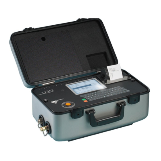
- Page 1 LPA² Analyser User Guide www.mpfiltri.co.uk 200.053-EN...
- Page 2 Covers Model Numbers LPA² SAFETY WARNING Hydraulic systems contain dangerous fluids at high pressures and temperatures. Installation, servicing and adjustment is only to be performed by qualified personnel. Do not tamper with this device. Document Revision 16.1...
- Page 3 Contents Precautions • • • Battery Internal Cleaning LCD Visibility Introduction Online Operation • • • Main / Test Progress Screen Analyser Settings Preparing Analyser • • • For Test Interpreting Results Further Tests Shutting Down Continuous Sampling • Continuous Sampling – Basic Operation Moisture Sensor Alarms Wiring...
- Page 4 13 Warranty • Recalibration Measuring Water in Hydraulic and Lubricating Fluids ISO4406:1999 Cleanliness Code System NAS1638 Cleanliness Code System SAE AS4059 REV.E Cleanliness Classification For Hydraulic Fluids Recommendations Hydraulic System Target Cleanliness Levels New ISO Medium Test Dust and its effect on ISO Contamination Control Standards •...
-
Page 5: Precautions
1 Precautions The default language setting for the LPA² Laser Particle Analyser is English. To change the language setting refer to page 12. 1.1 Battery It is recommended that the LPA² be charged for a minimum of 24 hours prior to first use, to fully charge the internal battery. 1.2 Internal Cleaning Do NOT clean the LPA²... -
Page 6: Introduction
2 Introduction The LPA² is designed to measure and quantify the numbers of solid contaminants in Hydraulic, Lubrication and Transmission applica- tions. The LPA² is designed to be a laboratory accurate instrument suitable for "on-site’’ applications utilising mineral oil as the oper- ating fluid. - Page 7 Introduction...
-
Page 8: Online Operation
3 Online Operation 1. Insert WASTE FLUID HOSE in to the waste disposal bottle pro- vided. Important! Do not connect Waste Fluid Hose to a pressurised system, as this will cause the Analyser to malfunction and could cause internal leakage. The Waste Fluid Hose must be dis- charged into the waste disposal bottle provided, or into a tank/ves- sel vented to atmosphere. - Page 9 3.1 Main / Test Progress Screen Figure 1 Main Test Screen - Starts sampling and emptying cycle START - Stops test at any point in the sampling/ emptying cycle. Next STOP test will start with an emptying cycle before the test commences, - Prints test results.
- Page 10 • Recall – Recalls results from memory • Print – Prints recalled results : Adjusts the screen contrast. 7 Darker 8 Lighter. CONTRAST +/- – see page 35 LOW BATTERY INDICATOR Online Operation...
- Page 11 3.2 Analyser Settings Press the button 5 to program the Analyser to your require- ments. The main "Settings Screen’’ will be displayed. To alter the Analyser settings progress through the following routine from this screen. 1) Test Ref: machine one 2) Test Number: 123 3) Time and Date 4) Result Presentation Options...
- Page 12 3.2.3 Time and Date 3 Press 3 , then use the keypad to set the time and date. Cycle Count A cumulative cycle count is also displayed on the Time & Date screen. This count automatically increases by 1 each time a test is taken.
- Page 13 0. English (Default) 1. Italian 2. French 3. German 4. Chinese For selection of language proceed as follows: − Press 6 . − Enter chosen value (e.g. 1←for Italian). − Press key 0 (zero) − Press key 0 (zero) − Wait 5 seconds −...
-
Page 14: Continuous Sampling
a longer period of time. Unit is flushed in between tests to ensure each sample is representative of its point in time. Triple / Bottle Sampling – A triple test with results average and quicker than the Dynamic Test: 24ml sample volume comprised of three individual 8 ml samples tested consecutively. - Page 15 8 Press flush valve push button to open flush valve – push button illu- minates to indicate valve is open. Leave valve open for at least one minute or 200ml of fluid, to remove any entrapped air and fluid from the previous test ensuring no cross-contamination between samples.
- Page 16 ONLINE – Normal ONLINE – Dynamic Particle count ISO and NAS Code complete and ISO code to with average analysis ISO4406:1999 standard ONLINE – Normal Particle counts displayed – NAS code 1638 standard Online Operation...
- Page 17 The Analyser upper operating limit is set at 24/22/20. Tests that result in particle counts exceeding any scale number in the three part ISO code upper limit has the scale number re- placed by an asterisk. Also, the associated particle counts on the printout are replaced by X’s.
- Page 18 3.5.2 Different Sampling Point/ Same System To carry out this new test repeat steps 8 to 13 on page 14. To change test reference/ test mode data, repeat steps 1 to 13 on page 11. 3.5.3 New System To carry out this test repeat steps 1 to 13 on page 11. 3.6 Shutting Down 1.
- Page 19 4 Continuous Sampling The LPA² can be selected for continuous testing at set time intervals. Once continuous sampling has started the LPA²’s flush valve auto- matically opens and closes before each test. This allows representa- tive fluid to reach the sensing arrangement before the 15ml sampling test commences.
- Page 20 Important! Do not connect Waste Fluid Hose to a pressurised system, as this will cause the LPA² to malfunction and could cause internal leakage. The Waste Fluid Hose must be dis- charged into a tank/ vessel vented to atmosphere. To conserve battery life, the LPA² should be permanently connected to the power adaptor when it is operated in the continuous sampling mode.
- Page 21 5 used to input the Clean Alarm Level when using the NAS1638 / AS4059E-1 format. Enter 0 if not used. 6 used to enter the Clean Alarm Level when using the AS4059E-2 format. Enter 0 if not used. (This Alarm Level will now be displayed as *A/*B/*C/*D/*E/*F).
- Page 22 4.1.1 Continuous Sampling – with Clean Alarm Levels – Alarm Mode 1 This operating mode is similar to the Basic Operation, but in this mode the LPA² will stop testing when the specified clean alarm level is achieved. A status of is shown on the LCD when the specified COMPLETED clean alarm level is achieved.
- Page 23 Selecting instructs the Analyser CONFIRM CLEANLINESS LEVEL: ON to repeat the sampling cycle until the Clean alarm level has been achieved in two consecutive samples, before the Completed sta- tus is displayed. Selecting CONFIRM CLEANLINESS LEVEL: OFF permits the Clean alarm to be achieved only one time before the Completed status is displayed.
- Page 24 Size Code A: 000to 12 Size Code B: 00 to 12 Size Code C: 00 to 12 Size Code D: 2 to 12 Size Code E: 4 to 12 Size Code F: 7 to 12 Example, 4A/4B/5C/6D/6E/7F For continuous testing until the AS4059E Table 2 size codes are achieved, select , as described in AS4059E TABLE 2 FORMAT...
- Page 25 of pressing Start button automatically closes the Flush valve before sampling commences. 13 Press button 1 START The Analyser will now commence the sampling cycles 14 The completion progress bar indicates the status of the test. • Results will be automatically displayed on the screen after each test.
-
Page 26: Moisture Sensor
5 Moisture Sensor The LPA² version fitted with the optional moisture sensor module allows both measurement of % saturation of water in oil (Relative Humidity) and temperature. These are displayed as RH % and °C on the main/test progress screen and on the printed results. Temperature measurement provides a reference temperature for the RH reading. -
Page 27: Alarms
1) Minutes Between Tests: 0 2) Log Every Test: On 3) Confirm Cleanliness Level: Off 4) Clean Alarm Level (ISO): 0 5) Clean Alarm Level (NAS1638/AS4059E-1):0 6) Clean Alarm Level (AS4059E-2): 1A/2B/3C/4D/5E/6F 7) RH Test: On Press a Key to Choose or 0 to Exit Press 7 to change RH Test status to ON or OFF. -
Page 28: Wiring
6 Alarms Access the Operations screen as described on page 11 and press 7 . The Alarm Options screen will be displayed. ALARM OPTIONS 1) Alarm Mode: 1 2) Dirty Alarm Level (ISO): 0 3) Dirty Alarm Level (NAS1638 / AS4059E-1): 4) Dirty Alarm Level (AS4059E-2): 1A/2B/3C/4D/5E/6F Press a Key to Choose or 0 to Exit... - Page 29 Clean alarm levels are set in accordance with the instructions start- ing on . Alarm mode 1 is used in conjunction with the Con- page 22 tinuous Sampling test type, enabling the Analyser to operate contin- uously until the specified clean alarm level is achieved. 3 Alarm Mode: 2 Selecting option 2 arranges the relays to operate when the Clean and Dirty alarm levels are reached/exceeded.
- Page 30 Relay 2 (Clean) NAS/AS4059E-1 single num- result <= set limit result > set limit Off ISO/AS4059E-2 multi-part all results <= corresponding set On limit any result > corresponding set Off limit Alarm Modes: 3 and 4 These are reserved for future development. Alarms...
- Page 31 7 Wiring The LPA² contains two solid state relays which can be used to switch an external circuit, when using the Continuous Test mode. The func- tion of these relays for Alarm Mode 1 is shown in the following sim- ple wiring diagrams, using a battery and bulb circuit for illustrative purposes.
- Page 32 Example 1: Bulb illuminates Example 2: Bulb illuminates when Clean alarm level is during sampling and achieved (completed status), extinguishes when Clean and is off during sampling. alarm level is achieved (completed status is shown on LPA²). (Relay 1 is also closed during Normal, Dynamic, Triple &...
-
Page 33: Bottle Sampling
8 Bottle Sampling An alternative to operating on-line is to use MP Filtri UK’s Bottle Sampling Unit to test oil contained in bottles. Refer to the separate User Guide for details. Bottle Sampling... -
Page 34: Data Logging
9 Data Logging Press the Log button 6 to access results stored within the LPA²’s memory, the Log Screen will be displayed. 1) Transfer Log 2) Clear Log 3) Clear Last 4) Recall 5) Print Press a Key to Choose or 0 to Exit To view the contents of the LPA²’s memory progress through the following routine - •... -
Page 35: Battery Charging
10 Battery Charging The LPA² is equipped with an internal rechargeable battery capa- ble of sustaining 8 hours continuous operation following a 24 hour charging period (approximately 100 tests). To conserve battery power the LCD screen is illuminated at a re- duced level when the LPA²... -
Page 36: Printer Paper
11 Printer Paper To access the thermal printer, remove the four thumbscrews securing the cover and serrated paper cutter. Thermal printer paper is sensi- tised on one side only and must be fed into the printer mechanism as shown below. SERRATED CUTTER THERMAL PRINT HEAD ROLLER... - Page 37 IMPORTANT The thermal printer must not be operated with- out paper, as this will damage the printer. Therefore, replace the roll when the "end of the roll’’ indication appears on the paper. Printer Paper...
-
Page 38: Software Installation
12 Computer Analysis 12.1 Software Installation Install software on to a suitable PC running Windows XP or later. Follow instructions as detailed in the LPA-View User Manual. 12.2 Results Download Connect RS232 cable to LPA² and PC via an appropriate port. Switch ON the LPA². -
Page 39: Warranty
Please fill in online 13.1 Recalibration MP Filtri UK will only verify the accuracy of the LPA² if the unit is recalibrated every 12 months. Please ensure that the test results in the Log are downloaded to LPA-View before the LPA²... - Page 40 Warranty...
-
Page 41: A Measuring Water In Hydraulic And Lubricating Fluids
Appendix A Measuring Water in Hydraulic and Lubricating Fluids From North Notts Fluid Power Centre In mineral oils and non aqueous fire resistant fluids water is undesirable. Min- eral oil usually has a water content of 50-300 ppm which it can support with- out adverse consequences. - Page 42 Appendix A Typical Water Saturation Levels For New Oils Figure I Examples: Hydraulic oil @ 30°C = 200ppm = 100% saturation Hydraulic oil @ 65°C = 500ppm = 100% saturation Measuring Water Content...
-
Page 43: B Iso4406:1999 Cleanliness Code System
Appendix B ISO4406:1999 Cleanliness Code System The International Standards Orga- nization standard ISO 4406:1999 is the preferred method of quoting the number of solid contaminant par- ticles in a sample. The code is constructed from the combination of three scale numbers selected from the following table. - Page 44 Appendix B Microscope counting examines the particles differently to APCs and the code is given with two scale numbers only. These are at 5 µm and 15 µm equivalent to the 6 µm(c) and 14 µm(c) of the APCs. ISO4406:1999 Cleanliness Code System...
-
Page 45: C Nas1638 Cleanliness Code System
Appendix C NAS1638 Cleanliness Code System The NAS system was originally developed in 1964 to define contamination classes for the contamination contained within aircraft components. The ap- plication of this standard was extended to industrial hydraulic systems simply because nothing else existed at the time. The coding system defines the max- imum numbers permitted of 100ml volume at various size intervals (differ- ential counts) rather than using cumulative counts as in ISO 4406:1999. - Page 46 Appendix D SAE AS4059 REV.E Cleanliness VIII Classification For Hydraulic Fluids This SAE Aerospace Standard (AS) defines cleanliness levels for particulate contamination of hydraulic fluids and includes methods of reporting data re- lating to the contamination levels. Tables 1 and 2 below provide the Max- imum Contamination Limits (Particles/100ml) of differential and cumula- tive particle counts respectively for counts obtained by an automatic particle counter, e.g.
- Page 47 Appendix D Size range μm(c): 6 - 14 14 - 21 21 - 38 38 - 70 >70 Class 1,000 2,000 4,000 8,000 1,425 16,000 2,850 32,000 5.700 1,012 64,000 11,400 2,025 128,000 22,800 4,050 256,000 45,600 8,100 1,440 512,000 91,200 16,200 2,880...
- Page 48 Appendix D Size μm(c) >4 >6 >14 >21 >38 >70 Size Code Classes 1,560 3,120 1,217 6,250 2,432 12,500 4,864 25,000 9,731 1,731 50,000 19,462 3,462 100,000 38,924 6,924 1,224 200,000 77,849 13,849 2,449 400,000 155,698 27,698 4,898 800,000 311,396 55,396 9,796 1,696 11 1,600,000...
- Page 49 Appendix E Recommendations Unit Type ISO 4406:1999 Code PUMP Piston (slow speed, in-line) 22/20/16 Piston (high speed, variable) 17/15/13 Gear 19/17/15 Vane 18/16/14 MOTOR Axial piston 18/16/13 Radial piston 19/17/13 Gear 20/18/15 Vane 19/17/14 VALVE Directional (solenoid) 20/18/15 Pressure control (modulating) 19/17/14 Flow control 19/17/14 Check valve...
- Page 50 Appendix E fluids which are cleaner than those stated will increase life. However, the di- versity of hydraulic systems in terms of pressure, duty cycles, environments, lubrication required, contaminant types, etc, makes it almost impossible to predict the components service life over and above that which can be rea- sonably expected.
-
Page 51: F Hydraulic System Target Cleanliness Levels
Appendix F Hydraulic System Target Cleanliness Levels Where a hydraulic system user has been able to check cleanliness levels over a considerable period, the acceptability, or otherwise, of those levels can be verified. Thus if no failures have occurred, the average level measured may well be one which could be made a bench mark. - Page 52 Appendix F Contamination Corresponding Recommended Typical Codes Codes Filtration Applications ISO 4406:1999 NAS 1638 Degree Bx200 μm(c) μm(c) μm(c) High precision and laboratory servo-sys- tems Robotic and servo-systems 10-12 Very sensitive - high reliability systems 12-15 Sensitive - reliable systems 15-25 General equipment of limited reliability...
-
Page 53: G New Iso Medium Test Dust And Its Effect On Iso Contamination Control Standards
Appendix G New ISO Medium Test Dust and its effect on ISO Contamination Control Standards When General Motors gave advance warning to the International Standards Organization (ISO) that it was intending to stop the production of AC Fine Test Dust (ACFTD), work commenced immediately on finding an improved replacement dust. - Page 54 Appendix G ISO therefore defined the requirements for the replacement for ACFTD and asked the National Institute of Standards and Technology (NIST) in the USA to produce a standard, traceable reference material. The new dust’s parti- cle size distribution has been accurately determined with the aid of modern scanning electron microscope and image analysis techniques.
- Page 55 Appendix G The standards affected include: ISO 4402:1991 Hydraulic fluid power Calibration of liquid automatic particle counters. ISO 4406:1987 Hydraulic fluid power Code for defining the level of contamination by solid par- ticles. ISO 4572:1981 Hydraulic fluid power – Filters Multi-pass method for evaluating filtration performance of a filter element.
- Page 56 Appendix G To clarify matters still further, ISO standards written around the new test dust will utilize a new identifier, ‘(c)’. Hence µm sizes according to the new ISO 11171 will be expresses as ‘µm(c)’ and Beta ratios according to ISO 16889 will be expressed as ‘Bx(c)’, e.g.‘B5(c)’.
- Page 57 Appendix G Particle Size Obtained Using Correlation ACFTD ISO/NIST (ISO (ISO 11171) 4402:1991) The table shows the correla- µm µm(c) tion between Particle Sizes Obtained using ACFTD (ISO 4402:1991) and NIST (ISO 11171) Calibration Methods This table is only a guideline. 10.6 11.3 The exact relationship between...
-
Page 58: Other Standards
Appendix G Other Standards Although the ISO 4406:1999 standard is being used extensively within the hydraulics industry other standards are occasionally required and a compar- ison may be requested. The following table gives a very general comparison but often no direct comparison is possible due to the different classes and sizes involved. - Page 59 Appendix G XIII ISO 4406:1999 DEF.STD 05/42 [7] NAS 1638[5] SAE 749[8] Table A Table B ISO 11218[6] 13/11/08 14/12/09 15/13/10 16/14/09 400F 16/14/11 17/15/09 17/15/10 800F 17/15/12 18/16/10 18/16/11 1,300F 18/16/13 19/17/11 1,300 2000F 19/17/14 20/18/12 2,000 20/18/13 4,400F 20/18/15 21/19/13 4,400...
- Page 60 Appendix H Clean working practises The majority of hydraulic systems require cleanliness which controls below around a 40 micron threshold (beyond the limit of human eyesight). When analysing particles down to levels of 4um, 6um & 14um you are talking about objects of a cellular/bacterial size.
- Page 61 Appendix H • Do perform a statistically large enough sample of particle analysis results ( 25) to arrive at a base cleanliness level for your system. • Do make sure that filters are correctly sized for your applications and cleanliness you are trying to achieve. Don’ts •...
- Page 62 Appendix I Specification As a policy of continual improvement, MP Filtri UK reserve the right to alter the specification without prior notice. Technology Automatic Optical Particle Analyser Optical Package Twin Laser and Twin Optical Diode Detectors Display Backlight graphical LCD Sensitivity >4,6,14,21,25,38,50,70 μm(c) sizes to revised ISO...
- Page 63 Appendix I LPA² Sample volume 15 ml. (normal) 30 ml. (dynamic) 24 ml. (bottle sampler) 15 ml. (continuous) 8ml. (short) Operation Max. system working pressure: 400 bar. Min. working pressure: 2 bar Viscosity range to 400 centistokes Operating temperature +5 to +80°C Fluid compatibility Mineral oil &...
-
Page 64: J Spare Product / Part Numbers
Appendix J Spare Product / Part Numbers For spares and part numbers please see the website: www.mpfiltri.co.uk Spare Product / Part Numbers... - Page 65 Appendix K COM Ports The LPA² uses the RS232 connection standard to interface with a computer. If the computer does not have a built-in RS232 ("COM’’) port, a USB:RS232 adaptor can be used. Connection Using a USB Port This is used when a built-in RS232 port is not available. When using a USB Adaptor provided with the LPA²: •...
- Page 66 Appendix K Determining the COM Port To check the COM port number allocated by the computer for the Serial lead or the USB to Serial Connector: • Windows 2000, Windows XP, Windows Vista − Right click on My Computer icon and then left click on Properties. −...
- Page 67 Confirm that there is a free flow of fluid to the Analyser, by depressing the Flush Valve and ob- serving fluid passing into the waste disposal bot- High water/aeration levels. (If suspected contact MP Filtri UK for further advice) Fault Finding...
- Page 68 Appendix L If excessive system contamination is suspected, flush out the Analyser using a Bottle Sampling Unit in conjunction with a suitable solvent. The standard LPA² and the standard Bottle Sampling units are both fitted with Nitrile seals, so Petroleum Ether may be used for this purpose. Petroleum Ether is not compatible with seals manufactured from EPDM, which are used in the Phosphate Ester version of the 250 Bottle Sam- pling unit.
- Page 69 Appendix L Language Settings LPA² Language settings To change the language setting to English: • Press the green button to switch the LPA² ON • Wait for the characters to appear on the LCD screen • Press key 5 • Press key 4 •...
- Page 70 Appendix L Fault Finding...
- Page 71 Produced by MP Filtri UK Revision 16.1 As a policy of continual improvement, MP Filtri UK reserve the right to alter specifi- cations without prior notice. Except as permitted by such licence, no part of this publication may be reproduced, stored in retrieval system or transmitted, in any form or any means, electronic, me- chanical, recording, or otherwise, without prior written permission of MP Filtri UK.
- Page 72 Fax: +1.905-303-7256 Email: s.mishra@mpfiltri.com Email: mail@mpfiltricanada.com Website: www.mpfiltri.com Website: www.mpfiltricanada.com RUSSIAN FEDERATION CHINA MP FILTRI RUSSIA INC MP FILTRI (Shanghai) Co Ltd Phone mobile: +7.095-502-5411 Tel: +86.21-58919916 Fax: +7.095-205-9410 Fax: + 86.21-58919667 Email: mpfiltrirussia@yahoo.com Email: sales@mpfiltrishanghai.com Website: www.mpfiltri.ru Website: www.mpfiltrichina.com GERMANY MP FILTRI USA Inc.
Need help?
Do you have a question about the LPA2 and is the answer not in the manual?
Questions and answers