Table of Contents
Advertisement
Advertisement
Table of Contents

Summary of Contents for MP Filtri ICM
-
Page 1: User Guide
Inline Contamination Monitor 2.0 User Guide www.mpfiltri.co.uk 201.008-EN... -
Page 2: Fixed - Nas1638 And Rh • Time Multiplexed Schemes • Time Multiplexed - Scheme
Covers All ICM Models except -AZ2 (ATEX) Safety Warning Hydraulic systems contain dangerous fluids at high pressures and tempera- tures. Installation, servicing and adjustment is only to be performed by qual- ified personnel. Do not tamper with this device. Document Revision 2.0... -
Page 3: Table Of Contents
Contents Introduction • Operating Principle How to Order • Related Products Specification • • • • • • Performance Hydraulic Environmental Physical Electrical Warranty and Recalibration Status LED Front Panel Operation • • Result Display Diagnostics Display Water Sensor Data Logger •... - Page 4 13 Installation • Installation Procedure 14 Electrical Interface • • • • Electrical Connectors DC Power Machine Connector - Serial Interface Switched Input and • • • Output Signals Start Signal Alarm Outputs 4-20mA Connection 15 Hydraulic Connection • • •...
- Page 5 New ISO Medium Test Dust and its effect on ISO Contamination Control Standards • • • • • Calibration New Test Dust Benefits Effect on Industry Correlation Other Standards Clean working practises...
-
Page 7: Introduction
The graphical LCD allows direct local display of the results in any selected format. ICM-W models also perform a measurement of % saturation of Water in oil (RH), and fluid temperature (°C). -
Page 8: How To Order
2 How to Order Example: Example: Common Features – All versions can be controlled by a PC, PLC or the ICM-RDU Remote Display Unit. Included is time- stamped data-logging for around 4000 tests, an integral status LED to indicate fault conditions, RS485/CANBUS/4-20mA communications and measurement in multiple international standard formats. -
Page 9: Related Products
ICM. Figure 2.2 USBi It is a USB:RS485 interface with a terminal block pre-wired with the ICM cable. An extra terminal block is provided for any customer wiring to external devices. An external DC adapter can be used to power the complete system, or if the computer is always connected during use, power can be taken directly from the USB cable. -
Page 10: Specification
AS4059 Rev.E. Table 2 Sizes A-F : 000 to 12 Lower Limits are Test Time dependent. If system above 22/21/18 or approx. NAS 12 a coarse screen filter should be fitted to prevent blockage. This is available from MP Filtri UK Part SK0040. Reporting Formats ISO 4406:1999 (ICM Default) - Page 11 420 bar static. For high frequency pressure pulse applications contact MP Filtri UK. Differential (Inlet-Outlet) Typically 0.5 bar, see section 15.1. Pressure Seal Material [M,N] Viton. Contact MP Filtri UK for any fluids that are incompatible with Viton seals. Seal Material [S] Perflouro-elastomer. 3.3 Environmental Ambient Temperature -25 to + 80 °C for non Kversion, -25 to + 55°C for Kversion...
-
Page 12: Recalibration
>3m and / or devices connected to DC supply networks subject to lightning surge. We therefore only certify the ICM for installations with a cable <3m and that are powered from a dedi- cated surge-protected DC supply or DC outlet. -
Page 13: Status Led
All ICM versions have a multicolour indicator on the front panel, which is used to indicate the status or alarm state. ICM-K versions also have a screen that changes colour. The alarm thresholds can be set from LPA-View via the serial interface. - Page 14 The LED can also indicate various fault codes by turning red and flashing white a number of times, see section 16.1. Status LED...
-
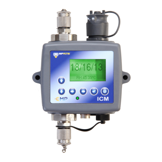
Page 15: Front Panel Operation
5 Front Panel Operation 5.1 Result Display ICM-K models have a 6 button keypad and a small graphical LCD. This allows the display of the test result (current cleanli- ness level, with water content and temperature if applicable). Figure 5.1 The graphical format allows a full display of all codes of the standards supported. - Page 16 FLOW will also appear here. The second screen shows diagnostics relating to Modbus serial communications traffic. External Comms Errors are those between a connected PC and the ICM. Internal Comms Errors are internal to the unit, showing communications between the ICM keyboard/display circuit board and the sensor itself.
- Page 17 Simple Detailed Figure 5.4 AS4059E Table 2 Simple Detailed Figure 5.5 AS4059E Table 1 Simple Detailed Figure 5.6 ISO11218 (Draft) Front Panel Operation...
- Page 18 Figure 5.7 History Screen General Modbus CAN Bus Figure 5.8 Diagnostic Screens Front Panel Operation...
-
Page 19: Water Sensor
6 Water Sensor ICM-W models measure water content using a capacitive RH (relative humidity) sensor. The result is expressed as percentage saturation. 100% RH corresponds to the point at which free water exists in the fluid, i.e. the fluid is no longer able to hold the water in a dissolved solution. -
Page 20: Data Logger
/ indicator will turn red. If this happens the operator can remove the stick and try again with a new one. Factory setting for ICM system time is GMT, it can be updated to local time via Usbi and/or Modbus. Data Logger... - Page 21 The USB stick provided with the unit is pre-formatted for the transfer. Other USB sticks may need to be re-formatted (FAT32) Data Logger...
-
Page 22: Remote Display Unit Option
The sensor itself is mounted remotely in another box. This allows the operator full control of the ICM even when the sensor itself is not easily accessible. The ICM- RDU connects "in between’’ the incoming supply/serial connections, and the ICM sensor. -
Page 23: Optional Computer Usb Interface
9 Optional Computer USB Interface Figure 9.1 ICM-USBi: A USB Interface Unit for the ICM The USBi is a ready-made solution for easily connecting a computer to the ICM. It includes a USB:RS485 interface with a terminal block pre-wired with the ICM cable. -
Page 24: Remote Control
10 Remote Control The ICM can be controlled using the remote control facility included in the LPA- View software package, installed on a PC. Alternatively customers can use their own software running on a PC or PLC. Since the ICM includes a built-in datalogging memory, operators can make use of •... - Page 25 Select the one used to connect the ICM, then press OK. If you are unsure which port is correct, the device name should be next to the COM port number. When communication has been established successfully, the remote control dialogue will appear.
-
Page 26: Pc Software Operation
11 PC Software Operation The Remote Control dialogue allows an operator to manually control the ICM from a PC, using the LPA-View software. It can also be used to download test results that have accumulated during autonomous (disconnected) operation. Figure 11.1 The Remote Control dialogue To perform a test, first optionally edit the Test Reference and press Apply to set the new value. - Page 27 If the status is Ready then the operator can press the Start button again to begin a new test. It is also possible to configure the ICM to automatically begin another test, after an optional delay. In this case the status will be Testing or Waiting.
-
Page 28: Settings
Figure 12.1 Remote Device Settings dialogue The ICM has been designed to be a very flexible product, so has a wide range of settings and operat- ing modes. However the shipped defaults are suitable for most applications and many users can skip this section. - Page 29 Current Time shows the time set on the ICM. It is important that this is correct since this is used to timestamp the tests. Pressing the Set button automatically synchronises the ICM time to that on the computer.
- Page 30 This setting can be used when there is no flow available but communications need to be tested. • The ICM uses the width of the pulse to derive flow, its flow output is only an 12.6 Low Flow Alarm Disabled (Clean Systems) •...
- Page 31 If continuous logging is used, then the Log Interval can be set to control the pro- portion of tests that are actually logged. For example the ICM could be set to test every 10 minutes, but only log a result hourly. The log interval, test interval and test duration are distinct parameters that work together to control the test and data logging.
- Page 32 12.8.1 Alarm LED The front panel LED also indicates these alarm states to the operator (see section 12.8.2 Alarm Levels The various alarm thresholds are set in the Contamination Code Target / Alarm Levels area of the dialogue. Figure 12.2 ISO4406:1999 Alarm Levels Alarms can be set on combinations of cleanliness codes, water content and tem- perature.
- Page 33 the ISO4406:1999 test Format and then entering values as required. As an exten- sion to ISO4406:1999 it is also possible to specify codes for the other measured sizes too. If this is not needed then the entries can be left blank. NAS1638 Alarm Levels NAS1638 can be used by selecting this as the test Format.
- Page 34 The Alarm Mode sets the precise function of the two switched alarm outputs of the ICM. 12 13 This allows the ICM to be used in a variety of situations. Note that the conditions under which the outputs are turned on are also displayed above the Alarm Mode selector, for each setting.
- Page 35 Intended Function Warning Alarm This allows the ICM to switch external warning lights or alarms. Output 1 is the "Warning’’ output, switching on if any of the Lower limits are exceeded. Output 2 is the "Alarm’’ output, behaving similarly for the upper limit.
- Page 36 is greater than the lower limit. If the result is in between, both outputs are turned on and the LED colour will be amber (i.e. a mixture of red and green light). Alarm Mode 3: Particles-Water Output 1 Output 2 Turns on When Cleanliness>Upper Water>Upper Turns off when...
- Page 37 Turns on When Test Complete >Lower Intended Function Test Complete Signal "not clean’’ Signal This is used when controlling tests from a PLC using switched outputs. The PLC gives a start signal, then monitors the "Test Complete’’ output. If the test has failed it can detect this with the "not clean’’...
-
Page 38: Installation
One solution is the ICM-FC1 pressure compensated flow control valve. This limits the flow to around 200ml/minute for differential pressures up • Fix mechanically. to 400 bar. This should be fitted to the drain side of the ICM (the top fitting). Installation... - Page 39 This is because any length of pipe between the ICM and a downstream restrictor can act as an accumu- lator. Any pressure pulsations (for example from a pump) in the feed to the ICM are then translated into pulsations in flow rate, sometimes leading to flow reversals in time with the pulsations.
-
Page 40: Electrical Interface
14 Electrical Interface Note: The separate ICM-USBi product is available for those wishing to simply plug the ICM into a computer. This section is for those wishing to do their own wiring to the product. 14.1 Electrical Connectors The ICM has two circular connectors located on the lower face of the unit. The USBi product can be connected to either one depending on the installation config- uration. - Page 41 a start signal input, two relay outputs, and a data pair that can be set to RS485, CANbus or 4-20mA signalling modes. This is the circular connector closest to the hydraulic connection. Figure 14.1 Machine Connector External Wiring Example In Figure 14.1 an example installation is shown.
- Page 42 LPA-View software. To provide a reference the RS485 0V connection should also be linked to the ICM 0V (as shown on the drawing). The standard ICM control protocol is Modbus RTU. Modbus is a freely available open standard for industrial control.
- Page 43 ICM-RDU Remote Display Unit. The RDU is used when the ICM location is not convenient for an operator. It can control and monitor a remote ICM, as well as allowing an external controller to be connected to it (for data download, for example).
- Page 44 RS485 interface is more flexible but requires more software work if LPA-View is not used (e.g. control from a PLC). An alternative is to control the ICM via these switched I/Os, either from a PLC or using a manual switch and indicators.
-
Page 45: Alarm Outputs
Voltage 9V DC 36V DC Impedance 10k Ohms • From the ICM front panel Other ways to start a test are: • Via LPA-View or PLC Modbus command. button, if fitted (K Keyboard option). START • Periodic automatic testing according to a programmed test mode. - Page 46 For details of how the test results are represented by the 4-20mA signals, see chap- ter 20. Electrical Interface...
- Page 47 Figure 14.6 Electrical Interface...
-
Page 48: Hydraulic Connection
ICM. 15.1 Flow Rate 15.1.1 Summary For the majority of systems, a differential pressure of a few Bar will generate an in-range flow for an ICM connected using two 1.5 meter lengths of Mini-mess Hydraulic Connection... - Page 49 15.1.2 Detailed Calculations In general the flow rate of fluid through the ICM needs to be kept within the range of the unit (see hydraulic specification 3.2). The ICM measures the flow during operation, so this can be used to check that the flow is correct.
- Page 50 20 - 400 ml/min. It can be seen that the unit will accommodate a 20:1 variation in either viscosity or differential pressure during operation. In fact the ICM will work perfectly well at a lower flow, for example 100ml/minute, in which case a 2 Bar check-valve could be used.
- Page 51 • The flow controller must be fitted to the outlet only. If fitted to the inlet it will control the flow from a pressure larger than this has a risk of blockage. • The flow controller must be fitted directly to the ICM outlet port. have a filtering effect.
- Page 52 A pressure compensated flow control valve is fitted to the ICM drain outlet. A suit- able valve is the ICM-FC1 (see 2.1.2), but other ones can be used too. This has the effect of a ``flow limiter’’, maintaining a constant flow rate even with a vary- ing inlet pressure (provided this pressure stays above a minimum working value).
-
Page 53: Fault Finding
16 Fault Finding 16.1 LED Flashing / Fault Codes The ICM front panel led indicates a fault by a number of white flashes, with a red background. The number of flashes indicates the fault code: 1. Optical - An optical fault could indicate LED failure or blockage of the optical path. - Page 54 The standard ICM is fitted with Viton seals, so Petroleum Ether or Iso Propyl Al- cohol may be used for this purpose, in conjunction with the MP Filtri UK Bottle Sampling Unit.
- Page 55 DO NOT USE ACETONE Fault Finding...
-
Page 56: Cycle Time And Flow Rate Considerations
17 Cycle Time and Flow Rate Considerations The set Test Duration is the amount of time for which particle counts are accumu- lated, before the test result is updated. The default of 120 seconds is likely to be suitable for most applications. However it is possible to set other values. A shorter time enables the unit to respond more quickly to variations in cleanliness. - Page 57 1000 400ml/minute (max. flow) 200ml/minute (ideal flow) 20ml/minute (min. flow) ISO Code Figure 17.1 Test Time needed for Reliable Indication by ISO code Cycle Time and Flow Rate Considerations...
-
Page 58: Modbus
Modbus RTU protocol. It is possible to control every aspect and setting of the ICM, as is done by the MP Filtri UK LPA-View control software. All results and counts are available in all supported formats. One scenario is to use LPA-View to initially configure the ICM, then the customer-written software only has to read the test results. -
Page 59: Canbus
19 CANbus The ICM can also communicate using CANbus. Communication is via raw CANbus frames but the message IDs have been chosen to be compatible with both the J1939 and CAN-Open standards. For more details refer to the separate ICM-CANBUS manual. -
Page 60: Analog 4-20Ma Modes
20 Analog 4-20mA Modes The ICM provides two analog 4-20mA current loop outputs, A and B. In order to provide the possibility of transmitting more than two parameters, several different modes can be chosen to suit the application. 20.1 Fixed - NAS1638 and RH The ICM result format must be set to NAS1638. - Page 61 • We use an "out of range" current of >20mA (24mA) to indicate parameter not • The sequence is then repeated. available 20.2.1 RH Coding ���� = 6 + (���� % /10) The RH value is encoded according to the formula (20.1) ����% = (����...
- Page 62 20.2.4 ISO4406 Parameters are output in the sequence <SYNC> <ISO4> <ISO6> <ISO14> <ISO21> <ISO25> <ISO38> <ISO50> <ISO70> <RH> <TEMP> <...> ���� = 6 + ������/2 ISO4406 codes are encoded as (20.6) ������ = 2 × (���� − 6) (20.7) So 6mA = ISO 0, 20mA = ISO28 20.2.5 AS4059E2 Parameters are output in the sequence: <SYNC>...
-
Page 63: Measuring Water In Hydraulic And Lubricating Fluids
Appendix A Measuring Water in Hydraulic and Lubricating Fluids From North Notts Fluid Power Centre In mineral oils and non aqueous fire resistant fluids water is undesirable. Mineral oil usually has a water content of 50-300 ppm which it can support without adverse consequences. - Page 64 Appendix A Typical Water Saturation Levels For New Oils Figure 1 Examples: Hydraulic oil @ 30°C = 200ppm = 100% saturation Hydraulic oil @ 65°C = 500ppm = 100% saturation Measuring Water Content...
-
Page 65: Iso4406:1999 Cleanliness Code System
Appendix B ISO4406:1999 Cleanliness Code System The International Standards Orga- nization standard ISO 4406:1999 is the preferred method of quoting the number of solid contaminant particles in a sample. The code is constructed from the combination of three scale num- bers selected from the following ta- ble. - Page 66 Appendix B Microscope counting examines the particles differently to APCs and the code is given with two scale numbers only. These are at 5 µm and 15 µm equivalent to the 6 µm(c) and 14 µm(c) of the APCs. ISO4406:1999 Cleanliness Code System...
-
Page 67: Nas1638 Cleanliness Code System
ISO 4406:1999. Although there is no guidance given in the standard on how to quote the levels, most industrial users quote a single code which is the highest recorded in all sizes and this convention is used on the ICM software. -
Page 68: Dsae As4059 Rev.e Cleanliness Classification For Hydraulic Fluids
Tables 1 and 2 below provide the Maximum Contamination Limits (Particles/100ml) of differential and cumulative particle counts respectively for counts obtained by an automatic particle counter, e.g. ICM. Size range μm(c): 6 - 14 14 - 21 21 - 38 38 - 70 >70... - Page 69 Appendix D Size μm(c) >4 >6 >14 >21 >38 >70 Size Code Classes 1,560 3,120 1,217 6,250 2,432 12,500 4,864 25,000 9,731 1,731 50,000 19,462 3,462 100,000 38,924 6,924 1,224 200,000 77,849 13,849 2,449 400,000 155,698 27,698 4,898 800,000 311,396 55,396 9,796 1,696 11 1,600,000...
-
Page 70: E Recommendations
Appendix E Recommendations Unit Type ISO 4406:1999 Code PUMP Piston (slow speed, in-line) 22/20/16 Piston (high speed, variable) 17/15/13 Gear 19/17/15 Vane 18/16/14 MOTOR Axial piston 18/16/13 Radial piston 19/17/13 Gear 20/18/15 Vane 19/17/14 VALVE Directional (solenoid) 20/18/15 Pressure control (modulating) 19/17/14 Flow control 19/17/14 Check valve... - Page 71 Appendix E the benefits of significant research material and the existence of standard contami- nant sensitivity tests, manufacturers who publish recommendations that are cleaner than competitors may be viewed as having a more sensitive product. Hence there may be a possible source of conflicting information when comparing cleanliness levels recommended from different sources.
-
Page 72: Hydraulic System Target Cleanliness Levels
Appendix F Hydraulic System Target Cleanliness Levels Where a hydraulic system user has been able to check cleanliness levels over a considerable period, the acceptability, or otherwise, of those levels can be verified. Thus if no failures have occurred, the average level measured may well be one which could be made a bench mark. - Page 73 Appendix F Contamination Corresponding Recommended Typical Codes Codes Filtration Applications ISO 4406:1999 NAS 1638 Degree Bx200 μm(c) μm(c) μm(c) High precision and labo- ratory servo-systems Robotic and servo- systems 10-12 Very sensitive - high reliability systems 12-15 Sensitive - reliable sys- tems 15-25 General equipment of...
- Page 74 Appendix G New ISO Medium Test Dust and its effect on ISO Contamination Control Standards When General Motors gave advance warning to the International Standards Organiza- tion (ISO) that it was intending to stop the production of AC Fine Test Dust (ACFTD), work commenced immediately on finding an improved replacement dust.
- Page 75 Appendix G New Test Dust Benefits The new ISO Medium Test Dust (ISO MTD) consists of similar materials to the old ACFTD, but to minimize particle counting errors, it is of a slightly coarser grade be- cause ACFTD included too many particles smaller than 5µm which gave problems during testing.
- Page 76 The following charts shows the correlation between the old ACFTD and the new ISO MTD. The ICM is calibrated with ISO Medium Test Dust (to ISO 11171). The correlation between particle sizes and the ACFTD (old standard) to the ISO MTD (new standard) is as follows : ACFTD <1 5 15 25 30 50...
- Page 77 Appendix G Particle Size Obtained Using Correlation ACFTD ISO/NIST (ISO (ISO 11171) 4402:1991) µm µm(c) The table shows the correla- tion between Particle Sizes Ob- tained using ACFTD (ISO 4402:1991) and NIST (ISO 11171) Cali- bration Methods 10.6 This table is only a guideline. 11.3 The exact relationship between 12.1...
- Page 78 Appendix G possible due to the different classes and sizes involved. ISO 4406:1999 DEF.STD 05/42 [7] NAS 1638[5] SAE 749[8] Table A Table B ISO 11218[6] 13/11/08 14/12/09 15/13/10 16/14/09 400F 16/14/11 17/15/09 17/15/10 800F 17/15/12 18/16/10 18/16/11 1,300F 18/16/13 19/17/11 1,300 2000F...
- Page 79 Appendix H Clean working practises The majority of hydraulic systems require cleanliness which controls below around a 40 micron threshold (beyond the limit of human eyesight). When analysing particles down to levels of 4um, 6um & 14um you are talking about objects of a cellular/bacterial size.
- Page 80 • Don’t eat, drink or smoke around critical systems/processes. Appendix H • Don’t leave tools, objects, clothing or other materials etc. on surfaces or tanks of • Don’t use open tanks on critical systems. critical systems. • Don’t take samples or perform on-line analysis from the top of a reservoir/tank. •...
- Page 81 Produced by MP Filtri UK Revision 2.0 As a policy of continual improvement, MP Filtri UK reserve the right to alter specifications without prior notice. Except as permitted by such licence, no part of this publication may be reproduced, stored in retrieval system or transmitted, in any form or any means, electronic, mechanical, recording, or otherwise, without prior written permission of MP Filtri UK.
Need help?
Do you have a question about the ICM and is the answer not in the manual?
Questions and answers