Table of Contents
Advertisement
Quick Links
Advertisement
Table of Contents

Related Manuals for Watts AERCO CFR 1500


Summary of Contents for Watts AERCO CFR 1500
- Page 1 • 2/9/2024 OMM-0164_B...
-
Page 2: Table Of Contents
CONTENTS Table of Contents SECTION 1. SAFETY PRECAUTIONS ................5 1.1 WARNINGS & CAUTIONS ........................5 1.2 EMERGENCY SHUTDOWN ........................6 1.3 PROLONGED SHUTDOWN ........................6 1.4 IMPORTANT – FOR MASSACHUSETTS INSTALLATIONS ..............6 SECTION 2. EDGE CONTROLLER OPERATION ..............7 2.1 INTRODUCTION ............................. - Page 3 CONTENTS 6.1 OUTDOOR AIR RESET MODE ......................30 6.1.1 Outdoor Air Temperature Sensor Installation ....................30 6.1.2 Outdoor Reset Mode Setup ..........................30 6.2 CONSTANT SETPOINT MODE ......................31 6.3 REMOTE SETPOINT MODE ........................ 32 6.4 DIRECT DRIVE MODES........................32 6.5 COMBINATION CONTROL SYSTEM (CCS) ..................
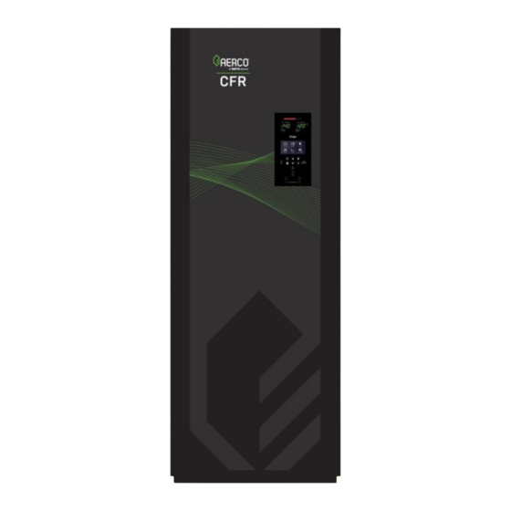
- Page 4 FORWARD FOREWORD The AERCO CFR Boiler utilizes a breakthrough Condensing-Proof technology that maintains dry flue gas while exceeding efficiency standards. It delivers high performance of up to 85.6% thermal efficiency – helping engineers, contractors and owners comply with the latest energy conservation mandates. The CFR Boiler achieves this efficiency while safely reusing existing Category I/Type B venting, allowing for cost-friendly solution in retrofit projects.
-
Page 5: Safety Precautions
SECTION 1 SAFETY PRECAUTIONS SECTION 1. SAFETY PRECAUTIONS 1.1 Warnings & Cautions Installers and operating personnel MUST, at all times, observe all safety regulations. The following warnings and cautions are general and must be given the same attention as specific precautions included in these instructions. -
Page 6: Emergency Shutdown
SECTION 1 SAFETY PRECAUTIONS 1.2 Emergency Shutdown If overheating occurs or gas fails to shut off, close manual shutoff valve (Figure 1-1) external to the unit. NOTE: Installer must identify the location of the emergency shutdown manual gas valve to operating personnel. VALVE CLOSED VALVE... -
Page 7: Edge Controller Operation
SECTION 2 EDGE CONTROLLER OPERATION SECTION 2. EDGE CONTROLLER OPERATION 2.1 Introduction This section provides a brief outline of how to gain access to CFR Boiler’s Edge Controller functionality. The Edge Controller front panel is shown below. This panel’s touchscreen display contains the controls, indicators and displays necessary to operate, adjust and troubleshoot the boiler. -
Page 8: Login And Password Entry
SECTION 2 EDGE CONTROLLER OPERATION 2.2 Login and Password Entry The Edge Controller has multiple levels of password protection. Level Password Description No password The default. Many parameters are visible but “Read Only.” Allows routine maintenance by AERCO Trained Technicians (ATT). A higher-level password for AERCO Master Technicians (AMTs) is distributed on an individual basis. -
Page 9: Start Sequence
SECTION 3 START SEQUENCE SECTION 3. START SEQUENCE 3.1 Introduction The information in this section provides a guide to starting the CFR Boiler using the Edge Controller. It is imperative that the initial startup of this unit be performed by factory trained personnel. Operation prior to initial startup by factory trained personnel may void the equipment warranty. - Page 10 SECTION 3 START SEQUENCE High Pressure Gas Switch Low Pressure Gas Switch Figure 3-1: SSOV Location (P/N 22490 shown) 3. Auxiliary Delay occurs for a configurable length of time and the Delayed Interlocks close. 4. Once all required safety device switches are closed, a purge cycle initiates and: a.
- Page 11 SECTION 3 START SEQUENCE Figure 3-3: Blower Proof Switch and Blocked Inlet Switch Figure 3-4: Ignition Sequence Screen – Purging 6. Upon completion of the purge cycle, the Controller initiates an ignition cycle, and the following events occur: he Air/Fuel Valve rotates to the low-fire (Ignition) position and closes the ignition switch. The Dial on the Air/Fuel Valve will read between 25 and 35 to indicate that the valve is in the low fire position.
-
Page 12: Start/Stop Levels
SECTION 3 START SEQUENCE d) If no spark is present 3 seconds into the ignition trial, the Controller aborts the Ignition Cycle and shuts down the boiler. Refer to SectionSECTION 9 in this guide for guidance if this occurs. Figure 3-4: Air/Fuel Valve in Ignition Position 7. -
Page 13: Start/Stop Levels - Air/Fuel & Energy Input
SECTION 3 START SEQUENCE 3.4 Start/Stop Levels – Air/Fuel & Energy Input The table below shows the relationship between the energy input and A/F Valve position. TABLE 3-2: Air/Fuel Valve Position – NATURAL GAS ENERGY INPUT BOILER ENERGY INPUT A/F VALVE (BTU/HR) (% OF FULL CAPACITY) POSITION... -
Page 14: Initial Start-Up
SECTION 4 INITIAL START-UP SECTION 4. INITIAL START-UP 4.1 Initial Start-Up Requirements The following are the prerequisites for the initial start-up of the CFR boiler: • Complete the installation, per the CFR Boiler Install-Startup Manual (OMM-0163) including gas supply piping, vent installation and condensate drain piping. Starting a unit without the proper piping, venting, or electrical systems can be dangerous and may void the product warranty. -
Page 15: Installing A Gas Supply Manometer
SECTION 4 INITIAL START-UP 4.2.2 Installing a Gas Supply Manometer A 16” W.C. (4.0 kPa) gas supply manometer (or gauge) is used in the following ways: • Mounted on the upstream side of the SSOV to verify that the gas supply pressure is within the required range of 4”... -
Page 16: Accessing The Analyzer Probe Port
SECTION 4 INITIAL START-UP 4.2.3 Accessing the Analyzer Probe Port CFR units contain a 1/4” NPT port on the side of the exhaust manifold, as shown in Figure 4-2. Prepare the port for the combustion analyzer probe as follows: 1. Refer to Figure 4-1 and remove the 1/4” NPT plug from the exhaust manifold. 2. - Page 17 SECTION 4 INITIAL START-UP Figure 4-3: First Manual Combustion Calibration Screen 7. Connect the gas pressure manometer to the upstream side of the gas train’s SSOV (see Section 4.2.2) and connect the Combustion Analyzer and Multimeter (per Section 4.2.3) and ensure that the heating loop is capable of dissipating sufficient heat at full fire.
- Page 18 SECTION 4 INITIAL START-UP 12. Set the Controller’s Enable/Disable switch to Enable. 13. Change the valve position to 30%, press Go, then verify the unit has ignited. 14. Use the (Right) arrow key to change the valve position to 100%, then press Go. 15.
-
Page 19: Reassembly
SECTION 4 INITIAL START-UP 23. Repeat steps 17, 18 and 21 at that valve position and the rest of the valve positions in Table below corresponding to your model. The O , NOx and CO should stay within the ranges shown. TABLE 4-3: NATURAL GAS Final Valve Positions (CFR 3000) Valve Position O2 %... -
Page 20: Adjusting The Automatic Reset Limit Switch Temperature
SECTION 4 INITIAL START-UP Note the following points: • Both switches display the temperature to which the switch is set (the temperature limit), not the actual temperature it is reading. • Both switches can display temperatures in Fahrenheit or Celsius. •... -
Page 21: Changing The Readout Between Fahrenheit And Celsius
SECTION 4 INITIAL START-UP Figure 4-8: Manual Reset Over-Temperature Limit Switch 4.5.3 Changing the Readout Between Fahrenheit and Celsius Perform the following steps to change the temperature reading between Fahrenheit or Celsius. 1. Press and hold both the Increase and Decrease arrows at the same time for about 4 seconds. The display shows the temperature in Celsius and °F changes to °C. -
Page 22: Safety Device Testing
SECTION 5 SAFETY DEVICE TESTING SECTION 5. SAFETY DEVICE TESTING 5.1 Testing of Safety Devices Periodic safety device testing is required to ensure that the control system and safety devices are operating properly. The boiler control system comprehensively monitors all combustion-related safety devices before, during and after the start sequence. -
Page 23: High Gas Pressure Test
SECTION 5 SAFETY DEVICE TESTING 5.3 High Gas Pressure Test To simulate a high gas pressure fault, refer to Figure 4-1 and perform the following steps: 1. Shut off the external gas supply by closing the external gas supply ball valve. 2. -
Page 24: Water Temperature Fault Test
SECTION 5 SAFETY DEVICE TESTING 9. Close the drain and pressure relief valve used in draining the unit. 10. Open the water shut-off valve in the return piping to the unit. 11. Open the water supply shut-off valve to the unit to refill. 12. -
Page 25: Interlock Tests
SECTION 5 SAFETY DEVICE TESTING 1. Once the Automatic Reset Over-Temperature switch setting is approximately just below the actual outlet water temperature, the unit should shut down, the FAULT indicator should flash, and a High- Water Temp Switch Open fault message be displayed. It should not be possible to restart the unit. 2. -
Page 26: Flame Fault Test
SECTION 5 SAFETY DEVICE TESTING 5.7 Flame Fault Test Flame faults can occur during ignition or while the unit is already running. To simulate each of these fault conditions, proceed as follows: 1. Set the Controller’s Enable/Disable switch to Disable. Main Menu →... -
Page 27: Blocked Inlet Switch Test
SECTION 5 SAFETY DEVICE TESTING 4. Set the Enable/Disable switch to Enable and wait for boiler to go into the Purge sequence. 5. After about 5 seconds, with air flowing into the combustion chamber, slowly turn the dial clockwise (to higher value) until the unit trips off with an Air Flow Fault During Purge message. Optionally, attach a manometer and measure the setting at the trip point. -
Page 28: Ssov Proof Of Closure Switch Check
SECTION 5 SAFETY DEVICE TESTING Main Menu → Diagnostics → Manual Mode 4. Go to: and put the unit in Manual Mode, then: a) Ramp boiler to 100% fire rate and set the Controller’s Enable/Disable switch to Enable. b) When the Controller enters ignition phase, it shows Ignition Trial. Attach the alligator clip (Figure 5-8) to any metal surface or ground. -
Page 29: Purge Switch Open During Purge
SECTION 5 SAFETY DEVICE TESTING 5.10 Purge Switch Open During Purge The Purge switch (and Ignition switch) is located on the Air/Fuel Valve. To check the switch: 1. Set the Controller’s Enable/Disable switch to Disable. Main Menu → Diagnostics → Manual Mode 2. -
Page 30: Standalone Modes Of Operation
SECTION 6 STANDALONE MODES OF OPERATION SECTION 6. STANDALONE MODES OF OPERATION The descriptions and instructions in this chapter apply to Standalone units only; the unit cannot be a BST Client or BST Manager. Main Menu → Advanced Setup → BST To verify that the unit is not a BST Client or Manager, go Cascade →... -
Page 31: Constant Setpoint Mode
SECTION 6 STANDALONE MODES OF OPERATION Unit Application = SH Unit Application = Outdoor Reset Figure 6-1: Application Configuration Screen 4. Set the following parameters to define the total outside air temperature span which will be used for Setpoint control. •... -
Page 32: Remote Setpoint Mode
SECTION 6 STANDALONE MODES OF OPERATION 6.3 Remote Setpoint Mode The setpoint can be remotely controlled by an Energy Management System (EMS) or Building Automation System (BAS). The Remote Setpoint can be driven by a current or voltage signal. NOTE: For field wiring instructions see Section 2.10 in the CFR Boiler Install-Startup Manual (OMM-0163). When using the Remote Setpoint mode default setting, 4 - 20 mA/1 - 5 VDC, a 4 to 20 mA/1 to 5 VDC signal, sent by an EMS or BAS, is used to change the unit's setpoint. -
Page 33: Combination Control System (Ccs)
SECTION 6 STANDALONE MODES OF OPERATION To enable the Direct Drive mode: Main Menu → Advanced Setup → Unit →Application Go to: Configuration. 2. Press SH Operating Mode parameter and choose Direct Drive. 3. The Remote Signal parameter now appears. It can be set to one of six options: 4-20mA, 1-5V, BAS, 0-20mA, Network, or 0-5V. -
Page 34: Combination Control System Field Wiring
SECTION 6 STANDALONE MODES OF OPERATION When the combo units are satisfying the domestic load, they are in the Constant Setpoint mode of operation. When the combo units switch over to space heating, their mode of operation changes to follow the ACS command. For more information concerning the operation of the ACS, consult the AERCO Control System Manual (OMM-0081, GF-131);... -
Page 35: Boiler Sequencing Technology
SECTION 7 BOILER SEQUENCING TECHNOLOGY SECTION 7. BOILER SEQUENCING TECHNOLOGY 7.1 Introduction The Boiler Sequencing Technology system (BST) is an integrated 16 boiler control system. It is built into the Edge Controller. It has its own sophisticated PID control system designed to simultaneously control the light off and modulation of up to 16 boilers while achieving maximum operational efficiency. -
Page 36: Bst Implementation Instruction
SECTION 7 BOILER SEQUENCING TECHNOLOGY b) Make sure that the Modbus load and bias resistors are properly configured for the system to operate without the ProtoNode installed. c) Temporarily set the BST system for Constant Setpoint mode of operation (see below). d) Turn on and completely test the installation to verify that it is operating properly. - Page 37 SECTION 7 BOILER SEQUENCING TECHNOLOGY – Figure 7-2: BST, BAS and Field Wiring SD-A-1174 • • •...
-
Page 38: Bst Setup: Constant Setpoint
SECTION 7 BOILER SEQUENCING TECHNOLOGY 7.2.1 BST Setup: Constant Setpoint On All Boilers: Main Menu → Advanced Setup → BST Cascade → Cascade Configuration 1. Go to: and set the Unit Mode parameter to BST Client. Main Menu → Advanced Setup → BST Cascade → Cascade Communication 2. -
Page 39: Bst Setup: Outdoor Air Temperature Reset
SECTION 7 BOILER SEQUENCING TECHNOLOGY Application Space Heating Application Configuration SH Operating Mode Rmt Setpt Analog SH Rmt Setpt Source 4-20mA/0-20mA/1-5V/0-5V/Network/BAS Min address The minimum unit address in the cascade Cascade Comm Max address The maximum unit address in the cascade Cascade Baud Rate The baud rate for the cascade. -
Page 40: Maintenance
SECTION 8 MAINTENANCE SECTION 8. MAINTENANCE 8.1 Maintenance Schedule All CFR boilers require routine maintenance to keep up efficiency and reliability. For best operation and life of the unit, the following procedures should be performed in the time periods. For a complete inspection check list see ASME CSD-1 chart. -
Page 41: Igniter-Injector
SECTION 8 MAINTENANCE 8.2 Igniter-Injector The ignitor-injector should be inspected annually and replaced at least every 24 months of operation, sooner if there is substantial erosion or carbon build-up. Parts and instructions are included in the 12 Month Maintenance Kit. The igniter-injector may be hot;... -
Page 42: Safety Device Testing
SECTION 8 MAINTENANCE Be sure to use the current model flame detector, included in the maintenance kit; some older flame detectors are shaped differently and may not function properly. 8.4 Safety Device Testing Systematic and thorough tests of the operating and safety devices should be performed to ensure that they are operating as designed. -
Page 43: Condensate Drain Trap
SECTION 8 MAINTENANCE 8.6 Condensate Drain Trap All CFR boilers contain a condensate trap (P/N 24789), located external to the unit, attached to the exhaust manifold’s drain at the rear of the unit. This trap must be inspected for leaks and blockages, cleaned to ensure that the float is free to move, and condensate flows normally, and the O-Ring (P/N 84017 included in all 24 Month Maintenance Kits) replaced if it is worn or damaged. -
Page 44: Air Filter Cleaning And Replacement
SECTION 8 MAINTENANCE 8.7 Air Filter Cleaning and Replacement The boiler’s air filter should be cleaned every 12 months; it should be replaced after 24 months if it shows any signs of deterioration. However, if it is still in good condition, you can order a 24 Month Maintenance kit that includes an air filter cleaning kit in place of a new filter. -
Page 45: Recommended Periodic Testing
SECTION 8 MAINTENANCE 8.10 Recommended Periodic Testing ⚠ Periodic testing of all boiler controls and safety devices is required to ensure they operate as designed. Take precautions while tests are being performed to protect against bodily injury and property damage. The owner or user of an automatic boiler system should set up a formal system of preventive maintenance and testing. -
Page 46: Recommended Spares
SECTION 8 MAINTENANCE 8.11 Recommended Spares NOTE: Refer to the parts list illustrations in the for the locations of the parts listed below. For a list of 12- and 24-Month Maintenance Kits, see Section 8.1: Maintenance Schedule. TABLE 8-4: Recommended Emergency Spare Parts DESCRIPTION Part Number 58063-1 (460V) -
Page 47: Troubleshooting
SECTION 9 TROUBLESHOOTING SECTION 9. TROUBLESHOOTING 9.1 Introduction This section is intended to aid service/maintenance personnel in isolating the cause of a fault in your CFR boiler. The troubleshooting procedures below are presented in tabular form on the following pages. These tables are comprised of three columns labeled: Fault Indication, Probable Cause and Corrective Action. - Page 48 SECTION 9 TROUBLESHOOTING TABLE 9-1: Boiler Troubleshooting Procedures Fault Probable Causes Corrective Action Defective temperature sensor. Refer to CORRECTIVE ACTION 7 and verify that the voltage conforms to the values shown in the manual Loose wire connection between Check wire connection from the Blower motor to the the Blower and the Controller.
- Page 49 SECTION 9 TROUBLESHOOTING TABLE 9-1: Boiler Troubleshooting Procedures Fault Probable Causes Corrective Action Edge Controller signal type Check DIP switch on the Controller’s Interface board to ensure selection switches not set for it is set correctly for the type of signal being sent. Check correct signal type (voltage or control signal type set in Advanced Setup >...
- Page 50 SECTION 9 TROUBLESHOOTING TABLE 9-1: Boiler Troubleshooting Procedures Fault Probable Causes Corrective Action Faulty shell temperature sensor. Using the resistance charts in the manual to measure the resistance of Shell sensor and BTU sensor at a known water temperature. Unit in Manual mode. If unit is in Manual mode, switch to Auto mode (Diagnostic >...
- Page 51 SECTION 9 TROUBLESHOOTING TABLE 9-1: Boiler Troubleshooting Procedures Fault Probable Causes Corrective Action Device proving switch hooked to Check that proving switch for any device hooked to the interlocks is not closed. interlock circuit is closing and that the device is operational. Line and Neutral switched in AC Check if hot and neutral are reversed in AC Power Box.
- Page 52 SECTION 9 TROUBLESHOOTING TABLE 9-1: Boiler Troubleshooting Procedures Fault Probable Causes Corrective Action Remote setpoint signal not Check I/O Box to ensure signal is hooked up. present: Hook up if not installed. Not yet installed. If installed, check polarity. Wrong polarity. Measure signal level.
-
Page 53: Additional Faults Without Specific Fault Messages
SECTION 9 TROUBLESHOOTING 9.2 Additional Faults Without Specific Fault Messages Refer to Table 9-2 to troubleshoot faults that occur without a specific fault message displayed. TABLE 9-2: Boiler Troubleshooting with No Fault Message Displayed Fault Probable Causes Corrective Action 1. Clogged/damaged Gas 1. -
Page 54: Section 10. Appendix A: Wiring Schematics
SECTION 10. APPENDIX A: WIRING SCHEMATICS CFR 3000 Drawing Number: 68109 rev A Sheet 1 of 4 • • •... - Page 55 CFR 3000 Drawing Number: 68109 rev A Sheet 2 of 4 • • •...
- Page 56 CFR 3000 Drawing Number: 68109 rev A Sheet 3 of 4 • • •...
- Page 57 CFR 3000 Drawing Number: 68109 rev A Sheet 4 of 4 • • •...
- Page 58 CFR 1500 Drawing Number: 68108 rev A Sheet 1 of 4 • • •...
- Page 59 CFR 1500 Drawing Number: 68108 rev A Sheet 2 of 4 • • •...
- Page 60 CFR 1500 Drawing Number: 68108 rev A Sheet 3 of 4 • • •...
- Page 61 CFR 1500 Drawing Number: 68108 rev A Sheet 4 of 4 • • •...
- Page 62 © AERCO International, Inc., 2024 • • •...
Need help?
Do you have a question about the AERCO CFR 1500 and is the answer not in the manual?
Questions and answers