
Subscribe to Our Youtube Channel
Related Manuals for Chattanooga Intelect Legend 2


Summary of Contents for Chattanooga Intelect Legend 2
- Page 1 Intelect Legend 2 ® 12-5010 12-5011 Service Manual DOMESTIC Repair and Maintenance Instructions 13-12091 -Rev A...
-
Page 2: Table Of Contents
& SERIAL NUMBER 9. EXPLODED VIEWS and 4.2. SCREEN DESCRIPTION SERVICE PART LISTS 4.3. SETTINGS MENU 4.4. ADVANCED SETTINGS 9.1. INTELECT LEGEND 2 4.5. SERVICE MENU 9.2. DEVICE TOP SUB ASSEMBLY 4.6. SOFTWARE UPDATE 9.3. TOP DISPLAY SUB ASSEMBLY 4.7. PRINTSCREEN 9.4. -
Page 3: Introduction
INTRODUCTION 1. INTRODUCTION 1.1. HISTORY 1.2. FOREWORD 1.3. INTENDED USER PROFILE 1.4. INTENDED ENVIRONMENT FOR USE 1.5. PRECAUTIONARY INSTRUCTIONS | Intelect Legend 2 - Service Manual DOMESTIC ®... - Page 4 INTRODUCTION HISTORY Revision Date Name Change 01/09/2023 J-R Castelnau Service Manual created 1.2 FOREWORD 1.5 PRECAUTIONARY INSTRUCTIONS The precautionary instructions found in This manual is exclusively intended for the service this section and throughout this manual centers with the ENOVIS agreement to repair the are indicated by specific symbols.
-
Page 5: General Warnings And Precautions
GENERAL WARNINGS AND PRECAUTIONS 2. GENERAL WARNINGS AND PRECAUTIONS 2.1. CAUTION 2.2. WARNING 2.3. DANGER | Intelect Legend 2 - Service Manual DOMESTIC ®... - Page 6 GENERAL WARNINGS AND PRECAUTIONS CAUTION This unit should be operated at +10°C to +40°C and 30% to 75% Relative Humidity. The unit should be • transported and stored at -20°C to +60°C and 10% to 90% Relative Humidity. Use of parts or materials other than ENOVIS’s can degrade minimum safety. •...
- Page 7 GENERAL WARNINGS AND PRECAUTIONS WARNING This device should be used only under the continued supervision of a physician or licensed practitioner. Contaminated sponges, electrodes, lead wires, and gel can lead to infection. Use of electrode on multiple patients can lead to infection. Do not apply electro stimulation treatment during bath, shower, sauna,..
- Page 8 GENERAL WARNINGS AND PRECAUTIONS DANGER DO NOT connect the unit to an electrical supply without first verifying that the power supply is the correct voltage. Incorrect voltage may cause unit damage, malfunction, electrical shock, fire, or personal injury. Your unit was constructed to operate only on the electrical voltage specified on the Voltage Rating and Serial Number Plate.
-
Page 9: Device Description
DEVICE DESCRIPTION 3. DEVICE DESCRIPTION 3.1. GENERAL TERMINOLOGY 3.2. SYSTEM SOFTWARE SYMBOLS 3.3. DESCRIPTION OF DEVICE MARKINGS 3.4. PRODUCT DESCRIPTION 3.5. OPERATOR INTERFACE 3.6. COMPONENTS 3.7. SYSTEM DIMENSIONS & SPECIFICATIONS 3.8. THERAPIES SPECIFICATIONS 3.8.1. ULTRASOUND THERAPY 3.8.2. ELECTRO-STIMULATION THERAPY | Intelect Legend 2 - Service Manual DOMESTIC ®... - Page 10 DEVICE DESCRIPTION 3.1. GENERAL TERMINOLOGY The following are definitions for the terminology used throughout this manual . Study these terms to become familiar with them for ease of system operation and control functionality of the Intelect® Legend 2 . 3.2. SYSTEM SOFTWARE SYMBOLS | Intelect Legend 2 - Service Manual DOMESTIC ®...
- Page 11 DEVICE DESCRIPTION 3.3. DESCRIPTION OF DEVICE MARKINGS The markings on the unit are assurance of its conformity to the latest applicable standards of medical equipment safety and electromagnetic compatibility and conform to ISO 7010 and ISO 15223-1 One or more of the following markings may appear on the device: | Intelect Legend 2 - Service Manual DOMESTIC ®...
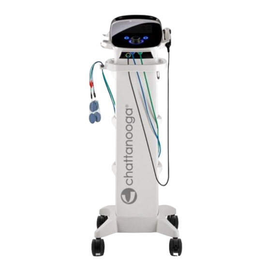
- Page 12 DEVICE DESCRIPTION 3.4. PRODUCT DESCRIPTION The Intelect® Legend 2 is a 2-channel or 4-channel electrotherapy and ultrasound combo system used with or without an optional Cart, allowing for the inclusion of a Vacuum module. This equipment is to be used only under the prescription and supervision of a licensed healthcare professional.
- Page 13 The components of the Intelect ® Legend 2 are shown below. INTELECT LEGEND 2 DOM: CART 6 BINS (15-1136) 81-5010 INTELECT LEGEND 2 2CH COMBO SET DOM 81-5011 INTELECT LEGEND 2 4CH COMBO SET DOM 2 CHANNEL COMBO DOM SET INCLUDES:...
- Page 14 DEVICE DESCRIPTION 3.7. SYSTEM DIMENSIONS AND SPECIFICATIONS Width Depth Height Weight (no battery) Intelect® Legend 2 Head Unit 2 Channel COMBO 34cm 35.5cm 15cm 3.1kg 4 Channel COMBO 34cm 35.5cm 19cm 3.7kg Cart configurations Cart (Safe working load 6.5kg) 48cm (MAX) 52cm (MAX) 96cm 10.1kg...
- Page 15 DEVICE DESCRIPTION 3.8. THERAPIES SPECIFICATIONS Output Power 3.8.1. Ultrasound Therapy Frequency 1 MHz; 3 MHz Duty Cycles 10%, 20%, 50%, Continuous Pulse Repetition Rate 16, 48, or 100 Hz Pulse duration: 1-31.25 ms Max (ON): 31.25 ms Min (OFF): 5 ms Unless otherwise specified, ultrasound controls accuracy is: ±...
- Page 16 DEVICE DESCRIPTION WAVEFORMS (CONTINUED) VMS™ TENS- Symmetrical Biphasic Advice on size and type of electrodes to be used is given in device GUI "treatment guidelines" feature Advice on size and type of electrodes to be used is given in device GUI "treatment guidelines" feature VMS is a symmetrical biphasic waveform with a 100 µsec interphase interval.
- Page 17 DEVICE DESCRIPTION WAVEFORMS (CONTINUED) IFC Premodulated (Traditional 2 Pole) VMS™ Burst Advice on size and type of electrodes to be used is given in device GUI "treatment guidelines" feature Advice on size and type of electrodes to be used is given in device GUI "treatment guidelines" feature VMS Burst is a symmetrical biphasic waveform delivered in a burst format.
- Page 18 DEVICE DESCRIPTION WAVEFORMS (CONTINUED) VMS™ FR High Voltage Pulsed Current (HVPC) The VMS-FR version of the VMS waveform is a physiologically based channel The High Voltage Pulsed Current (HVPC) has a very brief pulse duration interaction in which one channel stimulates the agonist and the other the characterized by two distinct peaks delivered at high voltage.
-
Page 19: User Interface
USER INTERFACE 4. USER INTERFACE 4.1. SOFTWARE VERSION AND SERIAL NUMBER 4.2. SCREEN DESCRIPTION 4.3. SETTINGS MENU 4.4. ADVANCED SETTINGS 4.5. SERVICE MENU 4.6. SOFTWARE UPDATE 4.7. PRINTSCREEN | Intelect Legend 2 - Service Manual DOMESTIC ®... -
Page 20: Settings Menu
Find the Serial Number of the control board and the software version when the device starts Version Update 04.10.00 First release 4.2. SCREEN DESCRIPTION 4.3. SETTINGS MENU Connect the Legend 2 with the application: Chattanooga Intelect Connect | Intelect Legend 2 - Service Manual DOMESTIC ®... -
Page 21: Advanced Settings
Clean Clean definitively the memory of deleted elements Clean Master Db UUID: Delete the identified computer when a synchronization with Chattanooga application has been done Ble Hw reset: Reset the Bluetooth Module if pairing issue with computer 4.5 SERVICE MENU On the “Display Unit Version Information”... -
Page 22: Printscreen
2. Maintain the “PLAY/PAUSE” Button down (①) and Push on “ON/OFF” Button (②) 2. Go to Intelect Legend 2 product tab 3. The screen is blinking 3. Complete the registration form to be informed 4. Go to the Settings menu about new product software version availability 5. -
Page 23: Maintenance Operation
MAINTENANCE OPERATION MAINTENANCE OPERATION 5.1. GENERAL 5.2. SPECIAL TOOLS, FIXTURES, & MATERIALS REQUIRED P24 5.3. EQUIPMENT REQUIRED 5.4. RECIPE FOR DEGASSED WATER 5.5. FULL FUNCTIONAL TESTS 5.6. US CALIBRATION REQUIREMENTS 5.7. US CALIBRATION PROCEDURE 5.8. CLEANING INSTRUCTION | Intelect Legend 2 - Service Manual DOMESTIC ®... - Page 24 Perform the tests found in this section to check Full wrong readings or test results. Always perform the Functionality of new Intelect Legend 2 and tests exactly as stated to ensure accurate results. accessories.
- Page 25 MAINTENANCE OPERATION US applicator servicing activities Repair Center Test after Action Equipment Comment with agreement repair FINAL TEST Cable + PCBA assy Watt meter Calibration replacement Required Calibration FINAL TEST Transducer Calibration Watt meter replacement Required Calibration FINAL TEST: Grip overmold Power test Watt meter replacement...
- Page 26 MAINTENANCE OPERATION Press “Next” to calibrate the power output to 1 MHz Press “Next”, dry the applicator and place it on the holder. Select “Hv nom” line and increase the power with the knob to read the “Target P” value on the power meter ...
- Page 27 MAINTENANCE OPERATION 5.8. CLEANING INSTRUCTION Cleaning the Intelect Legend 2 ® Disconnect everything from the power source, clean the system with a clean, lint-free cloth moistened with water and mild antibacterial soap. If more sterile cleaning is needed, use a cloth moistened with an antimicrobial cleaner.
-
Page 28: Troubleshooting
TROUBLESHOOTING TROUBLESHOOTING 6.1. NO POWER 6.2. SCREEN DEFAULT 6.3. FAN DEFAULT 6.4. BATTERY TEST 6.5. FAILURE DURING TREATMENT 6.6. ERRORS CODES | Intelect Legend 2 - Service Manual DOMESTIC ®... - Page 29 TROUBLESHOOTING TROUBLESHOOTING Before to release the device to the final customer, the Final Test must be done, passed at 100 % and registered in the doc ( Page 59 and 62) Unplug the device from the mains first ESD equipment is required to open the device 6.1.
- Page 30 TROUBLESHOOTING 6.2. SCREEN DEFAULT: If your device starts but the display stays black, white or can’t change IL2 TOP DISPLAY SUB ASSEMBLY SP-12-5002 Condition: Blue light on the ON/OFF button on the top of device The device starts, the 32 LEDS around the knob button are animated during 3 seconds and then you hear a bip after the end of the boot Verification: Black screen:...
- Page 31 TROUBLESHOOTING 6.4. BATTERY TEST 6.5. FAILURE DURING TREATMENT Problem during a Stim treatment Full charge : 3 h Full discharge Connect the stim cable to a load of 1kΩ and increase the intensity to 15 mA If it’s not good: replace the cable by a new one. On Electro-therapy: •...
-
Page 32: Repair Operation
REPAIR OPERATION 7. REPAIR OPERATION 7.1. TOOLS AND EQUIPMENTS TO REPAIR 7.2. BOTTOM OF THE DEVICE 7.3. SEPARATING TOP & LOWER ASSEMBLY 7.4. TOP SUB ASSEMBLY 7.5. LOWER SUB ASSEMBLY 7.6. REASSEMBLY 7.7. US APPLICATOR | Intelect Legend 2 - Service Manual DOMESTIC ®... - Page 33 REPAIR OPERATION 7.1. TOOLS AND EQUIPMENTS TO REPAIR Tools Accessories of Test Screwdriver Torx T20 Stim cables Screwdriver Torx T10 Screwdriver Torx T08 Screwdriver Flat 2 mm ESD Protection: ESD Matting • Earth Bonding Plug • US applicator Fabric Adjustable Wrist Strap •...
- Page 34 REPAIR OPERATION 7.2. BOTTOM OF THE DEVICE INSTALLATION OR REPLACEMENT OF BATTERY FRONT LIP 14-1086 G16 LI-ION BATTERY G16-4461-SP MOB2 FRONT LIP W Unscrew the battery door on the bottom of the device SP-14-3794 G16 FRONT LIP WHITE EXTENDED (2 screws) G16-1091-SP MOB2 FRONT LIP CLAMP B Remove the battery door...
- Page 35 REPAIR OPERATION 7.3. SEPARATING TOP & LOWER ASSEMBLY lower part. Repeat this on the other side. Unplug the device from the mains first ESD equipment is required to open the device G16-4101-SP MOB2 DEVICE HANDLE INTERNAL BLACK 14-1045-SP M4X12 TORX SCREW x 5 Unscrew the handle lock piece and remove the handle lock piece Turn the device upside down on a soft surface (to...
- Page 36 REPAIR OPERATION REPAIR OPERATION 7.4. TOP SUB ASSEMBLY ESD equipment is required to open the device CONTROL BOARD SP-G16-0011 IL2 CONTROL PCBA 14-1043-SP M3X8 TORX SCREW x 5 Back light: Open the connector before disconnecting the 1) To remove the control board, disconnect all ribbon cable horizontally.
- Page 37 REPAIR OPERATION DEVICE EXTERNAL SILVER KNOB / ENCODER G16-4011-SP MOB2 DEVICE EXTERNAL SILVER MOB2 KNOB EXTERNAL RING SILVER G16-4041 14-1041-SP KB30X8 PLASTIC TORX SCREW x 5 G16-4311-SP MOB2 KNOB RUBBER BLACK SP-14-1051 KB30X8 PLASTIC TORX SCREW x 5 14-1031-SP ENCODER GRAYHILL 62AG11-L0-020C SP-14-1036 G16 ENCODER FOAM 25MM x5 Unscrew these 4 screws (Torx T10)
- Page 38 REPAIR OPERATION CONTROL BUTTONS: PLAY and ON/OFF 7.5. LOWER SUB ASSEMBLY ESD equipment is required to open the device SP-12-5006 G16 BUTTON TOP SUB ASSY APPLICATOR HOLDER G16-4171-SP APPLICATOR HOLDER RIGHT W G16-4181-SP APPLICATOR HOLDER LEFT W 14-1043-SP M3X8 TORX SCREW x 5 Unscrew 2 screws/holder (Torx T10) Clamp the 2 clips of the button part and then push SP-14-1222...
- Page 39 REPAIR OPERATION POWER SUPPLY ON/OFF SWITCH SP-14-1123 POWER SUPPLY 24V100W 27151-SP SWITCH 20MM BK 14-1043-SP M3X8 TORX SCREW x 5 SP-14-1010 IL2 CABLE ROCKER TO POWER ENTRY SP-14-1055 IL2 CABLE ROCKER TO POWER SUPPLY SP-14-1055 IL2 CABLE ROCKER TO POWER SUPPLY SP-14-1057 IL2 CABLE POWER SUPPLY TO CTRL PCBA Disconnect the 4 rockers and press the 2 plastic tabs to...
- Page 40 REPAIR OPERATION COMBO 2 CH LOWER SUB ASSEMBLY COMBO 4 CH LOWER SUB ASSEMBLY G16-0021 IL2 STIM PCBA SP-G16-0021 IL2 STIM PCBA SP-G16-0031 IL2 ULTRASOUND PCBA G16-0031 IL2 ULTRASOUND PCBA SP-14-3797 IL2 US-STIM RIBBON CABLE 14-3798 IL2 2CH US-STIM RIBBON CABLE G16-2011-SP MOB2 PCB METAL SPACER 18 MM G16-2011-SP...
- Page 41 REPAIR OPERATION CONNECTORS PCBA FRONT PANEL COMBO 14-1040-SP KB30X6 PLASTIC TORX SCREW x 5 SP-G16-0052 G16 CONNECTORS PCBA SP-G16-4057 IL2 2CH FRONT PANEL BLACK SP-14-3792 IL2 4CH FRONT PANEL BLACK G16-0053 IL2 4CH CONNECTORS PCBA SP-G16-4241 G16 LIGHT PIPE CYAN US-L x5 SP-G16-4251 G16 LIGHT PIPE CYAN US-R x5 Unscrew the board (4 x Torx T10)
- Page 42 EXPLODED VIEWS AND SERVICE PARTS LISTS REPAIR OPERATION 7.6. REASSEMBLY and VISUAL CHECK Ensure all cables are clear of the side wall edges of Unplug the device from the mains first the two enclosures and center post. ESD equipment is required to open the device Remove all dust or other parts which could have moved inside the device before closing.
-
Page 43: Reassembly
EXPLODED VIEWS AND SERVICE PARTS LISTS REPAIR OPERATION 7.7. US APPLICATOR REASSEMBLY ESD equipment is required to open the device. Insert the PCB inside the grip in the rails and push the board to the end Unscrew the transducer. Screw the plastic part to the grip and check if the 2 O-rings stay in right position. -
Page 44: Final Test
EXPLODED VIEWS AND SERVICE PARTS LISTS FINAL TEST FINAL TEST 8.1. LIST OF MATERIAL 8.2. SETUP FOR FINAL TEST 8.3. FINAL TEST IL2 8.4. FINAL TEST US APPLICATOR | Intelect Legend 2 - Service Manual DOMESTIC ®... - Page 45 EXPLODED VIEWS AND SERVICE PARTS LISTS FINAL TEST 8.1. List of Material for Final test 2 x G16 Test Load (14-9706-2) 1 x Standard multimeter 1 x G16 battery (PN = 14-1086) 1 x Custom Power cable Type C13 1 x STIM cables set (PN=70010) 1 x STIM cables set (PN=70011) 2 x MD Box (PN=14-9709) 6 bananas cables with protection (2 Black, 2 Red, 1 Yellow, 1 Green)
- Page 46 EXPLODED VIEWS AND SERVICE PARTS LISTS FINAL TEST 8.2. Setup for final test Install the battery into the battery cavity of the • Connect the 1st MD Box between the red banana device. cable from the Custom power cord to the IN red connector of the MD Box and the black banana cable from the Custom power cord to the IN black connector of the MD Box...
- Page 47 EXPLODED VIEWS AND SERVICE PARTS LISTS FINAL TEST 8.3. FINAL TEST INTELECT LEGEND 2 Use a test US applicator Press “Beat frequency sweep” to obtain ON. The Stim cables must be connected on a load (1kΩ) Use the G16 test load box (PN 14-9706-2) Print the tracker sheet (Page 61) ...
- Page 48 EXPLODED VIEWS AND SERVICE PARTS LISTS FINAL TEST Set the multimeter to V AC and read the value, Ultrasound and User Interface you must have a value between 1.5V and 4V, after Press the “Ultrasound” icon. stabilization. After set the G16 Test Load switch COMBO to “OFF”.
- Page 49 EXPLODED VIEWS AND SERVICE PARTS LISTS FINAL TEST You should have the Ultrasound status channel Select the field intensity and increase again with “Running”. the knob until 2.0 W/Cm2. Let the program “Running” for 15 seconds and ...
- Page 50 EXPLODED VIEWS AND SERVICE PARTS LISTS FINAL TEST Electrotherapy and User Interface Select the CH2. Press the “CH1” icon. Press on the “IFC-2p” for INTL or “Premod” for DOM The following screen is displayed, on screen, press on “Sym Biph.”...
- Page 51 EXPLODED VIEWS AND SERVICE PARTS LISTS FINAL TEST Press on intensity button and increase the ONLY FOR THE LEGEND 2 4 CH • current with the knob for two complete rounds (> Select the CH3. 5mA), then press the “Play” button. •...
- Page 52 EXPLODED VIEWS AND SERVICE PARTS LISTS FINAL TEST “Premod” for DOM • You should have the CH4 status channel “Running”. For Legend 2 DOM only, scroll down to “CC/CV” to change the “Intensity CH2” from V to mA Check if the 4 LED around the connectors are ON and blinking.
- Page 53 EXPLODED VIEWS AND SERVICE PARTS LISTS FINAL TEST Simulation of Electrode fault Remove the Electrotherapy connector 2 from the device, a warning is displayed on the channel box 2. Remove the Electrotherapy connector 1 from the device, a warning is displayed on the channel box 1. ...
- Page 54 EXPLODED VIEWS AND SERVICE PARTS LISTS FINAL TEST ONLY FOR THE LEGEND 2 4 CH Remove the Electrotherapy connector 4 from the device, a warning is displayed on the channel box 4 Remove the Electrotherapy connector 3 from the device, a warning is displayed on the channel box 3 ...
- Page 55 EXPLODED VIEWS AND SERVICE PARTS LISTS FINAL TEST AC main leakage current • Set the multimeter to V DC and V AC, then read the values after stabilization. • Remove the red and black cables on the G16 Test Load and put it on the OUT of a 1 MD BOX connected to the Custom power cord.
- Page 56 EXPLODED VIEWS AND SERVICE PARTS LISTS FINAL TEST Total patient leakage • Remove the black connector of IN (MD Box). After, connect it over the red banana cable, connected to the black connector of STIM CH1 (Down G16 Test Load). ...
- Page 57 EXPLODED VIEWS AND SERVICE PARTS LISTS FINAL TEST Battery detection (test optional) Visual inspection Screen and Sounds Switch off the power line. Press the “sys “icon. Verify that the battery logo change, before , after ,(there is no more the symbol of ...
- Page 58 EXPLODED VIEWS AND SERVICE PARTS LISTS FINAL TEST 8.3.1. Tracker sheet for Intelect LEGEND 2 Final Test Procedure ⎵ ⎵ ⎵ ⎵ ⎵ ⎵ ⎵ ⎵ ⎵ 1. Serial Number (S/N) Done ⎵⎵.⎵⎵.⎵⎵ 2. Software Version: Done ( ⎵ ⎵ ⎵ ⎵ ) 3.
- Page 59 EXPLODED VIEWS AND SERVICE PARTS LISTS FINAL TEST Verify the LED is light continuously in BLUE, 8.4. ULTRASOUND APPLICATOR Check Pass/Fail the tracker sheet §4 Print the tracker sheet (P61) • Pause the treatment Note on this tracker sheet the Serial number and •...
- Page 60 EXPLODED VIEWS AND SERVICE PARTS LISTS Verify the wattmeter indicates 0 W, tare if necessary Select 1MHz frequency Set the power to min value (0.1 W) and start the treatment Verify the power is in the limit +/-15% (find value in tab) Set the power to max value Verify the power is in the limit +/-15% (find value in...
- Page 61 EXPLODED VIEWS AND SERVICE PARTS LISTS EXPLODED VIEWS and SERVICE PART LISTS 8.4.1. Tracker sheet for US Applicator Final Test Procedure ⎵ ⎵ ⎵ ⎵ ⎵ ⎵ ⎵ ⎵ ⎵ 1. Serial Number (S/N) Done ⎵⎵.⎵⎵.⎵⎵ 2. Size of applicator : 1 cm²...
-
Page 62: Exploded Views And Service Part Lists
EXPLODED VIEWS AND SERVICE PARTS LISTS EXPLODED VIEWS and SERVICE PART LISTS 8. EXPLODED VIEWS AND SERVICE PART LISTS 8.1. INTELECT LEGEND 2 8.2. INTELECT LEGEND 2 TOP ASSEMBLY 8.3. TOP DISPLAY SUB ASSEMBLY 8.4. LOWER SUB ASSEMBLY 8.4.1. COMBO 2CH LOWER SUB ASSEMBLY 8.4.2. - Page 63 SERVICE PART MOB2 APPLICATOR HOLDER LEFT W G16-4171-SP SERVICE PART MOB2 APPLICATOR HOLDER RIGHT W REFER P 67 INTELECT LEGEND 2 LOWER ASSEMBLY COMMON PARTS REFER P 69 INTELECT LEGEND 2 LOWER ASSEMBLY 2CH REFER P 71 INTELECT LEGEND 2 LOWER ASSEMBLY 4 CH...
- Page 64 EXPLODED VIEWS AND SERVICE PARTS LISTS EXPLODED VIEWS and SERVICE PART LISTS 9.2. INTELECT LEGEND 2 TOP ASSEMBLY ITEM N° Service Part n° Description G16-4311-SP SERVICE PART MOB2 KNOB RUBBER BLACK G16-4041-SP SERVICE PART MOB2 KNOB EXTERNAL RING SILVER G16-4031-SP...
- Page 65 EXPLODED VIEWS AND SERVICE PARTS LISTS EXPLODED VIEWS and SERVICE PART LISTS TOP DISPLAY SUB ASSEMBLY: SP-12-5002 ITEM N° Service Part n° Description SP-12-5006 SERVICE PART G16 BUTTON TOP SUB ASSEMBLY G16-4451-SP SERVICE PART MOB2 LED DIFFUSER KNOB 14-1041-SP SERVICE PART KB30X8 PLASTIC TORX SCREW x 5 | Intelect Legend 2 - Service Manual DOMESTIC ®...
- Page 66 EXPLODED VIEWS AND SERVICE PARTS LISTS EXPLODED VIEWS and SERVICE PART LISTS 9.3. LOWER SUB ASSEMBLY: COMMON PARTS All these parts are the same in the 2 versions of the Intelect Legend 2: 2 CH 4 CH | Intelect Legend 2 - Service Manual DOMESTIC ®...
- Page 67 EXPLODED VIEWS AND SERVICE PARTS LISTS EXPLODED VIEWS and SERVICE PART LISTS ITEM N° Service part n° Description 14-1046-SP SERVICE PART M4X35 TORX SCREW x 5 SP-14-1222 SERVICE PART IL2 FAN SP-14-1033 SERVICE PART IL2 INTERNAL VACUUM 10PINS RIBBON CABLE 14-1040-SP SERVICE PART KB30X6 PLASTIC TORX SCREW x 5 G16-1091-SP...
-
Page 68: Combo 2Ch Lower Sub Assembly
EXPLODED VIEWS AND SERVICE PARTS LISTS EXPLODED VIEWS and SERVICE PART LISTS COMBO 2CH LOWER SUB ASSEMBLY 9.3. 1. | Intelect Legend 2 - Service Manual DOMESTIC ®... - Page 69 EXPLODED VIEWS AND SERVICE PARTS LISTS EXPLODED VIEWS and SERVICE PART LISTS ITEM N° Service part n° Description SP-G16-4153 SERVICE PART IL2 2CH MAIN BODY WHITE 14-1044-SP SERVICE PART M4X8 TORX SCREW x 5 G16-4461-SP SERVICE PART MOB2 FRONT LIP W SP-14-3798 SERVICE PART IL2 2CH US-STIM RIBBON CABLE SERVICE PART G16 GREEN LIGHT PIPE STIM 2 x5...
-
Page 70: Combo 4Ch Lower Sub Assembly
EXPLODED VIEWS AND SERVICE PARTS LISTS EXPLODED VIEWS and SERVICE PART LISTS COMBO 4CH LOWER SUB ASSEMBLY 9.3.2. | Intelect Legend 2 - Service Manual DOMESTIC ®... - Page 71 EXPLODED VIEWS AND SERVICE PARTS LISTS EXPLODED VIEWS and SERVICE PART LISTS ITEM N° Service part n° Description SP-14-3739 SERVICE PART IL2 4CH MAIN BODY WHITE SP-14-3794 SERVICE PART IL2 4CH FRONT LIP WHITE EXTENDED SP-14-3797 SERVICE PART IL2 4CH US-STIM RIBBON CABLE SP-14-3801 SERVICE PART IL2 ORANGE LIGHT PIPE STIM 3 x5 SP-14-3802...
-
Page 72: Applicator
EXPLODED VIEWS AND SERVICE PARTS LISTS EXPLODED VIEWS and SERVICE PART LISTS 9.4. US APPLICATOR ITEM N° Service part n° Description 28091-SP SERVICE PART G16 US APPLICATOR O RING 27040-SP2 SERVICE PART G16 US APPLICATOR PROBE HOLDER x5 27138-SP SERVICE PART SCREW M3X16MM PAN HD PHIL PLT x5 14-1085-SP SERVICE PART G16 US APPLICATOR PROBE SPRING x5 14-1060-SP... -
Page 73: Cart 6 Bins
EXPLODED VIEWS AND SERVICE PARTS LISTS EXPLODED VIEWS and SERVICE PART LISTS 9.5. CART 6 BINS : | Intelect Legend 2 - Service Manual DOMESTIC ®... - Page 74 EXPLODED VIEWS AND SERVICE PARTS LISTS EXPLODED VIEWS and SERVICE PART LISTS ITEM N° Service part n° Description SERVICE PART EXPERIA SCREW, # 12 X 5/8, PHIL HEAD x5 27208-SP SERVICE PART MOB2 CART TOP BODY WHITE G16-4191-SP SERVICE PART MOB2 CART TOP HANDLE OUTER WHITE G16-4201-SP 14-1049-SP SERVICE PART KB30X12 SCREW TORX DRIVE x 5...
- Page 75 EXPLODED VIEWS AND SERVICE PARTS LISTS EXPLODED VIEWS and SERVICE PART LISTS DJO LLC 5919 Sea Otter Pl Ste 200, Carlsbad California, 92010-6750 djoglobal.com | Intelect ® Legend 2 - Service Manual DOMESTIC...
Need help?
Do you have a question about the Intelect Legend 2 and is the answer not in the manual?
Questions and answers