
Subscribe to Our Youtube Channel
Related Manuals for Pickering 40-784A


Summary of Contents for Pickering 40-784A
- Page 1 40-784A User Manual PXI Microwave Multiplexer Modules pickeringtest.com Issue 2.4 June 2021...
- Page 2 © COPYRIGHT (2021) PICKERING INTERFACES. ALL RIGHTS RESERVED. No part of this publication may be reproduced, transmitted, transcribed, translated or stored in any form, or by any means without the written permission of Pickering Interfaces. Technical details contained within this publication are subject to change without notice.
- Page 3 Pickering Interfaces strives to fulfil all relevant environmental laws and regulations and reduce wastes and releases to the environment. Pickering Interfaces aims to design and operate products in a way that protects the environment and the health and safety of its employees, customers and the public. Pickering Interfaces endeavours to develop and manufacture products that can be produced, distributed, used and recycled, or disposed of, in a safe and environmentally friendly manner.
-
Page 4: Product Safety
If this product is heavy reference should be made to the safety instructions for provisions of lifting and moving. STATIC SENSITIVE To indicate that static sensitive devices are present and handling precautions should be followed. REED RELAY MODULE 40-110/115/120/125 MICROWAVE MULTIPLEXER MODULE 40-784A Page (IV) Page (IV) -
Page 5: Table Of Contents
Pre Operation Checks ............3.1 Hardware Installation ............3.2 Software Installation .............3.2 Testing Operation ..............3.3 Section 4 Programming Guide ..............4.1 Programming Options For Pickering PXI Modules ....4.1 Module Architecture ..............4.2 Programming The Module ............4.3 Section 5 Connector Information ..............5.1 Section 6 Trouble Shooting .................6.1 Section 7 Maintenance Information ............7.1... - Page 6 THIS PAGE INTENTIONALLY BLANK MICROWAVE MULTIPLEXER MODULE 40-784A Page (VI)
-
Page 7: Warnings And Cautions
Unused slots in the host chassis are populated with blanking plates to prevent access to user I/O signals that may be present. Blanking panels are available to order from Pickering in a variety of slot widths. If the product is not used in this manner for example by using an extender card then additional care must be taken to avoid contact with exposed signals. - Page 8 THIS PAGE INTENTIONALLY BLANK MICROWAVE MULTIPLEXER MODULE 40-784A Page (VIII)
- Page 9 Microwave Relay Solutions (Typically <10.5 ms) y LED Indication y VISA, IVI & Kernel Drivers Supplied for Windows y Supported by PXI, PXIe Hybrid and Pickering LXI Modular Chassis y 3 Year Warranty The 40-784A PXI microwave multiplexer modules have a characteristic impedance of 50 Ω...
- Page 10 VSWR: <1:1.2 (0-3 GHz) <1:1.3 (3-6 GHz) Expected Life (low power): >10 million operations per position guaranteed (typically >25 million) Insertion Loss Repeatability: Within 0.01 dB Typical VSWR Plot for 6 GHz Versions pickeringtest.com MICROWAVE MULTIPLEXER MODULE 40-784A Page 1.2...
- Page 11 Typical Isolation (dB) Plot for 18 GHz Versions per position guaranteed (typically >25 million) Insertion Loss Repeatability: Within 0.025 dB Propagation Delay Variation (between channels): <1 ps Typical VSWR Plot for 18 GHz Versions pickeringtest.com MICROWAVE MULTIPLEXER MODULE 40-784A Page 1.3...
- Page 12 <1:1.4 (8-12.4 GHz) <1:1.5 (12.4-18 GHz) <1:1.6 (18-26.5 GHz) Expected Life (low power): >10 million operations per position guaranteed (typically >25 million) Insertion Loss Repeatability: Within 0.035 dB Typical VSWR Plot for 26.5 GHz Versions pickeringtest.com MICROWAVE MULTIPLEXER MODULE 40-784A Page 1.4...
- Page 13 <1:1.5 (12.4-18 GHz) <1:1.7 (18-26.5 GHz) <1:2.2 (26.5-40 GHz) Expected Life (low power): >2 million operations per position guaranteed (typically >5 million) Insertion Loss Repeatability: Within 0.05 dB Typical VSWR Plot for 40 GHz Versions pickeringtest.com MICROWAVE MULTIPLEXER MODULE 40-784A Page 1.5...
- Page 14 • 40 GHz versions - 50 Ω SMA-2.9.connectors. All modules are fully CE compliant and meet applicable EU directives: Low-voltage safety EN61010-1:2010, EMC Immunity EN61326-1:2013, Emissions EN55011:2009+A1:2010. 40-784A Single SP6T 40-784A Dual SP4T Microwave Multiplexer Microwave Multiplexer pickeringtest.com MICROWAVE MULTIPLEXER MODULE 40-784A Page 1.6...
- Page 15 40-784A-003 40-784A-023 40-784A-033 40-784A-043 Custom Configurations Pickering can also offer mixed configurations of SP4T and SP6T multiplexers with a mix of bandwidths as outlined in the table below. Please contact the sales office with your requirements. Frequency Configuration MUX Position 1 6 GHz, 18 GHz, 26.5 GHz or 40 GHz...
- Page 16 We provide a full range of supporting cable and connector solutions for all our switching products—20 connector families with 1200+ products. We offer everything from simple mating connectors to complex cables assemblies and terminal blocks. All assemblies are manufactured by Pickering and are guaranteed to mechanically and electrically mate to our modules. Connectors & Backshells...
- Page 17 Supporting Products & Software Microwave Multiplexer, 40-784A Programming Pickering provide kernel, IVI and VISA (NI & Keysight) drivers which are compatible with all Microsoft supported versions of Windows and popular older versions. For a list of all supporting operating systems, please see: pickeringtest.com/os The VISA driver is also compatible with Real-Time Operating Systems such as LabVIEW RT.
- Page 18 SECTION 1 - TECHNICAL SPECIFICATION pickering THIS PAGE INTENTIONALLY BLANK MICROWAVE MULTIPLEXER MODULE 40-784A Page 1.10...
-
Page 19: Functional Description
+12V LED INDICATORS U5 AND U6 RELAY DRIVER PCI BRIDGE CONFIGURATION BANK 2 1 2 3 4 5 6 LED INDICATORS Figure 2.1 - Microwave Multiplexer Module 40-784A: Functional Block Diagram (Dual Bank Version) MICROWAVE MULTIPLEXER MODULE 40-784A Page 2.1... - Page 20 SECTION 2 - TECHNICAL DESCRIPTION pickering THIS PAGE INTENTIONALLY BLANK MICROWAVE MULTIPLEXER MODULE 40-784A Page 2.2...
-
Page 21: Installation
Modular products require installation in a suitable PXI/LXI chassis. The module is designed for indoor use only. PREOPERATION CHECKS (UNPACKING) 1. Check the module for transport damage and report any damage immediately to Pickering Interfaces. Do not attempt to install the product if any damage is evident. -
Page 22: Hardware Installation
For a system comprising more than one chassis, turn ON the last chassis in the system followed by the penultimate, etc, and finally turn ON the external controller or chassis containing the system controller. 9. For Pickering Interfaces modular LXI installation there is no requirement to use any particular power up sequence. -
Page 23: Testing Operation
Figure 3.2 - General Soft Front Panel Icon A selector panel will appear, listing all installed Pickering PCI, PXI or LXI switch cards and resistor cards. Click on the card you wish to control, and a graphical control panel is presented allowing operation of the card. - Page 24 SECTION 3 - INSTALLATION pickering THIS PAGE INTENTIONALLY BLANK MICROWAVE MULTIPLEXER MODULE 40-784A Page 3.4...
-
Page 25: Programming Guide
SECTION 4 - PROGRAMMING GUIDE PROGRAMMING OPTIONS FOR PICKERING INTERFACES PXI MODULES For information on the installation and use of drivers and the programming of Pickering’s products in various software environments, please refer to the Software User Manual. This is available as a download from: https://www.pickeringtest.com/support/software-drivers-and-downloads... -
Page 26: Module Architecture
ComC ChC4 ComB ChB4 ChB5 ChC5 ChB6 ChC6 Single SP6T Dual SP6T Triple SP6T Figure 4.1 - The 40-784A Module Switching Architectures - 6-Channel Versions MUX Bank 1 ChA1 (Ch1) ChA2 (Ch2) ComA ChA3 (Ch3) ChA4 (Ch4) MUX Bank 1... -
Page 27: Programming The Module
Com to Ch3 comB chB3 Com to Ch3 comB chB3 Com to Ch4 comB chB4 Com to Ch4 comB chB4 Com to Ch5 comB chB5 ─ ─ ─ Com to Ch6 comB chB6 ─ ─ ─ MICROWAVE MULTIPLEXER MODULE 40-784A Page 4.3... - Page 28 ─ ─ ─ Here are examples of using the drivers with the 40-784A Multiplexer. Using PILPXI To enable a signal path the user could use the simple OpBit command OpBit DWORD sub_unit = 1; // Select Bank 1 PIL_OpBit( card_num, sub_unit, 1, 1);...
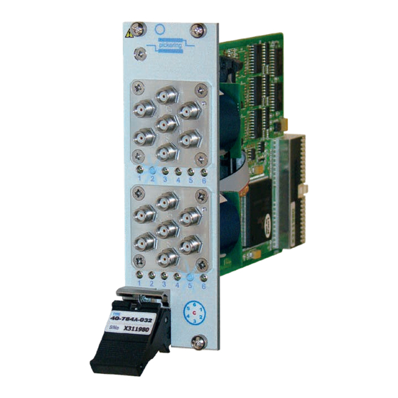
- Page 29 Figure 5.1 - Microwave Multiplexer Module 40-784A: Connector Positions For Single, Dual and Triple SP6T Versions NOTE 1: Only the correct connector series should be mated with these modules. The 40-784A range uses SMA connectors for the 6GHz, 18GHz and 26.5GHz modules, and SMA-2.9 connectors for the 40GHz Modules.
- Page 30 The red text indicates the physical connector numbering displayed on the front panel of the module. NOTE 1: Only the correct connector series should be mated with these modules. The 40-784A range uses SMA connectors for the 6GHz, 18GHz and 26.5GHz modules, and SMA-2.9 connectors for the 40GHz Modules.
-
Page 31: Trouble Shooting
PCI configuration, highlighting any potential configuration problems. Specific details of all installed Pickering switch cards are included. All the installed Pickering switch cards should be listed in the “Pilpxi information” section - if one or more cards is missing it may be possible to determine the reason by referring to the PCI configuration dump contained in the report, but interpretation of this information is far from straightforward, and the best course is to contact Pickering support: support@pickeringtest.com, if possible... - Page 32 SECTION 6 - TROUBLE SHOOTING pickering THIS PAGE INTENTIONALLY BLANK MICROWAVE MULTIPLEXER MODULE 40-784A Page 6.2...
-
Page 33: Maintenance Information
For PXI modules which are supported in one of Pickering Interfaces’ Modular LXI Chassis (such as the 60-102B and 60-103B) no module software update is required. If the module was introduced after the LXI chassis was manufactured the module may not be recognized, in this case the chassis firmware may need upgrading. - Page 34 SECTION 7 - MAINTENANCE INFORMATION pickering THIS PAGE INTENTIONALLY BLANK MICROWAVE MULTIPLEXER MODULE 40-784A Page 7.2...
Need help?
Do you have a question about the 40-784A and is the answer not in the manual?
Questions and answers