
Related Manuals for Pickering 40-682A


Summary of Contents for Pickering 40-682A
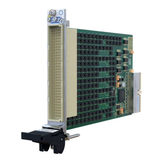
- Page 1 40-682A User Manual PXI Solid State Versatile Multiplexer Module pickeringtest.com Issue 2.3 November 2021...
- Page 2 © COPYRIGHT (2021) PICKERING INTERFACES. ALL RIGHTS RESERVED. No part of this publication may be reproduced, transmitted, transcribed, translated or stored in any form, or by any means without the written permission of Pickering Interfaces. Technical details contained within this publication are subject to change without notice.
- Page 3 Pickering Interfaces strives to fulfil all relevant environmental laws and regulations and reduce wastes and releases to the environment. Pickering Interfaces aims to design and operate products in a way that protects the environment and the health and safety of its employees, customers and the public. Pickering Interfaces endeavours to develop and manufacture products that can be produced, distributed, used and recycled, or disposed of, in a safe and environmentally friendly manner.
-
Page 4: Product Safety
If this product is heavy reference should be made to the safety instructions for provisions of lifting and moving. STATIC SENSITIVE To indicate that static sensitive devices are present and handling precautions should be followed. REED RELAY MODULE 40-110/115/120/125 SOLID STATE VERSATILE MULTIPLEXER MODULE 40-682A Page (IV) Page (IV) -
Page 5: Table Of Contents
Programming Options for PXI Modules ......4.1 Programming The 40-682A ...........4.2 Programming Lookup Tables ..........4.7 Section 5 Connector Information ..............5.1 Section 6 Trouble Shooting .................6.1 Section 7 Maintenance Information ............7.1 Relay Lookup Tables .............7.1 SOLID STATE VERSATILE MULTIPLEXER MODULE 40-682A Page (V) - Page 6 THIS PAGE INTENTIONALLY BLANK SOLID STATE VERSATILE MULTIPLEXER MODULE 40-682A Page (VI)
-
Page 7: Warnings And Cautions
Not to be used in safety critical circuits, refer to the Pickering Interfaces’ terms & conditions of sale. This module must not be used for the switching of Mains Circuits. For the switching of voltages up to the module’s full specification, Secondary Circuit power supplies and the Device Under Test must... - Page 8 • For suitably equipped products in the event of an emergency press the red “emergency stop” button situated on the front of the unit. SOLID STATE VERSATILE MULTIPLEXER MODULE 40-682A Page (VIII) 2 AMP 1-POLE UHD MATRIX MODULES 40-575 / 576 / 577 / 578 / 579...
-
Page 9: Technical Specification
Supported by eBIRST The 40-682A can be operated as a conventional multiplexer eBIRST test tools simplify fault-finding by quickly testing with break-before-make action when a new channel is the system and graphically identifying the faulty relay. - Page 10 Com 5.2 40.2 41.1 Com 6.1 MUX6 Com 6.2 48.2 49.1 Com 7.1 MUX7 Com 7.2 56.2 57.1 Com 8.1 MUX8 Com 8.2 64.2 Functional Diagram of 40-682A Solid State Versatile Multiplexer pickeringtest.com SOLID STATE VERSATILE MULTIPLEXER MODULE 40-682A Page 1.2...
- Page 11 Start: 300kHz Stop: 1MHz Start: 300kHz Stop: 1MHz Insertion Loss Plot for 40-682A with 3 switches in path Insertion Loss Plot for 40-682A with 5 switches in path (between C1.1 and 1.1) (between 1.1 and 1.2) Start: 300kHz...
- Page 12 Specifications Solid State Verstatile MUX, 40-682A Relay Type Mechanical Characteristics The 40-682A is fitted with Solid State Switches. Single slot 3U PXI (CompactPCI card). 3D models for all versions in a variety of popular file Switching Specification formats are available on request.
- Page 13 During configuration setting, all relay control information is logged in a text file which can be re-used in a programming environment. Soft Front Panel for the 40-612A, 40-681A, 40-682A and 40-683A Very High Density Versatile Multiplexers pickeringtest.com SOLID STATE VERSATILE MULTIPLEXER MODULE 40-682A...
- Page 14 We provide a full range of supporting cable and connector solutions for all our switching products—20 connector families with 1200+ products. We offer everything from simple mating connectors to complex cables assemblies and terminal blocks. All assemblies are manufactured by Pickering and are guaranteed to mechanically and electrically mate to our modules. Connectors & Backshells...
- Page 15 Solid State Verstatile MUX, 40-682A Programming Pickering provide kernel, IVI and VISA (NI & Keysight) drivers which are compatible with all Microsoft supported versions of Windows and popular older versions. For a list of all supporting operating systems, please see: pickeringtest.com/os...
- Page 16 SECTION 1 - TECHNICAL SPECIFICATION pickering THIS PAGE INTENTIONALLY BLANK SOLID STATE VERSATILE MULTIPLEXER MODULE 40-682A Page 1.8...
-
Page 17: 40-682A Functional Description
SECTION 2 - TECHNICAL DESCRIPTION 40-682A Functional Description The 40-682A can be configured by the user to provide many different multiplexer configurations. This functional description provides an overview of these possibilities based on the functional diagram in Figure 2.1. MUX1... - Page 18 To 1 Pole Selection Switches Figure 2.2 - 40-682A Module: Output MUX 1 Pole Selection Switches Each of these switches allows the MUX to be set to be one pole or two pole, or allows the corresponding MUX output to be disconnected: 2 pole setting Series relays are closed and shunt switch is open.
- Page 19 Pole2 Switches Switches Figure 2.4 - 40-682A Module: Selecting Pole 1 or Pole 2 to Create a 1-Pole MUX Isolation Setting The output MUX can be disconnected by opening the series relays Note: Disconnection can also be set by using the Isolation Switches, however if the module is being set as a wide MUX then it may on some occasions be desirable to use this control to lower the capacitive loading on the MUX by disconnecting unwanted sections>...
- Page 20 Com 2 To 1 Pole Com 3 Selection Isolation Switches Switches Com 4 Com 5 Com 6 Com 7 Com 8 Figure 2.5 - 40-682A Module: Inter-Bank Connections - First Tier Switches SOLID STATE VERSATILE MULTIPLEXER MODULE 40-682A Page 2.4...
- Page 21 To 1 Pole Com 3 Selection Isolation Switches Switches Com 4 Com 5 Com 6 Com 7 Com 8 Figure 2.6 - 40-682A Module: Inter-Bank Connections - First and Second Tier Switches SOLID STATE VERSATILE MULTIPLEXER MODULE 40-682A Page 2.5...
- Page 22 Com 7.2 Com 8.1 Com 8.2 Figure 2.8 - 40-682A Module: Isolation Switches Very Wide MUXs It should be noted that the COM ports can be used as MUX outputs in some circumstances. Example: If COM 1 is used as the input and all output MUXs connected to it then COM2 to COM 8 can be used as additional MUX outputs by closing the interbank and isolation switches.
-
Page 23: Installation
Modular products require installation in a suitable PXI/LXI chassis. The module is designed for indoor use only. PREOPERATION CHECKS (UNPACKING) 1. Check the module for transport damage and report any damage immediately to Pickering Interfaces. Do not attempt to install the product if any damage is evident. -
Page 24: Hardware Installation
For a system comprising more than one chassis, turn ON the last chassis in the system followed by the penultimate, etc, and finally turn ON the external controller or chassis containing the system controller. 9. For Pickering Interfaces modular LXI installation there is no requirement to use any particular power up sequence. -
Page 25: Testing Operation
Figure 3.2 - General Soft Front Panel Icon A selector panel will appear, listing all installed Pickering PCI, PXI or LXI switch cards and resistor cards. Click on the card you wish to control, and a graphical control panel is presented allowing operation of the card. - Page 26 SECTION 3 - INSTALLATION pickering THIS PAGE INTENTIONALLY BLANK SOLID STATE VERSATILE MULTIPLEXER MODULE 40-682A Page 3.4...
-
Page 27: Programming Guide
SECTION 4 - PROGRAMMING PROGRAMMING OPTIONS FOR PICKERING INTERFACES PXI MODULES For information on the installation and use of drivers and the programming of Pickering’s products in various software environments, please refer to the Software User Manual. This is available as a download from: https://www.pickeringtest.com/support/software-drivers-and-downloads... - Page 28 MUXes of larger size, for example16x1, 24,1, 32x1 etc. It is also possible to use the 2-wires as individual inputs, changing a 2-wire 8x1 section into a 1-wire 16x1. In terms of sub-units, discussed briefly in the preceding section, the 40-682A contains 13 sub-units as follows: Sub-Unit...
- Page 29 // Select input 1 of first 16x1 MUX (1st bit on first 8x1 bank) PIL_OpBit(card, 1, 1, 1); // Select input 9 of first 16x1 MUX (1st bit on 2nd 8x1 bank) PIL_OpBit(card, 2, 1, 1); PIL_CloseSpecifiedCard(card); SOLID STATE VERSATILE MULTIPLEXER MODULE 40-682A Page 4.3...
- Page 30 // Select input 1 of first 16x1 MUX (1st bit on first 8x1 bank) pipx40_setChannelState(vi, 1, 1, 1); // Select input 9 of first 16x1 MUX (1st bit on 2nd 8x1 bank) pipx40_setChannelState(vi, 2, 1, 1); pipx40_close(vi); SOLID STATE VERSATILE MULTIPLEXER MODULE 40-682A Page 4.4...
- Page 31 The following configurations are provided in the pi40iv.ini driver configuration file in your installation. Use one of these strings in the InitWithOptions function. The format of the string is 40-682A-002-(pole)w(bank)/(channel)x1 as shown below:...
- Page 32 PRL101 PRL102 MUX8 Com 8.2 64.2 PRL57 TO PRL64 PRL104B Figure 4.1 - Relay Switching Schematic, programming sub-unit numbers are in blue, bit numbers within a sub-unit are in circled in red. SOLID STATE VERSATILE MULTIPLEXER MODULE 40-682A Page 4.6...
-
Page 33: Programming Lookup Tables
Bank 4, Channel 6 MUX(8)* Channel Bank 4, Channel 7 MUX(8)* Channel Bank 4, Channel 8 * For modules with multi-channel selection capability (“-M” ordering option) the sub-unit type will be “MUXM(8)” SOLID STATE VERSATILE MULTIPLEXER MODULE 40-682A Page 4.7... - Page 34 Bank 8, Channel 6 MUX(8)* Channel Bank 8, Channel 7 MUX(8)* Channel Bank 8, Channel 8 * For modules with multi-channel selection capability (“-M” ordering option) the sub-unit type will be “MUXM(8)” SOLID STATE VERSATILE MULTIPLEXER MODULE 40-682A Page 4.8...
- Page 35 Bank 5, interbank linking SWITCH(8) Interbank Linking Bank 5, interbank linking SWITCH(8) Interbank Linking Bank 7, interbank linking Note: Bank references listed above relate to an 8-bank configuration, for variants, the bank identifiers will change. SOLID STATE VERSATILE MULTIPLEXER MODULE 40-682A Page 4.9...
- Page 36 4 \ 8 8 \ 8 Note: The two individal channels from a single relay in 1-pole mode are selected by using the 1/2-pole & pole shorting relays detailed in Table 4.3. SOLID STATE VERSATILE MULTIPLEXER MODULE 40-682A Page 4.10...
- Page 37 4 \ 8 8 \ 8 Note: The two individal channels from a single relay in 1-pole mode are selected by using the 1/2-pole & pole shorting relays detailed in Table 4.3. SOLID STATE VERSATILE MULTIPLEXER MODULE 40-682A Page 4.11...
- Page 38 4 \ 8 8 \ 8 Note: The two individal channels from a single relay in 1-pole mode are selected by using the 1/2-pole & pole shorting relays detailed in Table 4.3. SOLID STATE VERSATILE MULTIPLEXER MODULE 40-682A Page 4.12...
- Page 39 4 \ 8 8 \ 8 Note: The two individal channels from a single relay in 1-pole mode are selected by using the 1/2-pole & pole shorting relays detailed in Table 4.3. SOLID STATE VERSATILE MULTIPLEXER MODULE 40-682A Page 4.13...
- Page 40 4 \ 8 8 \ 8 Note: The two individal channels from a single relay in 1-pole mode are selected by using the 1/2-pole & pole shorting relays detailed in Table 4.3. SOLID STATE VERSATILE MULTIPLEXER MODULE 40-682A Page 4.14...
- Page 41 4 \ 8 8 \ 8 Note: The two individal channels from a single relay in 1-pole mode are selected by using the 1/2-pole & pole shorting relays detailed in Table 4.3. SOLID STATE VERSATILE MULTIPLEXER MODULE 40-682A Page 4.15...
- Page 42 4 \ 8 127 128 8 \ 8 Note: The two individal channels from a single relay in 1-pole mode are selected by using the 1/2-pole & pole shorting relays detailed in Table 4.3. SOLID STATE VERSATILE MULTIPLEXER MODULE 40-682A Page 4.16...
- Page 43 4 \ 8 8 \ 8 Note: The two individal channels from a single relay in 1-pole mode are selected by using the 1/2-pole & pole shorting relays detailed in Table 4.3. SOLID STATE VERSATILE MULTIPLEXER MODULE 40-682A Page 4.17...
- Page 44 Note 1: Do NOT energise the 1-pole & 2-pole selection relays at the same time as applied channel signals will be shorted together. Note 2: The above 1-pole configurations assume that the .1 common pin(s) are being used on the front panel connector. SOLID STATE VERSATILE MULTIPLEXER MODULE 40-682A Page 4.18...
- Page 45 1-Pole selection 10 \ 8 2-Pole selection 11 \ 8 Isolation 9 \ 8 Note: The above 1-pole configurations assume that the .1 common pin(s) are being used on the front panel connector. SOLID STATE VERSATILE MULTIPLEXER MODULE 40-682A Page 4.19...
- Page 46 Note 1: Do NOT energise the 1-pole & 2-pole selection relays at the same time as applied channel signals will be shorted together. Note 2: The above 1-pole configurations assume that the .1 common pin(s) are being used on the front panel connector. SOLID STATE VERSATILE MULTIPLEXER MODULE 40-682A Page 4.20...
- Page 47 2-Pole selection 11 \ 8 Interbank Linking 13 \ 8 Isolation 9 \ 7 Note: The above 1-pole configurations assume that the .1 common pin(s) are being used on the front panel connector. SOLID STATE VERSATILE MULTIPLEXER MODULE 40-682A Page 4.21...
- Page 48 Note 1: Do NOT energise the 1-pole & 2-pole selection relays at the same time as applied channel signals will be shorted together. Note 2: The above 1-pole configurations assume that the .1 common pin(s) are being used on the front panel connector. SOLID STATE VERSATILE MULTIPLEXER MODULE 40-682A Page 4.22...
- Page 49 Interbank Linking 13 \ 7 Interbank Linking 13 \ 8 Isolation 9 \ 5 Note: The above 1-pole configurations assume that the .1 common pin(s) are being used on the front panel connector. SOLID STATE VERSATILE MULTIPLEXER MODULE 40-682A Page 4.23...
- Page 50 Note 1: Do NOT energise the 1-pole & 2-pole selection relays at the same time as applied channel signals will be shorted together. Note 2: The above 1-pole configurations assume that the .1 common pin(s) are being used on the front panel connector. SOLID STATE VERSATILE MULTIPLEXER MODULE 40-682A Page 4.24...
- Page 51 Interbank Linking 13 \ 7 Interbank Linking 13 \ 8 Isolation 9 \ 1 Note: The above 1-pole configurations assume that the .1 common pin(s) are being used on the front panel connector. SOLID STATE VERSATILE MULTIPLEXER MODULE 40-682A Page 4.25...
- Page 52 SECTION 4 - PROGRAMMING GUIDE pickering THIS PAGE INTENTIONALLY BLANK SOLID STATE VERSATILE MULTIPLEXER MODULE 40-682A Page 4.26...
- Page 53 40-682A Pin Designations - IVI Modes The 40-682A has a number of modes of operation when controlled through IVI where the MUX can be set to a specified configuration. The tables on the following pages apply to each of the IVI mode settings. For more information on the IVI modes see the IVI section in the programming chapter of this manual.
- Page 54 BANK 7 BANK 8 chH4 chH8 chH12 chH16 Figure 5.2 - Multiplexer Module 40-682A: IVI mode corresponding to 8-Bank, 16-Channel, 1-Pole pin designations. The pin designations shown correspond to the IVI port. SOLID STATE VERSATILE MULTIPLEXER MODULE 40-682A Page 5.2...
- Page 55 (2) chH4 (2) chH6 (2) chH8 (2) Figure 5.3 - Multiplexer Module 40-682A: IVI mode corresponding to 8-Bank, 8-Channel, 2-Pole pin designations. The pin designations shown correspond to the IVI port. SOLID STATE VERSATILE MULTIPLEXER MODULE 40-682A Page 5.3...
- Page 56 BANK 4 Figure 5.4 - Multiplexer Module 40-682A: IVI mode corresponding to 4-Bank, 32-Channel, 1-Pole pin designations. The pin designations shown correspond to the IVI port. SOLID STATE VERSATILE MULTIPLEXER MODULE 40-682A Page 5.4...
- Page 57 (2) chD14 (2) chD16 (2) chD16(2) BANK 4 Figure 5.5 - Multiplexer Module 40-682A: IVI mode corresponding to 4-Bank, 16-Channel, 2-Pole pin designations. The pin designations shown correspond to the IVI port. SOLID STATE VERSATILE MULTIPLEXER MODULE 40-682A Page 5.5...
- Page 58 Figure 5.6 - Multiplexer Module 40-682A: IVI mode corresponding to 2-Bank, 64-Channel, 1-Pole pin designations. The pin designations shown correspond to the IVI port. SOLID STATE VERSATILE MULTIPLEXER MODULE 40-682A Page 5.6...
- Page 59 (2) chB28 (2) chB30 (2) chB32 (2) Figure 5.7 - Multiplexer Module 40-682A: IVI mode corresponding to 2-Bank, 32-Channel, 2-Pole pin designations. The pin designations shown correspond to the IVI port. SOLID STATE VERSATILE MULTIPLEXER MODULE 40-682A Page 5.7...
- Page 60 Figure 5.8 - Multiplexer Module 40-682A: IVI mode corresponding to 1-Bank, 128-Channel, 1-Pole pin designations. The pin designations shown correspond to the IVI port. SOLID STATE VERSATILE MULTIPLEXER MODULE 40-682A Page 5.8...
- Page 61 (2) chA60 (2) chA62 (2) chA64 (2) Figure 5.9 - Multiplexer Module 40-682A: IVI mode corresponding to 1-Bank, 64-Channel, 2-Pole pin designations. The pin designations shown correspond to the IVI port. SOLID STATE VERSATILE MULTIPLEXER MODULE 40-682A Page 5.9...
- Page 62 SECTION 5 - CONNECTOR INFORMATION pickering THIS PAGE INTENTIONALLY BLANK SOLID STATE VERSATILE MULTIPLEXER MODULE 40-682A Page 5.10...
-
Page 63: Trouble Shooting
PCI configuration, highlighting any potential configuration problems. Specific details of all installed Pickering switch cards are included. All the installed Pickering switch cards should be listed in the “Pilpxi information” section - if one or more cards is missing it may be possible to determine the reason by referring to the PCI configuration dump contained in the report, but interpretation of this information is far from straightforward, and the best course is to contact Pickering support: support@pickeringtest.com, if possible... - Page 64 SECTION 6 - TROUBLE SHOOTING pickering SOLID STATE VERSATILE MULTIPLEXER MODULE 40-682A Page 6.2...
-
Page 65: Maintenance Information
For PXI modules which are supported in one of Pickering Interfaces’ Modular LXI Chassis (such as the 60-102B and 60-103B) no module software update is required. If the module was introduced after the LXI chassis was manufactured the module may not be recognized, in this case the chassis firmware may need upgrading. - Page 66 33, 34, 35, 36, 37, 38, 39, 40, 41, 42, 43, 44, 45, 46, 47, 48 96, 97, 101, 102 49, 50, 51, 52, 53, 54, 55, 56, 57, 58, 59, 60, 61, 62, 63, 64 SOLID STATE VERSATILE MULTIPLEXER MODULE 40-682A Page 7.2...
- Page 67 1-pole mode depending on where the signal originates. The common (c) relay is used to route the .2 MUX signals to the .1 common output pin on the module connector and can remain de-energised when signals from the .1 sections are used in 1-pole mode. SOLID STATE VERSATILE MULTIPLEXER MODULE 40-682A Page 7.3...
- Page 68 SECTION 7 - MAINTENANCE INFORMATION pickering 104A 104B SPARE SPARE 100B 100A Figure 7.1 - Solid State Versatile Multiplexer Module 40-682A: Relay Positions SOLID STATE VERSATILE MULTIPLEXER MODULE 40-682A Page 7.4...
Need help?
Do you have a question about the 40-682A and is the answer not in the manual?
Questions and answers