
Related Manuals for Pickering 40-558


Summary of Contents for Pickering 40-558
- Page 1 40-558 User Manual PXI BRIC™ Multi-Slot Ultra High Density Matrix Module pickeringtest.com Issue 2.0 June 2022...
- Page 2 © COPYRIGHT (2022) PICKERING INTERFACES. ALL RIGHTS RESERVED. No part of this publication may be reproduced, transmitted, transcribed, translated or stored in any form, or by any means without the written permission of Pickering Interfaces. Technical details contained within this publication are subject to change without notice.
- Page 3 Pickering Interfaces strives to fulfil all relevant environmental laws and regulations and reduce wastes and releases to the environment. Pickering Interfaces aims to design and operate products in a way that protects the environment and the health and safety of its employees, customers and the public. Pickering Interfaces endeavours to develop and manufacture products that can be produced, distributed, used and recycled, or disposed of, in a safe and environmentally friendly manner.
-
Page 4: Product Safety
If this product is heavy reference should be made to the safety instructions for provisions of lifting and moving. STATIC SENSITIVE To indicate that static sensitive devices are present and handling precautions should be followed. REED RELAY MODULE 40-110/115/120/125 PXI BRIC MULTI-SLOT ULTRA HIGH DENSITY MATRIX (40-558) Page (IV) Page (IV) -
Page 5: Table Of Contents
Relay Look-up Tables - X8 Configurations ......7.23 Relay Look-up Tables - X12 Configurations ....... 7.44 Relay Look-up Tables - X16 Configurations ....... 7.65 BRIC12 Removal/Replacement ..........7.86 Daughtercard Removal/Replacement ........7.88 PXI BRIC MULTI-SLOT ULTRA HIGH DENSITY MATRIX (40-558) Page (V) - Page 6 THIS PAGE INTENTIONALLY BLANK PXI BRIC MULTI-SLOT ULTRA HIGH DENSITY MATRIX (40-558) Page (VI)
-
Page 7: Warnings And Cautions
Not to be used in safety critical circuits, refer to the Pickering Interfaces’ terms & conditions of sale. This module must not be used for the switching of Mains Circuits. For the switching of voltages up to the module’s full specification, Secondary Circuit power supplies and the Device Under Test must... - Page 8 • For suitably equipped products in the event of an emergency press the red “emergency stop” button situated on the front of the unit. 2 AMP 1-POLE UHD MATRIX MODULES 40-575 / 576 / 577 / 578 / 579 PXI BRIC MULTI-SLOT ULTRA HIGH DENSITY MATRIX (40-558) Page (VIII) Page (VIII)
-
Page 9: Technical Specification
BRIC PXI Reed Relay Matrices Spare relays are included with the module to allow easy maintenance with minimum downtime. All reed relays are The 40-558 PXI BRIC is an ultra high density matrix manufactured by our Relay Division: pickeringrelay.com module available in 2, 4, 8 or 12-slot sizes suitable for high The BRIC’s internal high performance screened analog... - Page 10 BRIC Ultra High Density Matrix, 40-558 Pickering’s Range of BRIC Matrix Modules Pickering Reed Relay BRIC Advantages 40-558 - 1-Pole Matrix - 0.5 A Reed Relay • Only uses the highest quality instrument grade reed relays – BRIC2 Up to 252x6, 192x8, 126x12 or 96x16 be wary of inferior copies.
- Page 11 Analog Bus A Y Connections - A Analog Bus B Y Connections - B x8 Configurations Architecture diagrams for x6 and x8 configurations of the 40-558 range showing how the matrix daughter cards are interconnected with dual analog buses. Isolation pickeringtest.com Switches...
- Page 12 Analog Bus Y Connections x16 Configurations Architecture diagrams for x12 and x16 configurations of the 40-558 range showing how the matrix daughter cards are interconnected with a single analog bus. Analog Bus The Y-buses of the 40-558 daughter cards are linked via the analog bus on the BRIC backplane.
- Page 13 100 kHz: -40 dB 1 MHz: -30 dB 10 MHz -15 dB Isolation (typical): 10 kHz: 65 dB 100 kHz: 60 dB 1 MHz: 55 dB 10 MHz 30 dB pickeringtest.com PXI BRIC MULTI-SLOT ULTRA HIGH DENSITY MATRIX (40-558) Page 1.5...
- Page 14 BRIC Ultra High Density Matrix, 40-558 Width and Dimensions Maximum Crosspoint Count Two, four, eight or twelve-slot 3 U PXI module The 40-558 has a suggested maximum number of (CompactPCI). simultaneously operated crosspoints: • 50 per BRIC2 3D models for these modules in a variety of popular file formats are available on request.
- Page 15 1092x6 Matrix -1092x6 -630x12 630x12 Matrix -1176x6 1176x6 Matrix -672x12 672x12 Matrix -1260x6 1260x6 Matrix -714x12 714x12 Matrix -1344x6 1344x6 Matrix -756x12 756x12 Matrix -1428x6 1428x6 Matrix -1512x6 1512x6 Matrix pickeringtest.com PXI BRIC MULTI-SLOT ULTRA HIGH DENSITY MATRIX (40-558) Page 1.7...
- Page 16 -544x16 544x16 Matrix -576x16 576x16 Matrix Mating Connectors & Cabling For connection accessories for the 40-558 module please refer to the 90-015D 68-pin male micro-D and 90-019D 100-pin female micro-D Accessories data sheets where a complete list and documentation can be found for accessories, or refer to the Connection Solutions catalog.
- Page 17 We provide a full range of supporting cable and connector solutions for all our switching products—20 connector families with 1200+ products. We offer everything from simple mating connectors to complex cables assemblies and terminal blocks. All assemblies are manufactured by Pickering and are guaranteed to mechanically and electrically mate to our modules. Connectors & Backshells...
- Page 18 BRIC Ultra High Density Matrix, 40-558 Programming Pickering provide kernel, IVI and VISA (NI & Keysight) drivers which are compatible with all Microsoft supported versions of Windows and popular older versions. For a list of all supporting operating systems, please see: pickeringtest.com/os...
-
Page 19: Technical Description
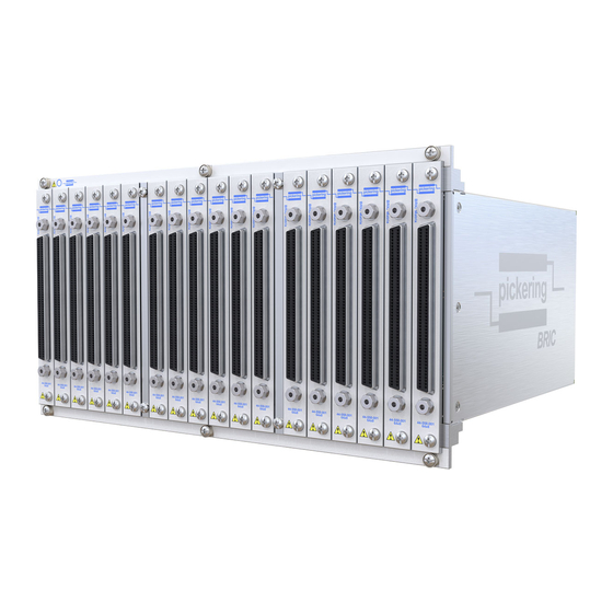
The chassis is provided with cooling slots, top and bottom. The backplane provides mounting for the connectors (into which the daughtercards plug) and control logic. Figure 2.1 - Fully Populated 40-558 BRIC12 Matrix Module FUNCTIONAL DESCRIPTION The BRIC module is connected to the host chassis via a Compact PCI connector mounted on the backplane in PXI slot position 1. - Page 20 Note: The 12-Slot Backplane is fitted with a second Compact PCI Bus Connector which is used for power only. Figure 2.2 - 40-558 BRIC Module x6 & x8 Configurations: Functional Block Diagram PXI BRIC MULTI-SLOT ULTRA HIGH DENSITY MATRIX (40-558)
- Page 21 Note: The 12-Slot Backplane is fitted with a second Compact PCI Bus Connector which is used for power only. Figure 2.3 - 40-558 BRIC Module x12 & x16 Configurations: Functional Block Diagram PXI BRIC MULTI-SLOT ULTRA HIGH DENSITY MATRIX (40-558)
- Page 22 SECTION 2 - TECHNICAL DESCRIPTION pickering THIS PAGE INTENTIONALLY BLANK PXI BRIC MULTI-SLOT ULTRA HIGH DENSITY MATRIX (40-558) Page 2.4...
-
Page 23: Installation
PREOPERATION CHECKS (UNPACKING) PREOPERATION CHECKS (UNPACKING) 1. Check the module for transport damage and report any damage immediately to Pickering Interfaces. 1. Check the module for transport damage and report any damage immediately to Pickering Interfaces. Do not attempt to install the product if any damage is evident. -
Page 24: Hardware Installation
For a system comprising more than one chassis, turn ON the last chassis in the system followed by the penultimate, etc, and finally turn ON the external controller or chassis containing the system controller. 9. For Pickering Interfaces modular LXI installation there is no requirement to use any particular power up sequence. -
Page 25: Testing Operation
Figure 3.2 - General Soft Front Panel Icon A selector panel will appear, listing all installed Pickering PCI, PXI or LXI switch cards and resistor cards. Click on the card you wish to control, and a graphical control panel is presented allowing operation of the card. - Page 26 SECTION 3 - INSTALLATION pickering THIS PAGE INTENTIONALLY BLANK PXI BRIC MULTI-SLOT ULTRA HIGH DENSITY MATRIX (40-558) Page 3.4...
-
Page 27: Programming Guide
SECTION 4 - PROGRAMMING PROGRAMMING OPTIONS FOR PICKERING INTERFACES PXI MODULES For information on the installation and use of drivers and the programming of Pickering’s products in various software environments, please refer to the Software User Manual. This is available as a download from: https://www.pickeringtest.com/support/software-drivers-and-downloads... -
Page 28: Module Architecture - X6 Configurations
MODULE ARCHITECTURE - X6 CONFIGURATIONS Versions of the 40-558 with 6 Y connections are ultra-high density single pole switching matrices constructed from 84x6 sub-matrix cards linked with an analog backplane. Depending upon the mechanical size, (BRIC2, 4, 8 or 12) between 2 and 18 sub-matrix cards can be fitted. -
Page 29: Module Architecture - X8 Configurations
MODULE ARCHITECTURE - X8 CONFIGURATIONS Versions of the 40-558 with 8 Y connections are ultra-high density single pole switching matrices constructed from 64x8 sub-matrix cards linked with an analog backplane. Depending upon the mechanical size, (BRIC2, 4, 8 or 12) between 2 and 18 sub-matrix cards can be fitted. -
Page 30: Module Architecture - X12 Configurations
MODULE ARCHITECTURE - X12 CONFIGURATIONS Versions of the 40-558 with 12 Y connections are ultra-high density single pole switching matrices constructed from 42x12 sub-matrix cards linked with an analog backplane. Depending upon the mechanical size, (BRIC2, 4, 8 or 12) between 2 and 18 sub-matrix cards can be fitted. -
Page 31: Module Architecture - X16 Configurations
MODULE ARCHITECTURE - X16 CONFIGURATIONS Versions of the 40-558 with 16 Y connections are ultra-high density single pole switching matrices constructed from 32x16 sub-matrix cards linked with an analog backplane. Depending upon the mechanical size, (BRIC2, 4, 8 or 12) between 2 and 18 sub-matrix cards can be fitted. -
Page 32: Programming The Matrix
PROGRAMMING THE MATRIX For all configurations of the 40-558, the entire matrix is treated as a single programming sub-unit designated as Sub-Unit 1. For 6 and 8-wire Y-bus versions the isolation switches of all sub-matrix cards are contained in sub-units designated as Sub-Unit 2 for analog bus A and Sub-Unit 3 for analog bus B. - Page 33 ViUInt32 sub_unit = 1; //Matrix pipx40_setCrosspointState (vi, sub_unit, 3, 2, VI_OFF); //Release x2, y3 ViUInt32 sub_unit = 2; //Backplane Isolation Switches pipx40_setChannelState(vi, sub_unit, 3, VI_OFF); //Disconnect y3 from backplane a PXI BRIC MULTI-SLOT ULTRA HIGH DENSITY MATRIX (40-558) Page 4.7...
- Page 34 Bit 105 Bit 106 Bit 107 Bit 108 Sub-unit 3 Backplane Analog Isolation B Backplane Sub-matrix Card 18 Figure 4.5 - 40-558 Matrix Module (6-Wire Y-Bus Version) - Sub-unit Allocations PXI BRIC MULTI-SLOT ULTRA HIGH DENSITY MATRIX (40-558) Page 4.8...
- Page 35 Bit 141 Bit 142 Bit 143 Bit 144 Sub-unit 3 Analog Backplane Backplane Sub-matrix Card 18 Isolation B Figure 4.6 - 40-558 Matrix Module (8-Wire Y-Bus Version) - Sub-unit Allocations PXI BRIC MULTI-SLOT ULTRA HIGH DENSITY MATRIX (40-558) Page 4.9...
- Page 36 (Backplane Isolation Switches are Set Automatically) Sub-matrix Card 1 Sub-matrix Card 2 X715 X756 Analog Backplane Sub-matrix Card 18 Figure 4.7 - 40-558 Matrix Module (12-Wire Y-Bus Version) - Sub-unit Allocations PXI BRIC MULTI-SLOT ULTRA HIGH DENSITY MATRIX (40-558) Page 4.10...
- Page 37 (Backplane Isolation Switches are Set Automatically) Sub-matrix Card 1 Sub-matrix Card 2 X545 X576 Analog Backplane Sub-matrix Card 18 Figure 4.8 - 40-558 Matrix Module (16-Wire Y-Bus Version) - Sub-unit Allocations PXI BRIC MULTI-SLOT ULTRA HIGH DENSITY MATRIX (40-558) Page 4.11...
- Page 38 SECTION 4 - PROGRAMMING GUIDE pickering THIS PAGE INTENTIONALLY BLANK PXI BRIC MULTI-SLOT ULTRA HIGH DENSITY MATRIX (40-558) Page 4.12...
-
Page 39: Connector Information
Figures 5.1, 5.2, 5.3 1 to 17 40-558-121-1088X8 Figures 5.4, 5.5, 5.6 1 to 17 40-558-121-1512X6 Figures 5.1, 5.2, 5.3 1 to 18 40-558-121-1152X8 Figures 5.4, 5.5, 5.6 1 to 18 PXI BRIC MULTI-SLOT ULTRA HIGH DENSITY MATRIX (40-558) Page 5.1... - Page 40 Figures 5.7, 5.8, 5.9 1 to 17 40-558-121-544X16 Figures 5.10, 5.11, 5.12 1 to 17 40-558-121-756X12 Figures 5.7, 5.8, 5.9 1 to 18 40-558-121-576X16 Figures 5.10, 5.11, 5.12 1 to 18 PXI BRIC MULTI-SLOT ULTRA HIGH DENSITY MATRIX (40-558) Page 5.2...
- Page 41 Slot 3 Slot 4 Slot 5 Slot 6 Figure 5.1 - 40-558 Matrix Card Pinouts - X6 Configurations Slots 1 to 6 100-pin Female Micro-D Connector viewed from front of module) PXI BRIC MULTI-SLOT ULTRA HIGH DENSITY MATRIX (40-558) Page 5.3...
- Page 42 Slot 10 Slot 11 Slot 12 Slot Figure 5.2 - 40-558 Matrix Card Pinouts - X6 Configurations Slots 7 to 12 100-pin Female Micro-D Connector viewed from front of module) PXI BRIC MULTI-SLOT ULTRA HIGH DENSITY MATRIX (40-558) Page 5.4...
- Page 43 Slot 15 Slot 16 Slot 17 Slot 18 Figure 5.3 - 40-558 Matrix Card Pinouts - X6 Configurations Slots 13 to 18 100-pin Female Micro-D Connector viewed from front of module) PXI BRIC MULTI-SLOT ULTRA HIGH DENSITY MATRIX (40-558) Page 5.5...
- Page 44 Slot 3 Slot 4 Slot 5 Slot 6 Figure 5.4 - 40-558 Matrix Card Pinouts - X8 Configurations Slots 1 to 6 100-pin Female Micro-D Connector viewed from front of module) PXI BRIC MULTI-SLOT ULTRA HIGH DENSITY MATRIX (40-558) Page 5.6...
- Page 45 Slot 9 Slot 10 Slot 11 Slot 12 Figure 5.5 - 40-558 Matrix Card Pinouts - X8 Configurations Slots 7 to 12 100-pin Female Micro-D Connector viewed from front of module) PXI BRIC MULTI-SLOT ULTRA HIGH DENSITY MATRIX (40-558) Page 5.7...
- Page 46 Slot 15 Slot 16 Slot 17 Slot 18 Figure 5.6 - 40-558 Matrix Card Pinouts - X8 Configurations Slots 13 to 18 100-pin Female Micro-D Connector viewed from front of module) PXI BRIC MULTI-SLOT ULTRA HIGH DENSITY MATRIX (40-558) Page 5.8...
- Page 47 Slot 3 Slot 4 Slot 5 Slot 6 Figure 5.7 - 40-558 Matrix Card Pinouts - X12 Configurations Slots 1 to 6 68-pin Male Micro-D Connector viewed from front of module) PXI BRIC MULTI-SLOT ULTRA HIGH DENSITY MATRIX (40-558) Page 5.9...
- Page 48 Slot 10 Slot 11 Slot 12 Slot Figure 5.8 - 40-558 Matrix Card Pinouts - X12 Configurations Slots 7 to 12 68-pin Male Micro-D Connector viewed from front of module) PXI BRIC MULTI-SLOT ULTRA HIGH DENSITY MATRIX (40-558) Page 5.10...
- Page 49 Slot 15 Slot 16 Slot 17 Slot 18 Figure 5.9 - 40-558 Matrix Card Pinouts - X12 Configurations Slots 13 to 18 68-pin Male Micro-D Connector viewed from front of module) PXI BRIC MULTI-SLOT ULTRA HIGH DENSITY MATRIX (40-558) Page 5.11...
- Page 50 Slot 3 Slot 4 Slot 5 Slot 6 Figure 5.10 - 40-558 Matrix Card Pinouts - X16 Configurations Slots 1 to 6 68-pin Male Micro-D Connector viewed from front of module) PXI BRIC MULTI-SLOT ULTRA HIGH DENSITY MATRIX (40-558) Page 5.12...
- Page 51 Slot 9 Slot 10 Slot 11 Slot 12 Figure 5.11 - 40-558 Matrix Card Pinouts - X16 Configurations Slots 7 to 12 68-pin Male Micro-D Connector viewed from front of module) PXI BRIC MULTI-SLOT ULTRA HIGH DENSITY MATRIX (40-558) Page 5.13...
- Page 52 Slot 15 Slot 16 Slot 17 Slot 18 Figure 5.12 - 40-558 Matrix Card Pinouts - X16 Configurations Slots 13 to 18 68-pin Male Micro-D Connector viewed from front of module) PXI BRIC MULTI-SLOT ULTRA HIGH DENSITY MATRIX (40-558) Page 5.14...
-
Page 53: Trouble Shooting
PCI configuration, highlighting any potential configuration problems. Specific details of all installed Pickering switch cards are included. All the installed Pickering switch cards should be listed in the “Pilpxi information” section - if one or more cards is missing it may be possible to determine the reason by referring to the PCI configuration dump contained in the report, but interpretation of this information is far from straightforward, and the best course is to contact Pickering support: support@pickeringtest.com, if possible... - Page 54 SECTION 6 - TROUBLE SHOOTING pickering THIS PAGE INTENTIONALLY BLANK PXI BRIC MULTI-SLOT ULTRA HIGH DENSITY MATRIX (40-558) Page 6.2...
-
Page 55: Maintenance Information
The Pickering Interfaces BIRST (Built-In Relay Self Test) Tool provides a simple means of testing selected Pickering Interfaces switching products, including this model. The tool can be used to find relay faults or to provide confirmation that a product is operating correctly, either as part of the regular system calibration or because a system fault is suspected and the switch system needs to be eliminated from the fault finding procedure. - Page 56 Replacement of relays should only be carried out by qualified personnel using the correct equipment. If qualified personnel are not available, or the location of a defective relay cannot be positively determined it is recommended that the module is returned to Pickering Interfaces or a replacement daughtercard is ordered.
- Page 57 SECTION 7 - MAINTENANCE INFORMATION pickering TABLE 7.1 - 84x6 Daughtercard Isolation Relay Look-Up Table PXI BRIC MULTI-SLOT ULTRA HIGH DENSITY MATRIX (40-558) Page 7.3...
- Page 58 1 390 20 1 340 83 1 486 53 42 1 449 21 1 149 84 1 418 63 1 245 42 1 387 21 1 341 84 1 483 PXI BRIC MULTI-SLOT ULTRA HIGH DENSITY MATRIX (40-558) Page 7.4...
- Page 59 147 1 53 126 2 2 449 105 3 2 149 168 3 2 418 147 4 2 245 126 5 2 387 105 6 2 341 168 6 2 483 PXI BRIC MULTI-SLOT ULTRA HIGH DENSITY MATRIX (40-558) Page 7.5...
- Page 60 231 1 53 210 2 3 449 189 3 3 149 252 3 3 418 231 4 3 245 210 5 3 387 189 6 3 341 252 6 3 483 PXI BRIC MULTI-SLOT ULTRA HIGH DENSITY MATRIX (40-558) Page 7.6...
- Page 61 315 1 53 294 2 4 449 273 3 4 149 336 3 4 418 315 4 4 245 294 5 4 387 273 6 4 341 336 6 4 483 PXI BRIC MULTI-SLOT ULTRA HIGH DENSITY MATRIX (40-558) Page 7.7...
- Page 62 399 1 53 378 2 5 449 357 3 5 149 420 3 5 418 399 4 5 245 378 5 5 387 357 6 5 341 420 6 5 483 PXI BRIC MULTI-SLOT ULTRA HIGH DENSITY MATRIX (40-558) Page 7.8...
- Page 63 483 1 53 462 2 6 449 441 3 6 149 504 3 6 418 483 4 6 245 462 5 6 387 441 6 6 341 504 6 6 483 PXI BRIC MULTI-SLOT ULTRA HIGH DENSITY MATRIX (40-558) Page 7.9...
- Page 64 567 1 53 546 2 7 449 525 3 7 149 588 3 7 418 567 4 7 245 546 5 7 387 525 6 7 341 588 6 7 483 PXI BRIC MULTI-SLOT ULTRA HIGH DENSITY MATRIX (40-558) Page 7.10...
- Page 65 651 1 53 630 2 8 449 609 3 8 149 672 3 8 418 651 4 8 245 630 5 8 387 609 6 8 341 672 6 8 483 PXI BRIC MULTI-SLOT ULTRA HIGH DENSITY MATRIX (40-558) Page 7.11...
- Page 66 735 1 53 714 2 9 449 693 3 9 149 756 3 9 418 735 4 9 245 714 5 9 387 693 6 9 341 756 6 9 483 PXI BRIC MULTI-SLOT ULTRA HIGH DENSITY MATRIX (40-558) Page 7.12...
- Page 67 10 53 798 2 10 449 777 3 10 149 840 3 10 418 819 4 10 245 798 5 10 387 777 6 10 341 840 6 10 483 PXI BRIC MULTI-SLOT ULTRA HIGH DENSITY MATRIX (40-558) Page 7.13...
- Page 68 11 53 882 2 11 449 861 3 11 149 924 3 11 418 903 4 11 245 882 5 11 387 861 6 11 341 924 6 11 483 PXI BRIC MULTI-SLOT ULTRA HIGH DENSITY MATRIX (40-558) Page 7.14...
- Page 69 12 486 987 1 12 53 966 12 449 945 12 149 1008 3 12 418 987 4 12 245 966 12 387 945 12 341 1008 6 12 483 PXI BRIC MULTI-SLOT ULTRA HIGH DENSITY MATRIX (40-558) Page 7.15...
- Page 70 13 53 1050 2 13 449 1029 3 13 149 1092 3 13 418 1071 4 13 245 1050 5 13 387 1029 6 13 341 1092 6 13 483 PXI BRIC MULTI-SLOT ULTRA HIGH DENSITY MATRIX (40-558) Page 7.16...
- Page 71 14 53 1134 2 14 449 1113 3 14 149 1176 3 14 418 1155 4 14 245 1134 5 14 387 1113 6 14 341 1176 6 14 483 PXI BRIC MULTI-SLOT ULTRA HIGH DENSITY MATRIX (40-558) Page 7.17...
- Page 72 15 53 1218 2 15 449 1197 3 15 149 1260 3 15 418 1239 4 15 245 1218 5 15 387 1197 6 15 341 1260 6 15 483 PXI BRIC MULTI-SLOT ULTRA HIGH DENSITY MATRIX (40-558) Page 7.18...
- Page 73 16 53 1302 2 16 449 1281 3 16 149 1344 3 16 418 1323 4 16 245 1302 5 16 387 1281 6 16 341 1344 6 16 483 PXI BRIC MULTI-SLOT ULTRA HIGH DENSITY MATRIX (40-558) Page 7.19...
- Page 74 17 53 1386 2 17 449 1365 3 17 149 1428 3 17 418 1407 4 17 245 1386 5 17 387 1365 6 17 341 1428 6 17 483 PXI BRIC MULTI-SLOT ULTRA HIGH DENSITY MATRIX (40-558) Page 7.20...
- Page 75 18 53 1470 2 18 449 1449 3 18 149 1512 3 18 418 1491 4 18 245 1470 5 18 387 1449 6 18 341 1512 6 18 483 PXI BRIC MULTI-SLOT ULTRA HIGH DENSITY MATRIX (40-558) Page 7.21...
- Page 76 SECTION 7 - MAINTENANCE INFORMATION pickering Figure 7.1 - 40-558 84x6 Matrix Daughtercard: Component Layout PXI BRIC MULTI-SLOT ULTRA HIGH DENSITY MATRIX (40-558) Page 7.22...
- Page 77 Replacement of relays should only be carried out by qualified personnel using the correct equipment. If qualified personnel are not available, or the location of a defective relay cannot be positively determined it is recommended that the module is returned to Pickering Interfaces or a replacement daughtercard is ordered.
- Page 78 SECTION 7 - MAINTENANCE INFORMATION pickering TABLE 7.20 - 64x8 Daughtercard Isolation Relay Look-Up Table PXI BRIC MULTI-SLOT ULTRA HIGH DENSITY MATRIX (40-558) Page 7.24...
- Page 79 1 383 63 1 447 63 1 511 64 64 1 128 64 1 192 64 1 256 64 1 320 64 1 384 64 1 448 64 1 512 PXI BRIC MULTI-SLOT ULTRA HIGH DENSITY MATRIX (40-558) Page 7.25...
- Page 80 128 1 64 128 2 2 128 128 3 2 192 128 4 2 256 128 5 2 320 128 6 2 384 128 7 2 448 128 8 2 512 PXI BRIC MULTI-SLOT ULTRA HIGH DENSITY MATRIX (40-558) Page 7.26...
- Page 81 192 1 64 192 2 3 128 192 3 3 192 192 4 3 256 192 5 3 320 192 6 3 384 192 7 3 448 192 8 3 512 PXI BRIC MULTI-SLOT ULTRA HIGH DENSITY MATRIX (40-558) Page 7.27...
- Page 82 256 1 64 256 2 4 128 256 3 4 192 256 4 4 256 256 5 4 320 256 6 4 384 256 7 4 448 256 8 4 512 PXI BRIC MULTI-SLOT ULTRA HIGH DENSITY MATRIX (40-558) Page 7.28...
- Page 83 320 1 64 320 2 5 128 320 3 5 192 320 4 5 256 320 5 5 320 320 6 5 384 320 7 5 448 320 8 5 512 PXI BRIC MULTI-SLOT ULTRA HIGH DENSITY MATRIX (40-558) Page 7.29...
- Page 84 384 1 64 384 2 6 128 384 3 6 192 384 4 6 256 384 5 6 320 384 6 6 384 384 7 6 448 384 8 6 512 PXI BRIC MULTI-SLOT ULTRA HIGH DENSITY MATRIX (40-558) Page 7.30...
- Page 85 448 1 64 448 2 7 128 448 3 7 192 448 4 7 256 448 5 7 320 448 6 7 384 448 7 7 448 448 8 7 512 PXI BRIC MULTI-SLOT ULTRA HIGH DENSITY MATRIX (40-558) Page 7.31...
- Page 86 512 1 64 512 2 8 128 512 3 8 192 512 4 8 256 512 5 8 320 512 6 8 384 512 7 8 448 512 8 8 512 PXI BRIC MULTI-SLOT ULTRA HIGH DENSITY MATRIX (40-558) Page 7.32...
- Page 87 576 1 64 576 2 9 128 576 3 9 192 576 4 9 256 576 5 9 320 576 6 9 384 576 7 9 448 576 8 9 512 PXI BRIC MULTI-SLOT ULTRA HIGH DENSITY MATRIX (40-558) Page 7.33...
- Page 88 10 64 640 2 10 128 640 3 10 192 640 4 10 256 640 5 10 320 640 6 10 384 640 7 10 448 640 8 10 512 PXI BRIC MULTI-SLOT ULTRA HIGH DENSITY MATRIX (40-558) Page 7.34...
- Page 89 11 64 640 2 11 128 640 3 11 192 640 4 11 256 640 5 11 320 640 6 11 384 640 7 11 448 640 8 11 512 PXI BRIC MULTI-SLOT ULTRA HIGH DENSITY MATRIX (40-558) Page 7.35...
- Page 90 12 64 768 2 12 128 768 3 12 192 768 4 12 256 768 5 12 320 768 6 12 384 768 7 12 448 768 8 12 512 PXI BRIC MULTI-SLOT ULTRA HIGH DENSITY MATRIX (40-558) Page 7.36...
- Page 91 13 64 832 2 13 128 832 3 13 192 832 4 13 256 832 5 13 320 832 6 13 384 832 7 13 448 832 8 13 512 PXI BRIC MULTI-SLOT ULTRA HIGH DENSITY MATRIX (40-558) Page 7.37...
- Page 92 14 64 896 2 14 128 896 3 14 192 896 4 14 256 896 5 14 320 896 6 14 384 896 7 14 448 896 8 14 512 PXI BRIC MULTI-SLOT ULTRA HIGH DENSITY MATRIX (40-558) Page 7.38...
- Page 93 15 64 960 2 15 128 960 3 15 192 960 4 15 256 960 5 15 320 960 6 15 384 960 7 15 448 960 8 15 512 PXI BRIC MULTI-SLOT ULTRA HIGH DENSITY MATRIX (40-558) Page 7.39...
- Page 94 16 64 1024 2 16 128 1024 3 16 192 1024 4 16 256 1024 5 16 320 1024 6 16 384 1024 7 16 448 1024 8 16 512 PXI BRIC MULTI-SLOT ULTRA HIGH DENSITY MATRIX (40-558) Page 7.40...
- Page 95 17 64 1088 2 17 128 1088 3 17 192 1088 4 17 256 1088 5 17 320 1088 6 17 384 1088 7 17 448 1088 8 17 512 PXI BRIC MULTI-SLOT ULTRA HIGH DENSITY MATRIX (40-558) Page 7.41...
- Page 96 18 64 1152 2 18 128 1152 3 18 192 1152 4 18 256 1152 5 18 320 1152 6 18 384 1152 7 18 448 1152 8 18 512 PXI BRIC MULTI-SLOT ULTRA HIGH DENSITY MATRIX (40-558) Page 7.42...
- Page 97 SECTION 7 - MAINTENANCE INFORMATION pickering Figure 7.2 - 40-558 64x8 Matrix Daughtercard: Component Layout PXI BRIC MULTI-SLOT ULTRA HIGH DENSITY MATRIX (40-558) Page 7.43...
- Page 98 Replacement of relays should only be carried out by qualified personnel using the correct equipment. If qualified personnel are not available, or the location of a defective relay cannot be positively determined it is recommended that the module is returned to Pickering Interfaces or a replacement daughtercard is ordered.
- Page 99 SECTION 7 - MAINTENANCE INFORMATION pickering TABLE 7.39 - 42x12 Daughtercard Isolation Relay Look-Up Table PXI BRIC MULTI-SLOT ULTRA HIGH DENSITY MATRIX (40-558) Page 7.45...
- Page 100 1 340 41 12 1 486 53 42 1 449 21 1 149 42 1 418 21 1 245 42 1 387 21 11 1 341 42 12 1 483 PXI BRIC MULTI-SLOT ULTRA HIGH DENSITY MATRIX (40-558) Page 7.46...
- Page 101 2 340 83 12 2 486 53 84 2 449 63 2 149 84 2 418 63 2 245 84 2 387 63 11 2 341 84 12 2 483 PXI BRIC MULTI-SLOT ULTRA HIGH DENSITY MATRIX (40-558) Page 7.47...
- Page 102 105 2 53 126 3 3 449 105 5 3 149 126 6 3 418 105 8 3 245 126 9 3 387 105 11 3 341 126 12 3 483 PXI BRIC MULTI-SLOT ULTRA HIGH DENSITY MATRIX (40-558) Page 7.48...
- Page 103 147 2 53 168 3 4 449 147 5 4 149 168 6 4 418 147 8 4 245 168 9 4 387 147 11 4 341 168 12 4 483 PXI BRIC MULTI-SLOT ULTRA HIGH DENSITY MATRIX (40-558) Page 7.49...
- Page 104 189 2 53 210 3 5 449 189 5 5 149 210 6 5 418 189 8 5 245 210 9 5 387 189 11 5 341 210 12 5 483 PXI BRIC MULTI-SLOT ULTRA HIGH DENSITY MATRIX (40-558) Page 7.50...
- Page 105 231 2 53 252 3 6 449 231 5 6 149 252 6 6 418 231 8 6 245 252 9 6 387 231 11 6 341 252 12 6 483 PXI BRIC MULTI-SLOT ULTRA HIGH DENSITY MATRIX (40-558) Page 7.51...
- Page 106 273 2 53 294 3 7 449 273 5 7 149 294 6 7 418 273 8 7 245 294 9 7 387 273 11 7 341 294 12 7 483 PXI BRIC MULTI-SLOT ULTRA HIGH DENSITY MATRIX (40-558) Page 7.52...
- Page 107 315 2 53 336 3 8 449 315 5 8 149 336 6 8 418 315 8 8 245 336 9 8 387 315 11 8 341 336 12 8 483 PXI BRIC MULTI-SLOT ULTRA HIGH DENSITY MATRIX (40-558) Page 7.53...
- Page 108 357 2 53 378 3 9 449 357 5 9 149 378 6 9 418 357 8 9 245 378 9 9 387 357 11 9 341 378 12 9 483 PXI BRIC MULTI-SLOT ULTRA HIGH DENSITY MATRIX (40-558) Page 7.54...
- Page 109 10 53 420 3 10 449 399 5 10 149 420 6 10 418 399 8 10 245 420 9 10 387 399 11 10 341 420 12 10 483 PXI BRIC MULTI-SLOT ULTRA HIGH DENSITY MATRIX (40-558) Page 7.55...
- Page 110 11 53 462 3 11 449 441 5 11 149 462 6 11 418 441 8 11 245 462 9 11 387 441 11 11 341 462 12 11 483 PXI BRIC MULTI-SLOT ULTRA HIGH DENSITY MATRIX (40-558) Page 7.56...
- Page 111 12 53 504 3 12 449 483 5 12 149 504 6 12 418 483 8 12 245 504 9 12 387 483 11 12 341 504 12 12 483 PXI BRIC MULTI-SLOT ULTRA HIGH DENSITY MATRIX (40-558) Page 7.57...
- Page 112 13 53 546 3 13 449 525 5 13 149 546 6 13 418 525 8 13 245 546 9 13 387 525 11 13 341 546 12 13 483 PXI BRIC MULTI-SLOT ULTRA HIGH DENSITY MATRIX (40-558) Page 7.58...
- Page 113 14 53 588 3 14 449 567 5 14 149 588 6 14 418 567 8 14 245 588 9 14 387 567 11 14 341 588 12 14 483 PXI BRIC MULTI-SLOT ULTRA HIGH DENSITY MATRIX (40-558) Page 7.59...
- Page 114 15 53 630 3 15 449 609 5 15 149 630 6 15 418 609 8 15 245 630 9 15 387 609 11 15 341 630 12 15 483 PXI BRIC MULTI-SLOT ULTRA HIGH DENSITY MATRIX (40-558) Page 7.60...
- Page 115 16 53 672 3 16 449 651 5 16 149 672 6 16 418 651 8 16 245 672 9 16 387 651 11 16 341 672 12 16 483 PXI BRIC MULTI-SLOT ULTRA HIGH DENSITY MATRIX (40-558) Page 7.61...
- Page 116 17 53 714 3 17 449 693 5 17 149 714 6 17 418 693 8 17 245 714 9 17 387 693 11 17 341 714 12 17 483 PXI BRIC MULTI-SLOT ULTRA HIGH DENSITY MATRIX (40-558) Page 7.62...
- Page 117 18 53 756 3 18 449 735 5 18 149 756 6 18 418 735 8 18 245 756 9 18 387 735 11 18 341 756 12 18 483 PXI BRIC MULTI-SLOT ULTRA HIGH DENSITY MATRIX (40-558) Page 7.63...
- Page 118 SECTION 7 - MAINTENANCE INFORMATION pickering Figure 7.3 - 40-558 42x12 Matrix Daughtercard: Component Layout PXI BRIC MULTI-SLOT ULTRA HIGH DENSITY MATRIX (40-558) Page 7.64...
- Page 119 Replacement of relays should only be carried out by qualified personnel using the correct equipment. If qualified personnel are not available, or the location of a defective relay cannot be positively determined it is recommended that the module is returned to Pickering Interfaces or a replacement daughtercard is ordered.
- Page 120 SECTION 7 - MAINTENANCE INFORMATION pickering TABLE 7.58 - 32x16 Daughtercard Isolation Relay Look-Up Table PXI BRIC MULTI-SLOT ULTRA HIGH DENSITY MATRIX (40-558) Page 7.66...
- Page 121 1 447 31 16 1 511 64 32 1 128 32 1 192 32 1 256 32 10 1 320 32 12 1 384 32 14 1 448 32 16 1 512 PXI BRIC MULTI-SLOT ULTRA HIGH DENSITY MATRIX (40-558) Page 7.67...
- Page 122 2 447 63 16 2 511 64 64 2 128 64 2 192 64 2 256 64 10 2 320 64 12 2 384 64 14 2 448 64 16 2 512 PXI BRIC MULTI-SLOT ULTRA HIGH DENSITY MATRIX (40-558) Page 7.68...
- Page 123 3 447 95 16 3 511 64 96 3 128 96 3 192 96 3 256 96 10 3 320 96 12 3 384 96 14 3 448 96 16 3 512 PXI BRIC MULTI-SLOT ULTRA HIGH DENSITY MATRIX (40-558) Page 7.69...
- Page 124 128 2 64 128 4 4 128 128 6 4 192 128 8 4 256 128 10 4 320 128 12 4 384 128 14 4 448 128 16 4 512 PXI BRIC MULTI-SLOT ULTRA HIGH DENSITY MATRIX (40-558) Page 7.70...
- Page 125 160 2 64 160 4 5 128 160 6 5 192 160 8 5 256 160 10 5 320 160 12 5 384 160 14 5 448 160 16 5 512 PXI BRIC MULTI-SLOT ULTRA HIGH DENSITY MATRIX (40-558) Page 7.71...
- Page 126 192 2 64 192 4 6 128 192 6 6 192 192 8 6 256 192 10 6 320 192 12 6 384 192 14 6 448 192 16 6 512 PXI BRIC MULTI-SLOT ULTRA HIGH DENSITY MATRIX (40-558) Page 7.72...
- Page 127 224 2 64 224 4 7 128 224 6 7 192 224 8 7 256 224 10 7 320 224 12 7 384 224 14 7 448 224 16 7 512 PXI BRIC MULTI-SLOT ULTRA HIGH DENSITY MATRIX (40-558) Page 7.73...
- Page 128 256 2 64 256 4 8 128 256 6 8 192 256 8 8 256 256 10 8 320 256 12 8 384 256 14 8 448 256 16 8 512 PXI BRIC MULTI-SLOT ULTRA HIGH DENSITY MATRIX (40-558) Page 7.74...
- Page 129 288 2 64 288 4 9 128 288 6 9 192 288 8 9 256 288 10 9 320 288 12 9 384 288 14 9 448 288 16 9 512 PXI BRIC MULTI-SLOT ULTRA HIGH DENSITY MATRIX (40-558) Page 7.75...
- Page 130 10 64 320 4 10 128 320 6 10 192 320 8 10 256 320 10 10 320 320 12 10 384 320 14 10 448 320 16 10 512 PXI BRIC MULTI-SLOT ULTRA HIGH DENSITY MATRIX (40-558) Page 7.76...
- Page 131 11 64 352 4 11 128 352 6 11 192 352 8 11 256 352 10 11 320 352 12 11 384 352 14 11 448 352 16 11 512 PXI BRIC MULTI-SLOT ULTRA HIGH DENSITY MATRIX (40-558) Page 7.77...
- Page 132 12 64 384 4 12 128 384 6 12 192 384 8 12 256 384 10 12 320 384 12 12 384 384 14 12 448 384 16 12 512 PXI BRIC MULTI-SLOT ULTRA HIGH DENSITY MATRIX (40-558) Page 7.78...
- Page 133 13 64 416 4 13 128 416 6 13 192 416 8 13 256 416 10 13 320 416 12 13 384 416 14 13 448 416 16 13 512 PXI BRIC MULTI-SLOT ULTRA HIGH DENSITY MATRIX (40-558) Page 7.79...
- Page 134 14 64 448 4 14 128 448 6 14 192 448 8 14 256 448 10 14 320 448 12 14 384 448 14 14 448 448 16 14 512 PXI BRIC MULTI-SLOT ULTRA HIGH DENSITY MATRIX (40-558) Page 7.80...
- Page 135 15 64 480 4 15 128 480 6 15 192 480 8 15 256 480 10 15 320 480 12 15 384 480 14 15 448 480 16 15 512 PXI BRIC MULTI-SLOT ULTRA HIGH DENSITY MATRIX (40-558) Page 7.81...
- Page 136 16 64 512 4 16 128 512 6 16 192 512 8 16 256 512 10 16 320 512 12 16 384 512 14 16 448 512 16 16 512 PXI BRIC MULTI-SLOT ULTRA HIGH DENSITY MATRIX (40-558) Page 7.82...
- Page 137 17 64 544 4 17 128 544 6 17 192 544 8 17 256 544 10 17 320 544 12 17 384 544 14 17 448 544 16 17 512 PXI BRIC MULTI-SLOT ULTRA HIGH DENSITY MATRIX (40-558) Page 7.83...
- Page 138 18 64 576 4 18 128 576 6 18 192 576 8 18 256 576 10 18 320 576 12 18 384 576 14 18 448 576 16 18 512 PXI BRIC MULTI-SLOT ULTRA HIGH DENSITY MATRIX (40-558) Page 7.84...
- Page 139 SECTION 7 - MAINTENANCE INFORMATION pickering Figure 7.4 - 40-558 32x16 Matrix Daughtercard: Component Layout PXI BRIC MULTI-SLOT ULTRA HIGH DENSITY MATRIX (40-558) Page 7.85...
-
Page 140: Bric12 Removal/Replacement
BRIC’s two spacer panels (the screws are captive and don’t have to be fully removed). 1. Remove the two spacer panels and put to one side ready for when the BRIC is re-fitted. PXI BRIC MULTI-SLOT ULTRA HIGH DENSITY MATRIX (40-558) Page 7.86... - Page 141 BRIC’s rear connectors with the chassis backplane so as not to cause connector damage. Before securing the BRIC with its fixing screws, make sure that the top and bottom of the BRIC’s front panel are fully seated against the fixing rails of the chassis. PXI BRIC MULTI-SLOT ULTRA HIGH DENSITY MATRIX (40-558) Page 7.87...
-
Page 142: Daughtercard Removal/Replacement
LEFT, i.e. start removing daughtercards from the LEFT of the BRIC chas- sis. Release the four cross-head screws securing the BRIC chassis to the PXI chassis. Push down the CPCI ejector handle and pull out the BRIC Chassis. PXI BRIC MULTI-SLOT ULTRA HIGH DENSITY MATRIX (40-558) Page 7.88... - Page 143 Remove the remaining three cross-head screws securing daughtercards 1 and 2 to the BRIC Chassis. Remove the four cross-head screws securing the front panel to daughtercards 1 and 2. Remove the front panel. PXI BRIC MULTI-SLOT ULTRA HIGH DENSITY MATRIX (40-558) Page 7.89...
- Page 144 Remove the two cross-head screws securing the front panels to both daughtercards and remove the front panels from both. Release the two securing screws to the front of both side panels. Clip the removal tool over the daughtercard front panel connector. Pull out the daughtercard. PXI BRIC MULTI-SLOT ULTRA HIGH DENSITY MATRIX (40-558) Page 7.90...
- Page 145 This is a very high density design, as a consequence removal of the relays can be awkward since there is no access to the relay sides to grip them during de-soldering. Further guidance on removal can be obtained on our Knowledgebase http://wiki.pickeringtest.net/Replacing+Relays or search the Knowledgebase for “Replacing Relays”. PXI BRIC MULTI-SLOT ULTRA HIGH DENSITY MATRIX (40-558) Page 7.91...
Need help?
Do you have a question about the 40-558 and is the answer not in the manual?
Questions and answers