
Subscribe to Our Youtube Channel
Related Manuals for Pickering 60-600


Summary of Contents for Pickering 60-600
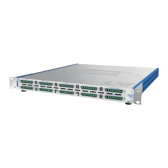
- Page 1 60-600 User Manual LXI 10 Amp 1-Pole Matrix pickeringtest.com Issue 4.4 November 2020...
- Page 2 © COPYRIGHT (2020) PICKERING INTERFACES. ALL RIGHTS RESERVED. No part of this publication may be reproduced, transmitted, transcribed, translated or stored in any form, or by any means without the written permission of Pickering Interfaces. Technical details contained within this publication are subject to change without notice.
- Page 3 Pickering Interfaces strives to fulfil all relevant environmental laws and regulations and reduce wastes and releases to the environment. Pickering Interfaces aims to design and operate products in a way that protects the environment and the health and safety of its employees, customers and the public. Pickering Interfaces endeavours to develop and manufacture products that can be produced, distributed, used and recycled, or disposed of, in a safe and environmentally friendly manner.
-
Page 4: Product Safety
If this product is heavy reference should be made to the safety instructions for provisions of lifting and moving. STATIC SENSITIVE To indicate that static sensitive devices are present and handling precautions should be followed. REED RELAY MODULE 40-110/115/120/125 LXI 10 AMP 1-POLE POWER MATRIX 60-600 Page (IV) Page (IV) -
Page 5: Table Of Contents
LXI Status Indicators ............6.1 LAN Reset .................6.2 Section 7 Maintenance Information ............7.1 Relay Look-Up Tables ............7.1 60-600 Parts List ............7.13 General Maintenance .............7.16 Relay Replacement ............7.19 Appendix A Fitting Rack Mounting Flanges ..........A.1 LXI 10 AMP 1-POLE POWER MATRIX 60-600 Page (V) - Page 6 THIS PAGE INTENTIONALLY BLANK LXI 10 AMP 1-POLE POWER MATRIX 60-600 Page (VI)
-
Page 7: Warnings And Cautions
I/O signals that may be present. Blanking panels are available to order from Pickering. If the product is not used in this manner for example by using an extender card then additional care must be taken to avoid contact with exposed signals. - Page 8 AND USERS SHOULD CONNECT TO THE FRONT PANEL CONNECTORS WITH CONNECTORS OR CABLE ASSEMBLIES THAT ENSURE OPERATORS WILL NOT INADVERTENTLY COME IN CONTACT WITH HIGH VOLTAGES. LXI HIGH VOLTAGE 2-POLE MATRIX 60-310 Page viii LXI 10 AMP 1-POLE POWER MATRIX 60-600 Page (VIII)
-
Page 9: Technical Specification
• Hot Switch to 125VDC/250VAC, Cold Switch to • 3 Year Warranty 400VDC/250VAC The 60-600 is a high power single pole matrix suitable for power signal routing in large ATE systems. It is available with a selection of X and Y sizes as well as partially populated configurations. - Page 10 SECTION 1 - TECHNICAL SPECIFICATION pickering Overview LXI 10 Amp 1-Pole Matrix – 60-600 60-600-002 10 Amp 32x8 1-Pole Matrix Y1.1 Y1.2 Y1.3 Y1.4 Y1.5 Y1.6 Y1.7 Y1.8 60-600-006 10 Amp Single 16x8 1-Pole Matrix Y2.1 Y2.2 Y2.3 Y2.4 Y2.5 Y2.6...
- Page 11 LXI 10 Amp 1-Pole Matrix – 60-600 Power Relay Type LAN Interface Compliant to LXI Standard 1.4, the 60-600 has a 1000Base-T The 60-600 is constructed with high quality electro-mechanical Ethernet Interface via a standard RJ-45 connector mounted on the power relays.
- Page 12 Product Customization Mating Connectors & Cabling Pickering LXI units are designed and manufactured on our own For connection accessories for the 60-600 please refer to the flexible manufacturing lines, giving complete product control and 90-012D 8-pin Power D-type Connector Accessories data sheet enabling simple customization to meet very specific requirements.
- Page 13 We provide a full range of supporting cable and connector solutions for all our switching products—20 connector families with 1200+ products. We offer everything from simple mating connectors to complex cables assemblies and terminal blocks. All assemblies are manufactured by Pickering and are guaranteed to mechanically and electrically mate to our modules. Connectors & Backshells...
- Page 14 Signal Routing Software Our signal routing software, Switch Path Manager, automatically selects and energizes switch paths through Pickering switching systems. Signal routing is performed by simply defining test system endpoints to be connected together, greatly accelerating Test System software development.
-
Page 15: Functional Description
SECTION 2 - TECHNICAL DESCRIPTION FUNCTIONAL DESCRIPTION The 60-600 is a 1-pole 10 Amp matrix available in 16x16, 16x8, 16x4, 32x8, 32x4, 64x4, dual 16x8 or dual 32x4 formats as well as custom configurations. The chassis contains an embedded processor assembly, power supply and between one and four matrix cards. -
Page 16: Maximum Frequency Of Operations At Full Load
0.3Hz to avoid the resulting heat damaging the relay plastic components. Repeated operation at closer time intervals under full load will result in premature relay failure. LXI 10 AMP 1-POLE POWER MATRIX 60-600 Page 2.2... -
Page 17: Installation
INSTALLING THE POWER MATRIX The 60-600 may be mounted on a desk top or fitted into a standard 19 inch rack (rack mounting flanges are supplied with the unit and can be fitted to either side of the front panel). When fitting into a rack it is important to provide adequate support using side brackets or runners, the mounting holes in the front panel flanges are designed only for securing the unit in the rack and must NOT be used to support the weight of the whole unit. -
Page 18: Setting The Ip Address
SETTING THE IP ADDRESS To use the 60-600 LXI Power Matrix over a LAN connection it should be set up and configured as described in the “LXI Getting Started Guide” document. If the IP address is to be set manually and before connecting to a network, contact your IT department so they can give you the correct settings for: •... -
Page 19: Installing The Software
SOFT FRONT PANEL OPERATION The 60-600 LXI Power Matrix can be programmed using the Soft Front Panel. This can be run as a Java Applet from the device’s LXI home page. You must have the Java Runtime environment loaded from Sun Microsystems to use this facility. - Page 20 SECTION 3 - INSTALLATION pickering THIS PAGE INTENTIONALLY BLANK LXI 10 AMP 1-POLE POWER MATRIX 60-600 Page 3.4...
-
Page 21: Programming Guide
SECTION 4 - PROGRAMMING GUIDE PROGRAMMING OPTIONS FOR PICKERING INTERFACES LXI UNITS For information on the installation and use of drivers and the programming of Pickering’s products in various software environments, please refer to the Software User Manual. This is available as a download from: https://www.pickeringtest.com/support/software-drivers-and-downloads... -
Page 22: Programming The 60-600
PROGRAMMING THE 60-600 The 60-600 is a switching matrix which is available in a number of different sizes, for example, the 60-600-001 variant has 16 connections on its X axis and 16 on its Y axis as shown below:. - Page 23 The Direct I/O driver is in reality composed of a suite of separate libraries which interact to provide full control of a Pickering LXI unit. In the case of a switch card the communications library picmlx, and the switching library piplx, are needed.
- Page 24 The following code snippet demonstrates the minimum steps required to operate a switch on a Pickering LXI unit. Firstly a device session is opened on the card located at bus 0, device 20 inside the LXI unit located at 192.168.1.100.
- Page 25 Soft Front Panel The 60-600 Power Matrix can be programmed using the supplied Soft Front Panel. This can be run as a Java Applet from the devices LXI home page. An example of this is shown in Figure 4.2. For a description of the controls, refer to “Soft Front Panel Operation”...
-
Page 26: Command Line Control
LXI instrument from the Windows utility PILMon and provides identical functionality. Enabling the Command Line Control Utility Pickering LXI devices do not provide an SSH server in the normal configuration state, the service must be explicitly enabled. - Page 27 SECTION 4 - PROGRAMMING GUIDE pickering Step 2 - Enable the SSH server Select the Diagnostics page from the main menu LXI 10 AMP 1-POLE POWER MATRIX 60-600 Page 4.7...
- Page 28 LAN Reset button located at the rear of the device in the appropriate manner, refer to Section 7 of this manual for details of this process. Disabling security will stop the SSH service. LXI 10 AMP 1-POLE POWER MATRIX 60-600 Page 4.8...
- Page 29 First start up the SSH client and enter the IP address of the LXI device. The user will be prompted for a login name and password. The username for instrument control is ‘sshuser’, the password is that defined by the user when setting security. LXI 10 AMP 1-POLE POWER MATRIX 60-600 Page 4.9...
- Page 30 Before attempting to control a card it is important to understand the switch architecture of that card and to know how to address the required switch. Each Pickering switch card is represented as a set of one or more sub-units, each sub-unit containing one or more switches.
- Page 31 In the case of matrix sub-units, the XC and XO commands are useful, obviating the need for the user to calculate the bit position for a crosspoint in the matrix by allowing a point to be addressed by row and column address. LXI 10 AMP 1-POLE POWER MATRIX 60-600 Page 4.11...
- Page 32 = UNMASK|MASK an individual output MB <bit_pattern> = set OUTPUT sub-unit mask (to hex bit-pattern) = view sub-unit output mask (as hex bit-pattern) = take control of all Pickering switch cards = release control of all Pickering switch cards VO <bus> <slot> = open card at specified location VC <card>...
-
Page 33: Using The Soft Front Panel
SECTION 4 - PROGRAMMING GUIDE pickering USING THE SOFT FRONT PANEL LXI 10 AMP 1-POLE POWER MATRIX 60-600 Page 4.13... - Page 34 SECTION 4 - PROGRAMMING GUIDE pickering THIS PAGE INTENTIONALLY BLANK LXI 10 AMP 1-POLE POWER MATRIX 60-600 Page 4.14...
-
Page 35: Connections
SECTION 5 - CONNECTOR INFORMATION pickering SECTION 5 - CONNECTIONS Figure 5.1 - Pinout: 60-600-001 Single 16x16 Matrix Figure 5.2 - Pinout: 60-600-002 Single 32x8 Matrix LXI 10 AMP 1-POLE POWER MATRIX 60-600 Page 5.1... - Page 36 Xb16 Xb15 Xb14 Xb13 Xb12 Xb11 Xb10 Xa16 Xa15 Xa14 Xa13 Xa12 Xa11 Xa10 Figure 5.4 - Pinout: 60-600-004 Dual 16x8 Matrix Figure 5.3 - Pinout: 60-600-003 Single 64x4 Matrix LXI 10 AMP 1-POLE POWER MATRIX 60-600 Page 5.2...
- Page 37 Xa28 Xa20 Xa27 Xa19 Xa26 Xa18 Xa25 Xa17 Xa16 Xa15 Xa14 Xa13 Xa12 Xa11 Xa10 Figure 5.6 - Pinout: 60-600-006 Single 16x8 Matrix Figure 5.5 - Pinout: 60-600-005 Dual 32x4 Matrix LXI 10 AMP 1-POLE POWER MATRIX 60-600 Page 5.3...
- Page 38 SECTION 5 - CONNECTOR INFORMATION pickering Figure 5.8 - Pinout: 60-600-008 Single 16x4 Matrix Figure 5.7 - Pinout: 60-600-007 Single 32x4 Matrix LXI 10 AMP 1-POLE POWER MATRIX 60-600 Page 5.4...
- Page 39 X17B X16B X16A X15B X15A X14B X14A X13A X13B X12B X12A X11A X11B X20A X10B Figure 5.9 - Pinout: 60-600-901 Single 16x10 Matrix Figure 5.10 - Pinout: 60-600-902 Dual 32x1 Matrix LXI 10 AMP 1-POLE POWER MATRIX 60-600 Page 5.5...
- Page 40 SECTION 5 - CONNECTOR INFORMATION pickering Ethernet Port Reset Button Service Port (for Pickering diagnostics only) IP Address Display Mains Inlet Fuses Power Switch Figure 5.11 - 60-600 Power Matrix Rear Panel LXI 10 AMP 1-POLE POWER MATRIX 60-600 Page 5.6...
-
Page 41: Trouble Shooting
Refer to the Warnings and Cautions at the front of this manual INSTALLATION PROBLEMS The Plug & Play functionality of Pickering switching products generally ensures trouble-free installation. If you do experience any installation problems you should first ensure that all cables are properly connected. -
Page 42: Lan Reset
Q All of my device’s lights are on, why don’t I see a green Ready light, even after a few minutes? Your device has a fault, contact your local sales office. Please contact your local Pickering Interfaces sales office for any further support or email: Lxisupport@pickeringtest.com You can also visit our website for product updates, help and downloadable materials at: http://www.pickeringtest.com... -
Page 43: Maintenance Information
Please refer to the end of this section for a description on how to remove a matrix daughter board and replace a faulty relay. LXI HIGH DENSITY EMR MATRIX 60-550/551 LXI 10 AMP 1-POLE POWER MATRIX 60-600 Page 7.1 Page 7.1... - Page 44 SECTION 7 - MAINTENANCE INFORMATION pickering Table 7-1. Relay Look-Up Table - Single 16 x 16 Matrix (60-600-001) Left End Daughter Board Left Centre Daughter Board Right Centre Daughter Board Right End Daughter Board Crosspoint Crosspoint Crosspoint Crosspoint Relay Relay...
- Page 45 SECTION 7 - MAINTENANCE INFORMATION pickering Table 7-2. Relay Look-Up Table - Single 32 x 8 Matrix (60-600-002) Left End Daughter Board Left Centre Daughter Board Right Centre Daughter Board Right End Daughter Board Crosspoint Crosspoint Crosspoint Crosspoint Relay Relay...
- Page 46 SECTION 7 - MAINTENANCE INFORMATION pickering Table 7-3. Relay Look-Up Table - Single 64 x 4 Matrix (60-600-003) Left End Daughter Board Left Centre Daughter Board Right Centre Daughter Board Right End Daughter Board Crosspoint Crosspoint Crosspoint Crosspoint Relay Relay...
- Page 47 SECTION 7 - MAINTENANCE INFORMATION pickering Table 7-4. Relay Look-Up Table - Dual 16 x 8 Matrix (60-600-004) Left End Daughter Board Left Centre Daughter Board Right Centre Daughter Board Right End Daughter Board Crosspoint Crosspoint Crosspoint Crosspoint Relay Relay...
- Page 48 SECTION 7 - MAINTENANCE INFORMATION pickering Table 7-5. Relay Look-Up Table - Dual 32 x 4 Matrix (60-600-005) Left End Daughter Board Left Centre Daughter Board Right Centre Daughter Board Right End Daughter Board Crosspoint Crosspoint Crosspoint Crosspoint Relay Relay...
- Page 49 SECTION 7 - MAINTENANCE INFORMATION pickering Table 7-6. Relay Look-Up Table - Single 16 x 8 Matrix (60-600-006) Left End Daughter Board Left Centre Daughter Board Right Centre Daughter Board Right End Daughter Board Crosspoint Crosspoint Crosspoint Crosspoint Relay Relay...
- Page 50 SECTION 7 - MAINTENANCE INFORMATION pickering Table 7-7. Relay Look-Up Table - Single 32 x 4 Matrix (60-600-007) Left End Daughter Board Left Centre Daughter Board Right Centre Daughter Board Right End Daughter Board Crosspoint Crosspoint Crosspoint Crosspoint Relay Relay...
- Page 51 SECTION 7 - MAINTENANCE INFORMATION pickering Table 7-8. Relay Look-Up Table - Single 16 x 4 Matrix (60-600-008) Left End Daughter Board Left Centre Daughter Board Right Centre Daughter Board Right End Daughter Board Crosspoint Crosspoint Crosspoint Crosspoint Relay Relay...
- Page 52 SECTION 7 - MAINTENANCE INFORMATION pickering Table 7-9. Relay Look-Up Table - Single 16 x 10 Matrix (60-600-901) Left End Daughter Board Left Centre Daughter Board Right Centre Daughter Board Right End Daughter Board Crosspoint Crosspoint Crosspoint Crosspoint Relay Relay...
- Page 53 SECTION 7 - MAINTENANCE INFORMATION pickering Table 7-10. Relay Look-Up Table - Dual 32 x 1 Matrix (60-600-902) Left End Daughter Board Left Centre Daughter Board Right Centre Daughter Board Right End Daughter Board Crosspoint Crosspoint Crosspoint Crosspoint Relay Relay...
- Page 54 RL23 RL39 RL55 RL22 RL38 RL54 RL21 RL37 RL53 RL20 RL36 RL52 RL19 RL35 RL51 RL18 RL34 RL50 RL17 RL33 RL49 Figure 7-1. Relay Locations - 60-600 Power Matrix Daughter Board LXI 10 AMP 1-POLE POWER MATRIX 60-600 Page 7.12...
- Page 55 60-600 CHASSIS PARTS LIST Depending upon the specific variant, the 60-600 LXI 10 Amp Matrix chassis contains one, two, three or four matrix daughter boards mounted on a carrier board. As well as the matrix boards, the chassis houses a Power Supply, Distribution Board and a Microcontroller assembly.
- Page 56 Microcontroller Board † Note: the fan assembly consists of 4 fans and the Fan Control Board. The board is listed separately as it is available on it own as a service part. LXI 10 AMP 1-POLE POWER MATRIX 60-600 Page 7.14...
- Page 57 DISTRIBUTION BOARD MICROCONTROLLER 16x4 MATRIX DAUGHTER BOARD 16x4 MATRIX DAUGHTER BOARD POWER SUPPLY 16x4 MATRIX DAUGHTER BOARD CARRIER BOARD SPARE RELAY BOARD Figure 7-3. 60-600 LXI 10 Amp Matrix: Chassis Layout LXI 10 AMP 1-POLE POWER MATRIX 60-600 Page 7.15...
-
Page 58: General Maintenance
Switch Drivers and Relay Matrix The signal switching for the 60-600 is carried out by matrix daughter boards mounted on a carrier board assembly. The signal connectors mounted on the front panel of the unit are hard wired to the matrix switching boards with high current cabling. - Page 59 The Fan Controller Board is fed with 12 volts via the DC Distribution Board and provides a regulated supply for the fans with a preset speed control. LXI 10 AMP 1-POLE POWER MATRIX 60-600 Page 7.17...
- Page 60 Cooling Fan Assembly (A/MS/631) Power Connector and Cooling Fan Switch (C/CN/1195) With Fuse Drawer (C/CN/1196) 60-600 CHASSIS Mains Power Input Figure 7-4. Internal Wiring For the 60-600 LXI 10 Amp Matrix LXI 10 AMP 1-POLE POWER MATRIX 60-600 Page 7.18...
-
Page 61: Relay Replacement
PCB. The positions of the ribbon cable connectors are shown below, in this example there are three, a fully populated chassis will have four. LXI 10 AMP 1-POLE POWER MATRIX 60-600 Page 7.19... - Page 62 5. Remove the fifteen screws fixing the Carrier Board to the base plate of the chassis as highlighted below. The use of a magnetic tipped screwdriver is recommended to help removal of the screws. LXI 10 AMP 1-POLE POWER MATRIX 60-600 Page 7.20...
- Page 63 13. Re-fit the top cover into the retaining slots in the side extrusions and slide forward until it is fully home against the back edge of the front panel. Then secure with the four fixing screws. 14. Re-attach the cabling, apply power, and the unit is ready for use. LXI 10 AMP 1-POLE POWER MATRIX 60-600 Page 7.21...
- Page 64 SECTION 7 - MAINTENANCE INFORMATION pickering THIS PAGE INTENTIONALLY BLANK LXI 10 AMP 1-POLE POWER MATRIX 60-600 Page 7.22...
-
Page 65: Fitting Rack Mounting Flanges
APPENDIX A - FITTING RACK MOUNTING FLANGES Pickering’s LXI devices are supplied with mounting flanges to enable fitting into a standard 19 inch rack. The following procedure describes the attachment of the flanges to the unit’s side extrusions, a No.1 cross head screwdriver will be required. - Page 66 APPENDIX A - FITTING RACK MOUNTING FLANGES pickering THIS PAGE INTENTIONALLY BLANK LXI 10 AMP 1-POLE POWER MATRIX 60-600 Page A.2...
Need help?
Do you have a question about the 60-600 and is the answer not in the manual?
Questions and answers