
Related Manuals for Pickering 60-310


Summary of Contents for Pickering 60-310
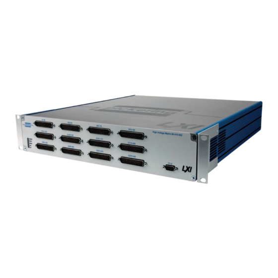
- Page 1 60-310 User Manual LXI High Voltage 2-Pole Matrix pickeringtest.com Issue 4.4 September 2021...
- Page 2 © COPYRIGHT (2021) PICKERING INTERFACES. ALL RIGHTS RESERVED. No part of this publication may be reproduced, transmitted, transcribed, translated or stored in any form, or by any means without the written permission of Pickering Interfaces. Technical details contained within this publication are subject to change without notice.
- Page 3 Pickering Interfaces strives to fulfil all relevant environmental laws and regulations and reduce wastes and releases to the environment. Pickering Interfaces aims to design and operate products in a way that protects the environment and the health and safety of its employees, customers and the public. Pickering Interfaces endeavours to develop and manufacture products that can be produced, distributed, used and recycled, or disposed of, in a safe and environmentally friendly manner.
-
Page 4: Product Safety
If this product is heavy reference should be made to the safety instructions for provisions of lifting and moving. STATIC SENSITIVE To indicate that static sensitive devices are present and handling precautions should be followed. REED RELAY MODULE 40-110/115/120/125 LXI HIGH VOLTAGE 2-POLE MATRIX 60-310 Page iv Page (IV) -
Page 5: Table Of Contents
LAN Reset ..............6.2 Section 7 Maintenance Information ...........7.1 Relay Location Data ..........7.1 High Voltage Matrix Parts List ........7.6 General Maintenance ..........7.9 Matrix PCB Removal & Refitting ......7.12 Appendix A Fitting Rack Mounting Flanges ........A.1 LXI HIGH VOLTAGE 2-POLE MATRIX 60-310 Page v... - Page 6 THIS PAGE INTENTIONALLY BLANK LXI HIGH VOLTAGE 2-POLE MATRIX 60-310 Page vi...
-
Page 7: Warnings And Cautions
I/O signals that may be present. Blanking panels are available to order from Pickering. If the product is not used in this manner for example by using an extender card then additional care must be taken to avoid contact with exposed signals. - Page 8 TO PREVENT ACCIDENTAL CONTACT WHILE IN USE. SYSTEM INTEGRATORS AND USERS SHOULD CONNECT TO THE FRONT PANEL CONNECTORS WITH CONNECTORS OR CABLE ASSEMBLIES THAT ENSURE OPERATORS WILL NOT INADVERTENTLY COME IN CONTACT WITH HIGH VOLTAGES. LXI HIGH VOLTAGE 2-POLE MATRIX 60-310 Page viii...
-
Page 9: Technical Specification
SECTION 1 - TECHNICAL SPECIFICATION • 2-Pole 300x2 Matrix The 60-310 is a 2-pole Matrix Module available in 300x2, 200x2 and 100x2 formats. It is capable of cold switching 1000VDC and has a • Cold Switch up to 750VDC Working / maximum carry current of 1A. - Page 10 LXI High Voltage Matrix – 60-310 Relay Type LAN Interface The 60-310 is fitted with high quality rhodium contact reed relays Compliant to LXI Standard 1.4, the 60-310 has a 1000Base-T specifically designed for high voltage switching. These relays are...
- Page 11 Customization can include: Mating Connectors & Cabling • Alternative reed relay types For connection accessories for the 60-310 please refer to the • Mixture of reed relay types 90-005HVD High Voltage 50-pin D-type and 90-003HVD High •...
- Page 12 We provide a full range of supporting cable and connector solutions for all our switching products—20 connector families with 1200+ products. We offer everything from simple mating connectors to complex cables assemblies and terminal blocks. All assemblies are manufactured by Pickering and are guaranteed to mechanically and electrically mate to our modules. Connectors & Backshells...
- Page 13 Signal Routing Software Our signal routing software, Switch Path Manager, automatically selects and energizes switch paths through Pickering switching systems. Signal routing is performed by simply defining test system endpoints to be connected together, greatly accelerating Test System software development.
- Page 14 SECTION 1 - TECHNICAL SPECIFICATION pickering THIS PAGE INTENTIONALLY BLANK Page 1.6 LXI HIGH VOLTAGE 2-POLE MATRIX 60-310...
- Page 15 SECTION 2 - TECHNICAL DESCRIPTION FUNCTIONAL DESCRIPTION The 60-310 is a 2-pole high voltage matrix available in 100x2, 200x2 or 300x2 formats. The chassis contains an embedded processor assembly, bridge card, power supplies and one, two or three matrix cards. Each matrix card contains the relays and driver circuit for a 2-pole 100x2 matrix as well as the connectors for the X-bus, the lower card also contains the connector for the Y-bus.
- Page 16 SECTION 2 - TECHNICAL DESCRIPTION pickering THIS PAGE INTENTIONALLY BLANK Page 2.2 LXI HIGH VOLTAGE 2-POLE MATRIX 60-310...
- Page 17 INSTALLING THE HIGH VOLTAGE MATRIX The 60-310 may be mounted on a desk top or fitted into a standard 19 inch rack (rack versions are supplied with mounting flanges fitted to either side of the front panel). When fitting into a rack it is important to provide adequate support using side brackets or runners, the mounting holes in the front panel flanges are designed only for securing the unit in the rack and must NOT be used to support the weight of the whole unit.
-
Page 18: Installation
Figure 3-2. Side view of the High Voltage Matrix showing the left hand side intake for cooling air SETTING THE IP ADDRESS To use the 60-310 High Voltage Matrix over a LAN connection it should be set up and configured as described in the “LXI Getting Started Guide” documentl. -
Page 19: Soft Front Panel Operation
SOFT FRONT PANEL OPERATION The 60-310 High Voltage Matrix can be programmed using the Soft Front Panel. This can be run as a Java Applet from the device’s home page. You must have the Java Runtime environment loaded from Sun Microsystems to use this facility. - Page 20 SECTION 3 - INSTALLATION pickering THIS PAGE INTENTIONALLY BLANK Page 3.4 LXI HIGH VOLTAGE 2-POLE MATRIX 60-310...
-
Page 21: Programming Guide
SECTION 4 - PROGRAMMING GUIDE PROGRAMMING OPTIONS FOR PICKERING INTERFACES LXI UNITS For information on the installation and use of drivers and the programming of Pickering’s products in various software environments, please refer to the Software User Manual. This is available as a download from: https://www.pickeringtest.com/support/software-drivers-and-downloads... -
Page 22: Programming The 60-310
PROGRAMMING THE 60-310 The 60-310 is a matrix card which in its fully populated form has 300 connections on its X axis and 2 on its Y axis. All crosspoints are 2-pole, therefore all paths through the matrix are 2-wire. Smaller versions are also available. - Page 23 The Direct I/O driver is in reality composed of a suite of separate libraries which interact to provide full control of a Pickering LXI unit. In the case of a switch card the communications library picmlx, and the switching library piplx, are needed.
- Page 24 The following code snippet demonstrates the minimum steps required to operate a switch on a Pickering LXI unit. Firstly a device session is opened on the card located at bus 0, device 20 inside the LXI unit located at 192.168.1.100.
- Page 25 Soft Front Panel The 60-310 High Voltage Matrix can be programmed using the supplied Soft Front Panel. This can be run as a Java Applet from the devices home page. An example of this is shown in Figure 4.2. For a description of the controls, refer to “Soft Front Panel Operation”...
-
Page 26: Command Line Control
COMMAND LINE CONTROL OF PICKERING INSTRUMENTS Overview Command line control of the Pickering device range was added in firmware release 2.11. The utility provided was ported to the instrument from the Windows utility PILMon and provides identical functionality. Enabling the Command Line Control Utility Pickering devices do not provide an SSH server in the normal configuration state, the service must be explicitly enabled. - Page 27 SECTION 4 - PROGRAMMING GUIDE pickering Step 2 - Enable the SSH server Select the Diagnostics page from the main menu LXI HIGH VOLTAGE 2-POLE MATRIX 60-310 Page 4.7...
- Page 28 LAN Reset button located at the rear of the device in the appropriate manner, refer to Section 7 of this manual for details of this process. Disabling security will stop the SSH service. LXI HIGH VOLTAGE 2-POLE MATRIX 60-310 Page 4.8...
- Page 29 First start up the SSH client and enter the IP address of the device. The user will be prompted for a login name and password. The username for instrument control is ‘sshuser’, the password is that defined by the user when setting security. LXI HIGH VOLTAGE 2-POLE MATRIX 60-310 Page 4.9...
- Page 30 Before attempting to control a card it is important to understand the switch architecture of that card and to know how to address the required switch. Each Pickering switch card is represented as a set of one or more sub-units, each sub-unit containing one or more switches.
- Page 31 In the case of matrix sub-units, the XC and XO commands are useful, obviating the need for the user to calculate the bit position for a crosspoint in the matrix by allowing a point to be addressed by row and column address. LXI HIGH VOLTAGE 2-POLE MATRIX 60-310 Page 4.11...
- Page 32 = UNMASK|MASK an individual output MB <bit_pattern> = set OUTPUT sub-unit mask (to hex bit-pattern) = view sub-unit output mask (as hex bit-pattern) = take control of all Pickering switch cards = release control of all Pickering switch cards VO <bus> <slot> = open card at specified location VC <card>...
-
Page 33: Using The Soft Front Panel
SECTION 4 - PROGRAMMING GUIDE pickering USING THE SOFT FRONT PANEL LXI HIGH VOLTAGE 2-POLE MATRIX 60-310 Page 4.13... - Page 34 SECTION 4 - PROGRAMMING GUIDE pickering THIS PAGE INTENTIONALLY BLANK LXI HIGH VOLTAGE 2-POLE MATRIX 60-310 Page 4.14...
-
Page 35: Connections
SECTION 5 - CONNECTIONS Figure 5-2. Figure 5-1. Front Panel Connector Layout for the Front Panel Connector Layout for the 60-310-202 LXI 2-Pole 200x2 High Voltage Matrix 60-310-102 LXI 2-Pole 100x2 High Voltage Matrix Page 5.1 LXI HIGH VOLTAGE 2-POLE MATRIX 60-310... - Page 36 Power Switch Fuses Mains Inlet Figure 5-4. Rear Panel Connector Layout for Figure 5-3. Front Panel Connector Layout for the 60-310-302 LXI 2-Pole 300x2 High Voltage Matrix the 60-310 High Voltage 2-Pole Matrix Page 5.2 LXI HIGH VOLTAGE 2-POLE MATRIX 60-310...
- Page 37 X39.2 X40.2 X41.1 X42.1 X43.1 X41.2 X42.2 X43.2 X44.1 X45.1 X46.1 X44.2 X45.2 X46.2 X47.1 X48.1 X49.1 X47.2 X48.2 X49.2 X50.1 X50.2 Figure 5.5 - 60-310-102/202/302 “X1-X25” and “X26 to X50” Connectors Page 5.3 LXI HIGH VOLTAGE 2-POLE MATRIX 60-310...
- Page 38 X89.2 X90.2 X91.1 X92.1 X93.1 X91.2 X92.2 X93.2 X94.1 X95.1 X96.1 X94.2 X95.2 X96.2 X97.1 X98.1 X99.1 X97.2 X98.2 X99.2 X100.1 X100.2 Figure 5.6 - 60-310-102/202/302 “X51-X75” and “X76 to X100” Connectors Page 5.4 LXI HIGH VOLTAGE 2-POLE MATRIX 60-310...
- Page 39 X139.2 X140.2 X141.1 X142.1 X143.1 X141.2 X142.2 X143.2 X144.1 X145.1 X146.1 X144.2 X145.2 X146.2 X147.1 X148.1 X149.1 X147.2 X148.2 X149.2 X150.1 X150.2 Figure 5.7 - 60-310-202/302 “X101-X125” and “X126 to X150” Connectors Page 5.5 LXI HIGH VOLTAGE 2-POLE MATRIX 60-310...
- Page 40 X189.2 X190.2 X191.1 X192.1 X193.1 X191.2 X192.2 X193.2 X194.1 X195.1 X196.1 X194.2 X195.2 X196.2 X197.1 X198.1 X199.1 X197.2 X198.2 X199.2 X200.1 X200.2 Figure 5.8 - 60-310-202/302 “X151-X175” and “X176 to X200” Connectors Page 5.6 LXI HIGH VOLTAGE 2-POLE MATRIX 60-310...
- Page 41 X239.2 X240.2 X241.1 X242.1 X243.1 X241.2 X242.2 X243.2 X244.1 X245.1 X246.1 X244.2 X245.2 X246.2 X247.1 X248.1 X249.1 X247.2 X248.2 X249.2 X250.1 X250.2 Figure 5.9 - 60-310-302 “X201-X225” and “X226 to X250” Connectors Page 5.7 LXI HIGH VOLTAGE 2-POLE MATRIX 60-310...
- Page 42 X289.2 X290.2 X291.1 X292.1 X293.1 X291.2 X292.2 X293.2 X294.1 X295.1 X296.1 X294.2 X295.2 X296.2 X297.1 X298.1 X299.1 X297.2 X298.2 X299.2 X300.1 X300.2 Figure 5.10 - 60-310-302 “X251-X275” and “X276 to X300” Connectors Page 5.8 LXI HIGH VOLTAGE 2-POLE MATRIX 60-310...
- Page 43 SECTION 5 - CONNECTOR INFORMATION pickering Y1-2 9-pin D-Type Plug - “Y1-2” Pin No. Signal Name Pin No. Signal Name Y1.1 Y1.2 Y2.1 Y2.2 FP_GND Figure 5.11 - 60-310-102/202/302 “Y1-2” Connector Page 5.9 LXI HIGH VOLTAGE 2-POLE MATRIX 60-310...
- Page 44 SECTION 5 - CONNECTOR INFORMATION pickering Page 5.10 LXI HIGH VOLTAGE 2-POLE MATRIX 60-310...
-
Page 45: Troubleshooting
Refer to the Warnings and Cautions at the front of this manual INSTALLATION PROBLEMS The Plug & Play functionality of Pickering switching products generally ensures trouble-free installation. If you do experience any installation problems you should first ensure that all cables are properly connected. -
Page 46: Lan Reset
Q All of my device’s lights are on, why don’t I see a green Ready light, even after a few minutes? Your device has a fault, contact your local sales office. Please contact your local Pickering Interfaces sales office for any further support or email: support@pickeringtest.com You can also visit our website for product updates, help and downloadable materials at: http://www.pickeringtest.com... -
Page 47: Maintenance Information
Tables 7-2, 7-3 and 7-4 on the following pages provide a cross reference between the relay number and the cross- points on the matrix boards fitted in the 60-310 chassis. This can be used in conjunction with the PCB layout diagram RELAY LOOK-UP TABLES in Figure 7-1 to help to locate the position of faulty relays, this diagram also shows the location of the spare relay. - Page 48 RL255 RL295 RL136 RL176 RL216 RL256 RL296 RL137 RL177 RL217 RL257 RL297 RL138 RL178 RL218 RL258 RL298 RL139 RL179 RL219 RL259 RL299 RL140 RL180 RL220 RL260 RL300 NOTE: All Crosspoints are 2-Pole Page 7.2 LXI HIGH VOLTAGE 2-POLE MATRIX 60-310...
- Page 49 RL255 RL295 RL136 RL176 RL216 RL256 RL296 RL137 RL177 RL217 RL257 RL297 RL138 RL178 RL218 RL258 RL298 RL139 RL179 RL219 RL259 RL299 RL140 RL180 RL220 RL260 RL300 NOTE: All Crosspoints are 2-Pole Page 7.3 LXI HIGH VOLTAGE 2-POLE MATRIX 60-310...
- Page 50 RL255 RL295 RL136 RL176 RL216 RL256 RL296 RL137 RL177 RL217 RL257 RL297 RL138 RL178 RL218 RL258 RL298 RL139 RL179 RL219 RL259 RL299 RL140 RL180 RL220 RL260 RL300 NOTE: All Crosspoints are 2-Pole Page 7.4 LXI HIGH VOLTAGE 2-POLE MATRIX 60-310...
- Page 51 RL289 RL239 RL281 RL231 RL297 RL248 RL290 RL240 RL282 RL232 RL299 RL249 RL291 RL241 RL283 RL233 Figure 7-1. PCB layout for one 100x2 2-Pole High Voltage Matrix Board with relay positions highlighted Page 7.5 LXI HIGH VOLTAGE 2-POLE MATRIX 60-310...
-
Page 52: High Voltage Matrix Parts List
HIGH VOLTAGE MATRIX PARTS LISTS The 60-310 LXI High Voltage Matrix chassis contains up to three 100x2 2-pole Matrix Boards as well as Power Supplies and a Microcontroller assembly. The following pages provide a parts list and internal layout for the PCBs and sub-assemblies that make up the 300x2 High Voltage Matrix. - Page 53 Ribbon Cable: Matrix Board #2 to Matrix 36-pin C-CN-924 Board #3 Ribbon Cable: Microcontroller Board to LXI 16-pin C-CN-951 Status LED Board Ribbon Cable: FPGA Bridge Daughter 40-pin C-CN-979 Board to Matrix Board #1 Page 7.7 LXI HIGH VOLTAGE 2-POLE MATRIX 60-310...
- Page 54 HIGH VOLTAGE MATRIX BOARD #1 - 100x2 2-POLE HIGH VOLTAGE MATRIX BOARD #2 - 100x2 2-POLE HIGH VOLTAGE MATRIX BOARD #3 - 100x2 2-POLE Figure 7-3. 60-310 LXI High Voltage Matrix: Chassis Layout (fully populated 300x2 2-pole matrix) Page 7.8 LXI HIGH VOLTAGE 2-POLE MATRIX 60-310...
-
Page 55: General Maintenance
Switch Drivers and Relay Matrix The signal switching for the 60-310 is carried out by up to three High Voltage Matrix Boards. X and Y signals to the matrix are via front panel mounted D-type plugs which are connected to the matrix boards via wiring harnesses. - Page 56 The fans are driven with 12V from PSU2 via DC distribution board D. Page 7.10 LXI HIGH VOLTAGE 2-POLE MATRIX 60-310...
- Page 57 Power Connector and Switch (C/CN/1195) Cooling Fan With Fuse Drawer Assembly (C/CN/1196) (A/MS/630) 60-310 CHASSIS Mains Power Input Figure 7-4. Internal Wiring For the 60-310 LXI High Voltage Matrix (fully populated 300x2 2-Pole) Page 7.11 LXI HIGH VOLTAGE 2-POLE MATRIX 60-310...
-
Page 58: Matrix Pcb Removal & Refitting
MATRIX PCB REMOVAL & REFITTING In case of relay failiure, the matrix cards of the 60-310 may be removed for repair or replacement. The chassis may be fitted with one, two or three indentical matrix PCBs depending upon the overall specified matrix size (100x2, 200x2 or 300x2). - Page 59 7. Lift the board clear of the chassis ready for repair or replacement. 8. To refit the matrix board follow the steps described in reverse order. Figure 7-6. Location of the four screw-lock nuts securing the Matrix PCB to the front panel Page 7.13 LXI HIGH VOLTAGE 2-POLE MATRIX 60-310...
- Page 60 SECTION 7 - MAINTENANCE INFORMATION pickering THIS PAGE INTENTIONALLY BLANK Page 7.14 LXI HIGH VOLTAGE 2-POLE MATRIX 60-310...
-
Page 61: Fitting Rack Mounting Flanges
APPENDIX A - FITTING RACK MOUNTING FLANGES Pickering’s devices are supplied with mounting flanges to enable fitting into a standard 19 inch rack. The following procedure describes the attachment of the flanges to the unit’s side extrusions, a No.1 cross head screwdriver will be required. - Page 62 APPENDIX A - FITTING RACK FLANGES pickering THIS PAGE INTENTIONALLY BLANK Page A.2 LXI HIGH VOLTAGE 2-POLE MATRIX 60-310...
Need help?
Do you have a question about the 60-310 and is the answer not in the manual?
Questions and answers