Table of Contents
Advertisement
Available languages
Available languages
Quick Links
Einbau- und Betriebsanleitung
Installation and Operating Instructions
Instructions de montage et de service
Elektrischer Stellantrieb
Electric Actuator
Servomoteur électrique
Inhalt/ Content/ Index
REact60_100-8010v1.0.docx
Seite/ page
2
2
2
2
2
3
3
3
4
4
5
5
5
5
6
6
6
6
6
7
7
7
8
8
9
9
9
9
10
10
10
10
10
11
11
11
12
12
13
13
13
13
14
16
22
25
- 1 -
REact60/ 100-8010
Baureihe/ Series/ Séries
REact60E, REact100E
REact60DC, REact100DC
03/2023
Advertisement
Table of Contents

Related Manuals for RTK CIRCOR REact60E Series


Summary of Contents for RTK CIRCOR REact60E Series
-
Page 1: Table Of Contents
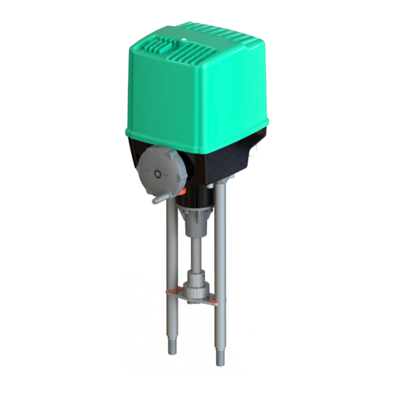
Einbau- und Betriebsanleitung REact60/ 100-8010 Installation and Operating Instructions Instructions de montage et de service Baureihe/ Series/ Séries Elektrischer Stellantrieb REact60E, REact100E Electric Actuator Servomoteur électrique REact60DC, REact100DC Inhalt/ Content/ Index Seite/ page Aufbau auf die Armatur/ Ventil Betriebsbedingungen Gefahrenhinweise Hinweis Entsorgung Elektrischer Anschluss a... -
Page 2: Aufbau Auf Die Armatur/ Ventil
Warnung vor heißen Oberflächen Hinweis Mit den RTK-Stellantrieben werden Regel bzw. Absperrventile betätigt, die einen linearen Nennstellweg erfordern. Einsatzgrenzen sind den technischen Daten zu entnehmen. Der Antrieb darf nur für den vorgesehenen Verwendungszweck eingesetzt werden. Jeder Einsatz des Stellantriebes außerhalb der aufgeführten technischen Daten bzw. unsachgemäßer Gebrauch gilt als nicht bestimmungsgemäß. -
Page 3: Elektrischer Anschluss A
Einbau- und Betriebsanleitung REact60/ 100-8030 Installation and Operating Instructions Instructions de montage et de service Elektrischer Anschluss • Arbeiten an elektrischen Anlagen oder Betriebsmitteln dürfen nur von einer Elektrofachkraft oder von unterwiesenen Personen unter Anleitung und Aufsicht einer Elektrofachkraft den elektrotechnischen Regeln entsprechend vorgenommen werden •... -
Page 4: Einstellungen
Einbau- und Betriebsanleitung REact60/ 100-8040 Installation and Operating Instructions Instructions de montage et de service Einstellungen Einstellung des Hubes Der maximale Hub bei dem REact 60 beträgt 60 mm und bei dem REact 100 80 mm (siehe technische Daten). Der Schlitten, welcher starr verbunden ist, macht bei beiden Antrieben einen Hub von 50 mm. -
Page 5: Einstellung Der Stellgeschwindigkeit Des React 60Dc/ 100Dc
Einbau- und Betriebsanleitung REact60/ 100-8050 Installation and Operating Instructions Instructions de montage et de service Einstellung der Stellgeschwindigkeit des REact 60DC/ 100DC Die Stellgeschwindigkeit kann über einen zwei poligen Schalter (DIP1) eingestellt werden.(Fig.13) Austausch von Komponenten Tausch der Anschlussplatine Achtung Sicherheitsvorschriften beachten Der Stellantrieb muss freigeschaltet sein! •... -
Page 6: Installation Onto Valves
Notice The RTK actuators are used to actuate control or shut-off valves that require a linear nominal travel. Application limits can be found in the data sheets or technical data. The actuator may only be used for the intended purpose. -
Page 7: Electrical Connection A
Einbau- und Betriebsanleitung REact60/ 100-8070 Installation and Operating Instructions Instructions de montage et de service Electrical connection • Work on electrical systems or equipment may only be carried out by a qualified electrician or by trained personal under the guidance and supervision of a qualified electrician in accordance with electrotechnical rules •... -
Page 8: Settings
Einbau- und Betriebsanleitung REact60/ 100-8080 Installation and Operating Instructions Instructions de montage et de service Settings Stroke settings The maximum stroke of the REact 60 amounts to 60 mm and 80 mm for the REact 100 (see technical information. The sliding carriage which is fixed has a stroke of 50 mm for both drives. -
Page 9: Adjustment Of The Positioning Speed (React60Dc/ 100Dc)
Einbau- und Betriebsanleitung REact60/ 100-8090 Installation and Operating Instructions Instructions de montage et de service Adjustment of the positioning speed (REact60DC/ 100DC) The actuating speed can be set using a two-pole switch DIP1(Fig.13). Replacement of components Replacing the terminal board Caution!: Observe the safety regulations The actuator must be disconnected from the power supply.!! -
Page 10: Installation Sur Vannes
Remarque Les actuateurs de RTK sont utilisés pour actionner des vannes de régulation ou d'arrêt nécessitant une course nominale linéaire. Les limites d'application peuvent être trouvées dans les fiches techniques ou les données techniques. L actuateur ne doit être utilisé qu'aux fins prévues. -
Page 11: Connexion Électrique A
Einbau- und Betriebsanleitung REact60/ 100-80110 Installation and Operating Instructions Instructions de montage et de service Connexion électrique • Les travaux sur les systèmes ou équipements électriques ne peuvent être effectués que par un électricien qualifié ou par des personnes formées sous la direction •... -
Page 12: Réglages
Einbau- und Betriebsanleitung REact60/ 100-80120 Installation and Operating Instructions Instructions de montage et de service Réglages Réglage de la course La course maximale est de 60mm pour le REact 60 et de 80mm pour le REact 100 (voir caractéristiques techniques). Le chariot étant relié de manière rigide effectue avec les deux entraînements une course de 50mm. -
Page 13: Réglage De La Vitesse De Positionnement (React60Dc/ 100Dc)
Einbau- und Betriebsanleitung REact60/ 100-80130 Installation and Operating Instructions Instructions de montage et de service Réglage de la vitesse de positionnement (REact60DC/ 100DC) La vitesse de fonctionnement peut être réglée à l'aide d'un interrupteur bipolaire (DIP1).(Fig.13) Remplacement de composants Remplacement du bornier Attention: Respectez les consignes de sécurité... -
Page 14: Technische Daten/ Technical Specifications/ Caractéristiques Techniques
Einbau- und Betriebsanleitung REact60/ 100-80140 Installation and Operating Instructions Instructions de montage et de service Technische Daten/ Technical specifications/ Caractéristiques techniques REact60E/ 100E REact 60E REact 100E Type / type / type -030 -045 -090 -170 -030 -045 -090 Regelkraft / operating force / force de poussé 6,0 kN 10 kN Stellweg / stroke / course... - Page 15 Einbau- und Betriebsanleitung REact60/ 100-80150 Installation and Operating Instructions Instructions de montage et de service REact60DC/ 100DC Type / type / type REact 60DC REact 100DC Regelkraft / operating force / force de poussé 6,0 kN 10 kN Stellweg / stroke / course max.
-
Page 16: Elektrischer Anschluss / Electrical Wiring / Schéma De Câblage
Einbau- und Betriebsanleitung REact60/ 100-80160 Installation and Operating Instructions Instructions de montage et de service Elektrischer Anschluss / Electrical wiring / schéma de câblage siehe separate Verdrahtung und Anschlusspläne, see separate wiring diagrams, voir d'autres plan de câblage für, for, pour le REact60E/ 100E Dokument/ Document No. - Page 17 Einbau- und Betriebsanleitung REact60/ 100-80170 Installation and Operating Instructions Instructions de montage et de service Schlittengruppe/ switch carrier unit/ l’ensemble de caisse E1“ Wegendschalter „Auf“-Richtung, limit switch “open“- direction, interrupteur de fine de course direction “OUVERT“. Wegendschalter „Zu“-Richtung, limit switch “close“- direction, interrupteur de fine de course direction “FERMETURE“.
- Page 18 Einbau- und Betriebsanleitung REact60/ 100-80180 Installation and Operating Instructions Instructions de montage et de service Position- Potentiometer1-2/ Potentiometer / Potentiomètre Fig.5 1 Stellring/ Adjustment ring/ Bague de arrêt 2 Gewindestift/ Threaded pin/ vis sans tete 3 Biegefeder/ Flexible spring/ Ressort de Flexion 4 Linsenschraube/ screw/ vis Fig.4 Heizung...
- Page 19 Einbau- und Betriebsanleitung REact60/ 100-80190 Installation and Operating Instructions Instructions de montage et de service RElog REtrans Fig.8 Fig.9 1 Schrauben selbstschneidend/ self-cutting screws/ Vis auto taraudeuse 1 Befestigungswinkel/ mounting bracket/ équerre de fixation 2 Befestigungswinkel/ mounting bracket/ équerre de fixation 2 Schrauben selbstschneidend/ self-cutting screws/ Vis auto taraudeuse 3 RElog 3 REtrans2W/4W...
- Page 20 Einbau- und Betriebsanleitung REact60/ 100-80200 Installation and Operating Instructions Instructions de montage et de service REact60DC/ 100DC-Motor-Gruppe REdrive Fig. 12 Fig.13 1 2x Linsenschraube / screw / vis M4x10 2 1x REdrive-Platine/ REdrive board/ platine REdrive Dip1 3 2x Abstandsbolzen / distance bolts / boujons d'écartement M4x65 SW7 4 2x Federring / spring washer /...
- Page 21 Einbau- und Betriebsanleitung REact60/ 100-80210 Installation and Operating Instructions Instructions de montage et de service Adaptionsspindel/ adaption spindle/ Broche de adaption Adaptionsspindel/ adaption spindle/ Broche de adaption REact 60_100 mit Säulen / with pillars / avec colonnes Einstellung Hub/ stroke adjustment/ réglage de la course Fig.17 Fig.16...
-
Page 22: Ersatzteilliste / Spare Parts List / Liste De Pièces De Rechange
Einbau- und Betriebsanleitung REact60/ 100-80220 Installation and Operating Instructions Instructions de montage et de service Ersatzteilliste / spare parts list / liste de pièces de rechange REact 60_100 mit Säulen / with pillars / avec colonnes REact60_100-8010v1.0.docx - 22 - 03/2023... - Page 23 Einbau- und Betriebsanleitung REact60/ 100-80230 Installation and Operating Instructions Instructions de montage et de service Adaptionsspindel/ adaption spindle/ Broche de adaption REact60_100-8010v1.0.docx - 23 - 03/2023...
- Page 24 Einbau- und Betriebsanleitung REact60/ 100-80240 Installation and Operating Instructions Instructions de montage et de service Order no. Note CGEHR3000009 Gehäuse-Oberteil Housing – upper part Capot CMUSR3500009 REact 60 Spindelmutter-Gruppe Spindle nut group Ecrou de tige CMUSR4500009 REact 100 CZRAR4000009 Zahnradgruppe 0 Gear group 0 Roue dentée 0 CZRAR3010009...
-
Page 25: Maße/ Dimensions/ La Dimensions
Einbau- und Betriebsanleitung REact60/ 100-80250 Installation and Operating Instructions Instructions de montage et de service Maße/ Dimensions/ La dimensions REact 60E_100E/ REact60DC_100DC mit Säulen / with pillars / avec colonne REact60_100-8010v1.0.docx - 25 - 03/2023... - Page 26 EG-Einbauerklärung 0000-7003 Declaration of Incorporation CE Alle Baureihen/All series/ Toutes les Déclaration d’incorporation CE séries -Orginal- Einbauerklärung gemäß EG- Declaration of Incorporation pursuant to EU – Déclaration d’incorporation suivant la Maschinenrichtlinie 2006/42/EG, Anhang II B Machine guideline 2006/42/EG, appendix II B directive de la CE, relative aux machines 2006/42/CE, annexe II B Wir die Firma:...
- Page 27 CE-Konformitätserklärung 0000-7008 CE-Conformity Declaration Alle Baureihen/All series/ Toutes les séries Déclaration de conformité CE -Orginal- Konformitätserklärung gemäß EG-Richtlinie Conformity declaration pursuant to EU Déclaration de conformité suivant la directive EMV 2014/30/EU und guideline EMV 2014/30/EU and Low-Voltage EMC 2014/30/EU et la directive sur la basse Niederspannungsrichtlinie 2014/35/EU Directive 2014/35/EU tension 2014/35/EU...
Need help?
Do you have a question about the CIRCOR REact60E Series and is the answer not in the manual?
Questions and answers