Table of Contents
Advertisement
Quick Links
Advertisement
Table of Contents

Related Manuals for Cosmo COS-ERC305WKTD


Summary of Contents for Cosmo COS-ERC305WKTD
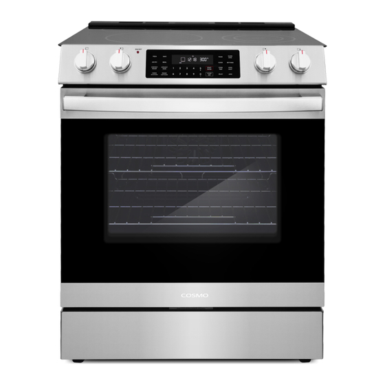
- Page 1 ELECTRIC RANGE COS-ERC305WKTD 30" SLIDE-IN RANGE INSTALLATION INSTRUCTIONS IMPORTANT: READ AND SAVE THESE INSTRUCTIONS. FOR RESIDENTIAL USE ONLY. INSTALLER: PLEASE LEAVE THESE INSTRUCTIONS WITH THIS UNIT FOR THE OWNER. OWNER: PLEASE RETAIN THESE INSTRUCTIONS FOR FUTURE REFERENCE. Rev.23.11...
- Page 2 COSMO Appliances are designed according to the strictest safety and performance standard for the North American market. We follow the most advanced manufacturing philosophy.
-
Page 3: Table Of Contents
TABLE OF CONTENTS RANGE SAFETY....................4 Anti-tip Device ......................5 INSTALLATION REQUIREMENTS ................ 6 Tools and Parts ......................6 Location Requirements .................... 7 Product Specifications ....................8 Product Dimensions ....................9 Clearances ........................ 10 Electrical Requirements ................... 12 INSTALLATION INSTRUCTIONS ................. 15 Remove Old Appliance ................... -
Page 4: Range Safety
RANGE SAFETY READ ALL INSTRUCTIONS BEFORE USING THE APPLIANCE Your safety and the safety of others are very important. We have provided many important safety messages in this manual and on your appliance. Always read and obey all safety messages. This is the safety alert symbol. -
Page 5: Anti-Tip Device
WARNING TIP OVER HAZARD • A child or adult can tip the range and be killed. • Install anti-tip bracket to floor or wall per installation instructions. • Slide range back so rear range foot is engaged in the slot of the anti-tip bracket. -
Page 6: Installation Requirements
INSTALLATION REQUIREMENTS TOOLS AND PARTS Gather the required tools and parts before starting installation. Read and follow the instructions provided with any tools listed here. Tools Needed • Masonry drill bit (for • Tape measure concrete/ceramic floors only) • Phillips screwdriver •... -
Page 7: Location Requirements
LOCATION REQUIREMENTS IMPORTANT: Observe all governing codes and ordinances. Do not obstruct flow of combustion and ventilation air. • It is the installer's responsibility to comply with installation clearances specified on the model/serial/rating plate. The model/serial/rating plate is located inside the storage drawer on either the left or right side panel. Model/Serial/Rating Plate •... -
Page 8: Product Specifications
Four-wire power supply cord or cable must be used in a mobile home installation. The appliance wiring will need to be revised. See "Electrical Connection" section. PRODUCT SPECIFICATIONS Model COS-ERC305WKTD Description 30" Electric Range Oven Capacity 6.3 cu. ft. Electrical Requirements... -
Page 9: Product Dimensions
PRODUCT DIMENSIONS Your model may appear different from the model depicted. Dimensions given are maximum dimensions across all models. COS-ERC305WKTD 31 ¹⁄ " (78.9 cm) With cooktop flanges 35 ¹⁄ " (90.2 cm) Min. height to cooktop flange / cooking surface 26 ³⁄... -
Page 10: Clearances
CLEARANCES IMPORTANT: Some cabinet and building materials are not designed to withstand the heat produced by the oven for baking and self-cleaning. Check with your builder or cabinet supplier to make sure that the materials used will not discolor, delaminate or sustain other damage. GIVEN DIMENSIONS ARE MINIMUM CLEARANCES. - Page 11 Power Supply Location IMPORTANT: An electrical outlet in the floor, may be either recessed or surface mounted, but an electrical outlet in the wall must be recessed to make the connection. SLIDE-IN 4" 25" 23 ¹¹/ " 4" Electric supply area 7"...
-
Page 12: Electrical Requirements
ELECTRICAL REQUIREMENTS WARNING ELECTRICAL SHOCK HAZARD • Do not use an extension cord with this appliance. • Remove house fuse or open circuit breaker before beginning installation. ELECTRICAL GROUNDING INSTRUCTIONS • This appliance must be properly grounded. • All new constructions, mobile homes, recreational vehicles and installations where local codes do not allow grounding through neutral, require a 4-conductor UL-listed range cord. - Page 13 ELECTRICAL CONNECTION If codes permit and a separate ground wire is used, it is recommended that a qualified electrical installer determine that the ground path and wire gauge are in accordance with local codes. WARNING: Improper connection of the equipment-grounding conductor can result in a risk of electric shock.
- Page 14 • Using an extension cord to connect the power is prohibited. Connect the power cord and plug directly. • Wire sizes and connections must conform with the rating of the range. • If using a GFI breaker, the ground wire must be installed correctly to prevent breaker from tripping.
-
Page 15: Installation Instructions
INSTALLATION INSTRUCTIONS IMPORTANT: This appliance shall be installed only by authorized persons and in accordance with the manufacturer's installation instructions, municipal building codes, and electrical wiring regulations. REMOVE OLD APPLIANCE WARNING ELECTRICAL SHOCK HAZARD • Remove house fuse or open circuit breaker to disconnect power before servicing. -
Page 16: Unpack Range
For old gas ranges, shut off the gas supply valve to the range before disconnecting the range and leave it off. Move appliance to access the electrical connection and gas connection if applicable. Disconnect electrical connection and gas connection if applicable, and move appliance out of and away from installation space. -
Page 17: Install Anti-Tip Device
NOTE: • To reduce the weight of the range while being moved, adjusted, and installed, detach the oven door and remove the bottom drawer from the range. See "Removing/Assembling Oven Door" and "Removing/Assembling Drawer" sections. INSTALL ANTI-TIP DEVICE WARNING TIP OVER HAZARD •... - Page 18 1. Using the template provided with anti-tip kit, locate the preferred location for installation of the anti-tip bracket and mark the location of the screw holes. Bracket may be installed at either the back-left or back- right corner of the installation space. Installation with Installation with rear left leg...
-
Page 19: Install Rear Trim
INSTALL REAR TRIM (OPTIONAL) If there is no counter surface around the back edge of the installation space, or if the countertop cutout is greater than 25" deep, this may prevent the range from being installed flush to the back wall. A rear trim can be installed to cover a gap up to 1 inch in width. -
Page 20: Electrical Connection
ELECTRICAL CONNECTION WARNING ELECTRICAL SHOCK HAZARD • Remove house fuse or open circuit breaker to disconnect power before servicing. • This appliance must be properly grounded. • Do not use an adapter or an extension cord. • Failure to do so can result in death, fire, or electrical shock. CONNECTING THE POWER CORD / CONDUIT 1. - Page 21 2. Adjust the cord/conduit connection plate. 1 ¹⁄ " (2.8 cm) 1 ³⁄ " (3.5 cm) conduit power cord hole hole Screw For power cord installations • Leave the connection plate as installed, and use the larger 1 3/8" (3.5 cm) power cord hole.
- Page 22 For power cord installations • Hook the strain relief over the 1 3/8" (3.5 cm) power cord hole. Insert the power cord through the strain relief and tighten it. Allow enough slack to easily attach the cord terminals to the terminal block. For conduit installations •...
-
Page 23: 3-Wire Connection: Power Cord
3-WIRE CONNECTION: POWER CORD Use this method only if local codes permit connecting chassis ground conductor to neutral wire of power supply cord. WARNING • The neutral or ground wire of the power cord must be connected to the neutral terminal located in the lower center of the terminal block and the ground strap must connect the neutral terminal to the ground plate. -
Page 24: 4-Wire Connection: Power Cord
4-WIRE CONNECTION: POWER CORD Use this method for: • New branch-circuit installations (1996 NEC) • Mobile homes • Recreational vehicles • Areas where local codes prohibit grounding through the neutral WARNING • The neutral wire of the supply circuit must be connected to the neutral terminal located in the lower center of the terminal block. -
Page 25: 3-Wire Connection: Conduit
4. Insert the 3 terminal screws through each power cord terminal ring and into the lower terminals of the terminal block. Make sure that the neutral (white) wire is connected to the lower center position of the terminal block. 5. Tighten the 3 terminal screws securely into the terminal block, and replace the terminal block access cover. -
Page 26: 4-Wire Connection: Conduit
2. Insert the bare neutral (white) wire end through the lower center terminal block opening. 3. Insert the two side bare wire ends into the lower left and the lower right terminal block openings. 4. Tighten the 3 terminal screws securely into the terminal block, and replace the terminal block access cover. -
Page 27: Complete Installation
1. Loosen the 2 lower left and lower right terminal screws from the terminal block. 2. Remove the lower center terminal screw and the ground screw. Remove or cut part of metal ground strap. 3. Attach the bare ground (green) wire end to the range frame and secure it in place with the ground screw. - Page 28 WARNING EXCESSIVE WEIGHT HAZARD • Use two or more people to move and install range. Failure to do so can result in back or other injury. CAUTION LACERATION, FOREIGN OBJECT, CRUSH HAZARD • When installing, moving, or servicing any appliance, wear proper protective equipment, including cut resistant gloves, steel-toed shoes, and safety glasses.
- Page 29 2. Plug power cord into a grounded outlet. 3. Use tape measure to measure from the floor to the top of the countertop at all four corners of the installation space. 4. While range is still positioned outside the installation space, use a plier or wrench to adjust the leveling leg at each corner so that the distance from the floor to the underside of the cooktop edge matches the dimensions measured in the installation space.
-
Page 30: Verify Anti-Tip Bracket Engagement
6. Check to ensure the electrical cord is not pinched. 7. Place the level diagonally on the oven bottom or oven rack, and check each diagonal direction for level. Adjust the leveling legs with a plier or wrench as necessary. NOTE: •... - Page 31 1. Place the outside of your foot against the bottom of the front panel to keep the range from moving, and then grasp the back of the range, as shown. 2. Carefully and slowly attempt to tilt the range forward. •...
-
Page 32: Removing/Assembling Oven Door
REMOVING/ASSEMBLING OVEN DOOR For normal range use, it is not suggested to remove the oven door. However, if removal is necessary, make sure the oven is off and cool. NOTE: • The oven door is heavy. • If door is removed, confirm that door operates correctly and seals properly when reinstalled. - Page 33 Assembling Door 1. Firmly grasp both sides of the door. 2. With the door at the same angle as the removal position, which is approximately five degrees or 2-3 inches from being fully closed, seat the indentation of the hinge arms into the bottom edge of the hinge slots.
-
Page 34: Removing/Assembling Drawer
REMOVING/ASSEMBLING DRAWER Removing Drawer 1. Fully open the drawer. 2. Locate the glide lever on each side of the drawer. Operate the release levers and pull the drawer away from the range. Assembling Drawer 1. Align the glide on each side of the drawer with the glide slots on the range. -
Page 35: Checking Operation Of The Surface Heating Elements
CHECKING OPERATION OF THE SURFACE HEATING ELEMENTS Warming zone STANDARD SURFACE HEATING ELEMENTS • Turn each knob to the "Hi" position to check that the surface heating elements are working properly. The elements should glow red and radiate heat, and they should cycle on and off periodically even when the knob is in the "Hi"... -
Page 36: Checking Operation Of The Oven
CHECKING OPERATION OF THE OVEN NOTE: • Ensure door is closed, all packaging is removed, and oven is empty except for oven rack(s). To Check Bake Heating Element: 1. Keep the oven door closed. The oven heating elements will turn off when oven door is open. - Page 37 To Check Broil Heating Element: 1. Keep the oven door closed. The oven heating elements will turn off when oven door is open. 2. Press BROIL on the oven control. The default broil setting is High Broil. 3. Press START/ENTER. 4.
- Page 38 IMPORTANT Do Not Return This Product To The Store If you have a problem with this product, please contact COSMO Customer Support at +1 (888) 784-3108 DATED PROOF OF PURCHASE, MODEL #, AND SERIAL # REQUIRED FOR WARRANTY SERVICE. IMPORTANT Ne pas Réexpédier ce Produit au Magasin...
- Page 39 MEMO...
- Page 40 MEMO...
- Page 41 APPLIANCES Cosmo is constantly making efforts to improve the quality and performance of our products, so we may make changes to our appliances without updating this manual. Electronic version of this manual is available at: www.cosmoappliances.com...
Need help?
Do you have a question about the COS-ERC305WKTD and is the answer not in the manual?
Questions and answers