Table of Contents
Advertisement
Quick Links
MG 831
DB 2013 GB 10.02
Printed in Germany
Instruction manual
A A A A A M
M
M
M A A A A A ZONE
M
Pack Top Seed Drill
Pack T
Pack T
op Seed Drill
op Seed Drill
op Seed Drill
Pack T
Pack T
op Seed Drill
A A A A A D-P 03 SPECI
D-P 03 SPECI
D-P 03 SPECI
D-P 03 SPECIA A A A A L L L L L
D-P 03 SPECI
ZONE
ZONE
ZONE
ZONE
Before starting operation
carefully read and
adhere to this instruction
manual and the safety
advice!
Advertisement
Table of Contents

Subscribe to Our Youtube Channel
Related Manuals for Amazone AD-P 03 SPECIAL


Summary of Contents for Amazone AD-P 03 SPECIAL
- Page 1 Instruction manual A A A A A M M A A A A A ZONE ZONE ZONE ZONE ZONE Pack T Pack T Pack Top Seed Drill op Seed Drill op Seed Drill op Seed Drill Pack T Pack T op Seed Drill A A A A A D-P 03 SPECI D-P 03 SPECI...
- Page 2 Copyright © 2002 by AMAZONEN-Werke H. Dreyer GmbH & Co. KG D-49202 Hasbergen-Gaste / Germany All rights reserved...
- Page 3 The Pack Top seed drill AD-P 03 Special is yet another product from the large range of farm machinery produced by AMAZONEN-Werke, H. Dreyer GmbH & Co. KG. In order to ensure that you obtain trouble-free operation, we recommend that you carefully read and observe the information within this instruction manual and to adhere to the advice given therein.
- Page 4 Also in the event of sale pass on the manual to the next owner. At the time of printing all data and information is correct, however AMAZONE always endeavours to introduce improvements. We therefore reserve the right to make changes to and/or alter the specification to our products without any liability.
-
Page 5: Table Of Contents
Basic setting of the Technical data ........... 2 Pack Top seed drill On receipt of the machine ......2 AD-P Special ..........3 AMAZONE WS (Suffolk)-coulter ....3 Mounting the AMAZONE-sabre coulter tip Seed drill AD-P Special (Option) ............. 4 onto rotary harrows from 2.10... - Page 6 1 - 2 13.0 Setting the placement depth 18.5 Exchanging the WS-coulter tip or of the seed ..........1 sabre coulter tip ........2 13.1 Setting the placement depth of the seed 18.6 Checking the distributor head by the adjustment spindle ......2 for cleanliness ...........
-
Page 7: Details About The Machine
Machine type: For all spare parts, options and fitting parts which have AMAZONE not been approved by AMAZONE as well as in case of Pack Top seed drill any other arbitrary technical changes the liability of AMAZONE for resulting damage is ruled out. -
Page 8: Technical Data
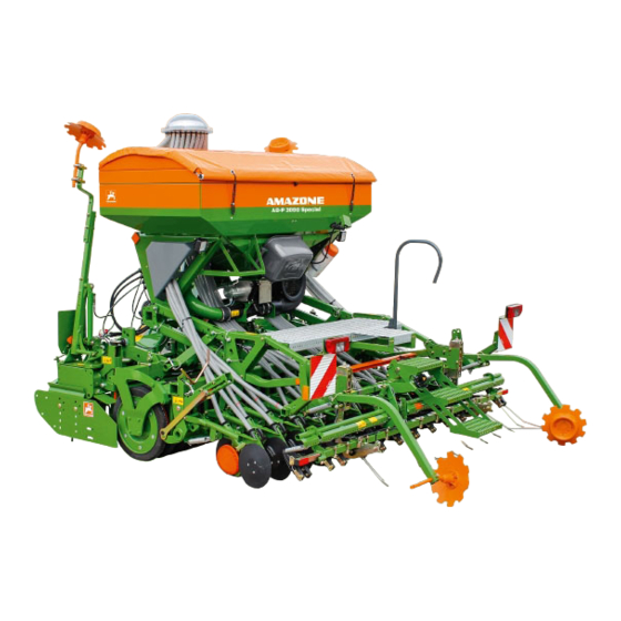
1000 l t2013gb03 Seed box, metering unit, distributor head and blower fan of the AD-P Special are fixed to the AMAZONE soil tillage implement with the aid of a coupling frame. The coulter frame rests on the strong roller. On AMAZONE combinations the seed placement depth remains the same even if the working depth of the soil tillage implement is changed. -
Page 9: Amazone Ws (Suffolk)-Coulter
2 - 3 AMAZONE WS (Suffolk)-coulter The AMAZONE WS-coulter (Fig. 2.2) is equipped with an exchangeable coulter tip (Fig. 2.2/1) made from cast iron. Due to its high wear resistance, cast iron is a proven coulter tip material. However, wear cannot be avoided during large area operation on aggressive, sandy and sharp edged soils. -
Page 10: Amazone-Sabre Coulter Tip (Option)
2 - 4 AMAZONE-sabre coulter tip (Option) The shallow angle of the AMAZONE sabre coulter tip (Fig. 2.4/1) allows a better straw passage. The larger surface of the coulter reduces the penetrating depth. That is why the sabre coulter tip can be used for a blockage-free mulch sowing in well mixed straw. -
Page 11: Amazone Rotec-Coulter
2 - 5 2.10 AMAZONE RoTeC-coulter The AMAZONE RoTeC-coulter (Fig. 2.5) optimises the sowing accuracy, area efficiency, and life time when sowing after the plough and mulch sowing. The steel disc (Fig. 2.5/1) is off set by only 7° as seen in the driven direction so that even at high forward speeds only a little soil is moved. -
Page 12: Hydraulic Circuit Diagram – Pack Top Seed Drill Ad-P Special
2 - 6 2.11 Hydraulic circuit diagram – Pack Top seed drill AD-P Special 25c026 Fig. 2.7 Description ab = implement side cd = tractor side Tractor control spool valves Q1 up to Q3 3 tractor control spool valves, illustrated in position ”operation” Permissible hydraulic oils HD-SAE 20W-20 according to MIL-L-2104 C or API- Q3 =... -
Page 13: Details About Noise Level
Declined use applies to damage due to sowing errors. Modifications of the machine made to the AMAZONE seed drill by the owner/user may result in damage and therefore the manufacturer does The AMAZONE-Pack Top Seed Drill AD-P Special has not accept liability for such damage. - Page 14 2 - 8 AD-P03 Special DB2013 09.02...
-
Page 15: Safety
Qualification of operator The AMAZONE-Pack Top Seed Drill AD-P Special may only be operated, maintained and repaired by persons, who are acquainted with it and have been informed of the relevant dangers. -
Page 16: Warning Pictographs And Hint Symbols On The Machine
3 - 2 Warning pictographs and hint symbols on the machine The warning pictographs (e.g. Fig. 3.1) indicate dangerous points on the machine. Observing these pictographs means safety to all persons using this machine. The hint symbols (e.g. Fig. 3.2) mark machine’s specific points which have to be observed to ensure correct function of the machine. - Page 17 3 - 3 The machine’s fixing points for the warning Please always keep all warning pictographs and hint pictographs and hint signs are illustrated in Fig. 3.3. signs clean and in readable condition. Please ask for Please refer to the following pages for relevant replacement of damaged or missing warning signs explanations.
- Page 18 3 - 4 Picture No.: MD 076 Explanation: Start operating the implement only with all guards fitted. Do not remove guards while the engine is running. Before removing the guards, switch off the PTO shaft and the engine, remove ignition key. Picture No.: MD 077 Explanation: Danger of bruising while machine is running.
- Page 19 3 - 5 Picture No.: MD 084 Explanation Never stay within the operational area of the marker arms. Picture No.: MD 095 Explanation Before starting operation read and observe instruction manual and safety advice. Picture No.: 951790 Explanation Retighten bolts frequently and after some hours of operation.
-
Page 20: Safety Conscious Operation
3 - 6 Safety conscious operation weights. Therefore, take account of these effects and allow for changes to the steering and to stopping In addition to the safety advice in this operation distances when braking. manual the national, and general operational safety 19. - Page 21 3 - 7 3.6.2 General safety and accident 3.6.3 General safety and prevention advice accident prevention advice regarding the implement mounted to regarding the operation of seed the tractors three-point linkage drills 1. Before mounting- and dismounting implements to 1. During calibration be aware of the danger created by the three-point-linkage bring all control levers into a by rotating and oscillating implement parts position so that unintentional lifting or lowering is...
- Page 22 3 - 8 3.6.4 General safety and accident 3.6.5 General safety and accident prevention advice preventive advice regarding the hydraulic system for PTO shaft operation 1. The hydraulic system is under high pressure! 2. When connecting hydraulic rams and motors the 1.
- Page 23 8. Any spare parts fitted, as a minimum requirement, must meet with the implement manufacturers’ fixed technical standards. This is, for example, ensured by using original AMAZONE spare parts. AD-P03 Special DB2013 09.02...
-
Page 24: Determination Of Total Weight, Axle Loads
3 - 10 Determination of total weight, axle loads, load capacity of the tyres as well as the required minimum ballast when combining tractor and mounted implement When mounting implements to the front or rear three point linkage the permissible total weight, the permissible axle loads and the load capacity of the tractor tyres 22c001... - Page 25 3 - 11 Rear mounted implement or front-rear mount combinations • (c + d) - T • b + 0,2 • T • b 1) Calculation (see Fig. 3.11) of minimum ballast V min front GV min Enter into table Fig. 3.16 the calculated minimum Fig.
- Page 26 3 - 12 Permissible value Double permissible Actual value according to instruction tyre load capacity Table according to calculation manual (two tyres) Minimum ballast Front / rear Total weight Front axle load Rear axle load Fig. 3.16 t178gb03 AD-P03 Special DB2013 09.02...
-
Page 27: Tractor And Mounted Implement
14.1. Attach the Pack Top seed drill to an AMAZONE soil tillage implement according to para. 5.0. Attach your Pack Top seed drill to the soil tillage AD-P03 Special DB2013 09.02... - Page 28 4 - 2 implement of another manufacturer according to para. 6.0. Attach blower fan with belt drive according to para. 7.0. Attach the hydraulic blower fan drive according to para. 8.0. Connect the connecting valve Q1 (Fig. 2.7) with hydrau- lic coupling (Fig.
-
Page 29: Setting Up The Machine In The Field
4 - 3 Determine the gearbox setting position for the desired seed rate according to para. 11.0. heck the hydraulic hoses before and during operation according to para. 18.7.1. Setting up the machine in the field Bring markers into operating position according to para. 12.1. -
Page 30: After The First 10 Hours
Raise the combination by using the tractor’s hydraulic system to attach the parking supports. Before parking the combination pull the depth setting pins (Fig. 4.7/1) of the AMAZONE soil tillage implement have off the setting quadrant brackets (Fig. 4.7/2). When reinserting the depth setting pins (Fig. -
Page 31: Mounting The Pack Top Seed Drill Ad-P Special Onto Rotary Harrows Ke And Rotary Cultivators Kg
5 - 1 Mounting the Pack Top seed drill AD-P Special onto rotary harrows KE and rotary cultivators KG Equipping wedge ring rollers KW580 and tyre packer rollers RP with coupling parts For coupling park the roller on level ground and care for a safe support (secure against falling over and rolling away). -
Page 32: Equipping Wedge Ring Roller Kw450 And
5 - 2 Equipping wedge ring roller KW450 and tooth packer roller PW500 with coupling parts For coupling park the roller on level ground and care for a safe support (secure against falling over and rolling away). Attach coupling parts (Fig. 5.5/1) by using clamps (Fig. 5.5/2) to the roller, directly beside the carrying arms (Fig. -
Page 33: Coupling The Ad-P Special
5 - 3 Coupling the AD-P SPECIAL Back up with the soil tillage implement to the seed drill (Fig. 5.8) parked on a level ground. Pick up the AD-P SPECIAL with the coupling frame (Fig. 5.9/1) and set the joint using a pin (Fig. 5.10/1). Secure using a lynch pin. - Page 34 5 - 4 Take the pin (Fig. 5.11) in your hand – when not in use insert the pin in the bracket (Fig. 5.11/1) – and secure the joint (Fig. 5.12) using pins and lynch pins. Connect the track marker sensor cable (Fig. 5.13). Align the Pack Top seed drill with the aid of the top link (Fig.
-
Page 35: Attaching Amazone-Pack Top Seed Drills Ad-P Special Onto Soil Tillage Implements Of Other Manufacturers
The soil tillage implement must be designed in such a way that it is strong enough to bear the additional load when the AMAZONE Pack Top seed drill AD-P Special is attached. Therefore the AMAZONE Pack Top seed drill AD-P Special can only be attached onto rotary harrows of Messrs. -
Page 36: Mounting The Pack Top Seed Drill Ad-P Special To Kuhn Rotary Harrow
6 - 2 Mounting the Pack Top seed drill AD-P Special to Kuhn rotary harrow Attach the supplied “AMAZONE mounting frame” onto the Kuhn rotary harrow. The rigging screws (Fig. 6.5/3) are fitted when your seed drill AD-P Special is supplied. -
Page 37: Basic Setting Of The Pack Top Seed Drill Ad-P Special
6 - 3 6.1.1 Basic setting of the Pack Top seed drill AD-P Special Before carrying out the following settings on the turn- buckles, set the desired working depth of the rotary harrow. Align the AD-P Special on the rotary harrow. The setting is done with the aid of the top link (Fig. -
Page 38: Mounting The Seed Drill Ad-P Special Onto Rotary Harrows From Messrs. Lemken/Maschio/Rabe
Mounting the Seed drill AD-P Special onto rotary harrows from Messrs. Lemken/Maschio/Rabe For mounting AMAZONE-seed drill AD-P Special, plea- se refer to rotary harrows from Messrs. Lemken (see Fig. 6.6) rotary harrows from Messrs. Maschio (see Fig. 6.7) rotary harrows from Messrs. Rabe (see Fig. 6.8) - Page 39 6 - 5 The rigging screws (Fig. 6.91) are fitted when your seed drill AD-P Special is supplied. Pick up the AD-P Special by using the mounting frame (Fig. 6.10). Slacken the M8 saucer head bolts (Fig. 6.11/2) and push the setting stand (Fig. 6.11/1) against the locking pin (Fig.
- Page 40 6 - 6 Affix the coulter frame closely behind the roller, howe- ver, ensure that coulter frame and roller do not touch. The distance can be varied by setting the coulter frame in one of the 3 (Fig. 6.12/1). After re-setting secure the pins by using clip pins.
-
Page 41: Blower Fan With Belt Drive
The blower fan of the AD-P SPECIAL can either be driven hydraulically or mechanically by a belt drive (only im combination with AMAZONE soil tillage implements). If the blower fan of the AD-P SPECIAL shall be driven by a belt drive, the gearbox of the rotary harrow or rotary cultivator has to be equipped with a PTO through drive (Fig. - Page 42 7 - 2 Set the V-belt tensioning by adjusting the V-belt pulley with a turnbuckle (Fig. 7.5/1). Secure setting with the previously slackened counter nut. In addition the V-belts are tensioned by a spring loaded tensioner (Fig. 7.6/1). After every setting affix the guard hood (Fig. 7.7/1) using hex.
-
Page 43: Handling The Taper Tensioning Bushings For V-Belt Pulleys
7 - 3 Handling the taper tensioning bushings for V-belt pulleys For mounting and dismounting the V-belt pulley an Allen key DIN 911 is required. Fixing a V-belt pulley with a taper tensioning bus- hing Clean all bright surfaces of the taper tensioning bushing (Fig. -
Page 44: Throttle Flap
7 - 4 Throttle flap On machines which are equipped with a belt drive the blower fan speeds cannot be changed. These machines are equipped with a throttle flap to reduce the rate of air flow. The throttle flap lever (Fig. 7.10/1) or the throttle flap can be set in two positions: open: (see Fig. -
Page 45: Blower Fan
8 - 1 Blower fan 956901 AD-P / AD-PL with hydraulic drive FRS / FPS The air flow for the seed delivery from the injector sluice AIRSTAR Xact to the coulters is provided by a blower fan which is driven by a hydro static motor (Fig. -
Page 46: Speed Monitoring
8 - 2 The blower fan speed is changing until the hydraulic oil has reached its operational temperature. At the first use the blower fan speed should be corrected until the operational temperature of the hydraulic oil has been reached. If the blower fan is used after a prolonged period of standstill, the reset blower fan speed will only be reached after the hydraulic oil has reached the operational temperature. -
Page 47: Circuit Diagram Blower Fan With Hydraulic Drive
8 - 3 Circuit diagram blower fan with hydraulic drive No Description Blower fan hydrostatic motor N = 4000 max. R.P.M. DBV-valve with hydr. free wheel Adjustable pressure relief valve Check valve Tractor hydraulic pump required capacity: minimum 40 l/min. at 150 bar Free return flow - tube nominal width min. - Page 48 8 - 4 The hydraulic oil must not heat up too much. If large amounts of oil are fed into small oil tanks, the hydraulic oil will heat up. The capacity of the oil tank (Fig. 8.6/9) should at lest have the double of the oil delivery amount. If the oil heats up too much, the installation of an oil cooler on the tractor by a professional workshop is necessary.
-
Page 49: Seed Box
9 - 1 Seed box filling and emptying Before filling the seed box couple the seed drill to the soil tillage implement. First empty the seed box before uncoupling the seed drill 24t088 Fig. 9.1 Filling the seed box The seed box can be filled from the loading platform (Fig. 9.2), with a shovel loader or with big bags. -
Page 50: Emptying The Seed Box
9 - 2 Emptying the seed box It is of great importance that the seed box and the seed metering wheels are cleaned after having finished operation. If the seed metering wheels are not empties completely, even there seed residue swells and germinates. -
Page 51: Setting The Metering Unit To A Particular Seed
10 - 1 10.0 Setting the metering unit Throttle- to a particular seed Seed flap- Metering wheel* position** Every metering unit is provided with a white coloured main seed wheel (Fig. 10.1/1) Beans open Main seed wheels an orange coloured main seed wheel (Fig. 10.1/2) Dinkle Main seed wheels open... -
Page 52: Switching
10 - 2 10.1 Switching the metering wheels on and off In the position “metering wheel on” (”Särad ein”) the knurled bolt (Fig. 10.3/1) is driven in till the stop. In the position metering wheel off” (“Särad aus”) the knurled bolt (Fig. 10.4/1) is driven out till the stop (Fig. 10.4/2). -
Page 53: Sowing
10 - 3 10.3 Sowing with the fine seed metering wheel 10w007 Fig. 10.6 When sowing with the fine seed metering wheel (Fig. 10.6/1) turn hand wheel (Fig. 10.7/1) until the knurled bolts (Fig. 10.7/2) can be seen drive in knurled bolt(Fig. 10.6/2) of the fine seed metering wheel drive out knurled bolts (Fig. - Page 54 10 - 4 AD-P03 Special DB2013 09.02...
-
Page 55: Determining The Gearbox Setting For The Desired Seed Rate
11 - 1 11.0 Determining the gearbox setting for the desired seed rate Set the metering unit according to para. 10.0. Fill the seed box with seed to at least 1/4 of its capacity. Set the desired seed rate on the gearbox (Fig. 11.1/1). By the gearbox setting lever (Fig. - Page 56 11 - 2 Place the calibration tray (Fig. 11.4) below the metering unit. The calibration tray (Fig. 11.5/1) is fixed in a retainer to the seed box and secured by a clip pin (Fig. 11.5/2). Open the injector sluice flap (Fig. 11.4/1). Slacken the star knob (Fig.
-
Page 57: Calibration Test
11 - 3 11.1 Calibration test Take the calibration crank in your hand. You will find the calibration crank (Fig. 11.7/1) in a retainer next to the vario gearbox. Insert the calibration crank (Fig. 11.8/1) into the take-up of the star wheel and turn the crank to the left until the/ all metering wheel housing(s) has/have been filled with seed and a uniform flow of seed runs into the calibration tray. - Page 58 11 - 4 The number of crank turns (Fig. 11.9) depends on the working width of your seed drill. The number of crank turns refers to an area of 1/40ha (250m ) or 1/10ha (1000m Common is the crank turn for 1/40 ha. In case of very 956268 small seed rates, e.g.
-
Page 59: Determining The Gearbox Setting With The Aid Of The Disc Rule
11 - 5 11.2 Determining the gearbox setting with the aid of the disc rule The desired seed rate usually is not obtained after the first calibration test. However, with the aid of the disc rule it is possible to determine the correct gearbox setting by using the gearbox setting figure of the first calibration test at the calculated seed rate. -
Page 60: Seed Rate Deviations Between The Setting And The Sowing
11 - 6 11.3 Seed rate deviations between the setting and the sowing To avoid deviations between the setting of the seed rate and the later sowing and to achieve a uniform distribution of the seed to all coulters, please note the following hints: When sowing dressed seeds The distributor head should regularly be checked and cleaned. -
Page 61: Track Marker
When the seed drill is operated in combination with an AMAZONE rotary cultivator/rotary harrow the track mark- ers (Fig. 12.2) are fixed on the soil tillage implement. When the seed drill is operated with a soil tillage... -
Page 62: Bring Markers
12 - 2 12.1 Bring markers into operating or transport position For transport, i.e. immediately after work, each marker arm (Fig. 12.4/2) is fixed with a pin (Fig. 12.4/1 or Fig. 12.5/1) and secured by using a clip pin (Fig. 12.6). Figure (Fig. - Page 63 12 - 3 Insert the pin in parking position (see Fig. 12.7 or Fig. 12.8) immediately prior to the operation in the field and secure using a clip pin. Figure (Fig. 12.7) illustrates how to insert the pin on the marker arm which is fixed to a rotary cultivator/rotary harrow.
-
Page 64: Setting The Marker Arms To The Correct Length
12 - 4 12.2 Setting the marker arms to the correct length The seed drill is equipped with markers for marking a trace in the soil in line with the tractors centre. The distance is measured either from the machine’s centre or from the outer sowing coulter (see Fig. -
Page 65: Obstacles In The Field
12 - 5 12.3 Obstacles in the field To avoid damage, the markers should be raised before hitting an obstacle in the field. Lower the marker down again after the obstacle has been passed, However, the two markers are linked in rhythm, so when actuating the tractor control spool valve, the opposite marker is lowe- red. - Page 66 12 - 6 AD-P03 Special DB2013 09.02...
-
Page 67: Setting The Placement Depth Of The Seed
13 - 1 13.0 Setting the placement depth of the seed One of the most important preconditions for high yields is maintaining a constant placement depth of the seed. The placement depth depends on coulter pressure, forward speed and soil condition. Your seed drill is equipped as standard with a central coulter pressure adjustment which applies an even pressure to all coul- ters. -
Page 68: Setting The Placement Depth Of The Seed By The Adjustment Spindle
13 - 2 13.1 Setting the placement depth of the seed by the adjustment spindle The coulter pressure and thus the placement depth of the seed is increased by turning the spindle (Fig. 13.3/ 1) clockwise, by turning it counter clockwise it is redu- ced. -
Page 69: Setting The Placement Depth
13 - 3 13.2 Setting the placement depth of the seed by a hydraulic ram (special option) The coulter pressure and thus the placement depth can centrally be set by a hydraulic ram (Fig. 13.6). During the operation the coulter pressure can be increased in areas with heavier soil. -
Page 70: Setting The Placement Depth Of The Seed By Resetting The Rotec Depth Limiting Discs (Special Option)
13 - 4 Seed drills with RoTeC-disc coulters When your seed drill is equipped with RoTeC-disc coulters and depth limiters (special option) and the desired placement depth cannot be achieved by repla- cing the pin, all RoTeC depth limiter discs would have to be re-adjusted evenly according to para. - Page 71 13 - 5 Setting the depth limiters The RoTeC-limiting disc (Fig. 13.12/1) can be set in 4 positions. For medium soils, the following placement depths (see Fig. 13.13) result: Positions 1: placement depth approx. 2cm Positions 2: placement depth approx. 3cm Positions 3: placement depth approx.
- Page 72 13 - 6 AD-P03 Special DB2013 09.02...
-
Page 73: Extra Coverage Following Harrow (Option)
14 - 1 14.0 Extra coverage following har- row (option) The extra coverage following harrow (Fig. 14.1) even- ly covers the seed with soil. 14.1 Mounting the extra coverage follo- wing harrow onto the seed drill Bolt on the swing metal buffer (Fig. 14.2/1). 11t004 Locate fixing tubes (Fig. -
Page 74: Connecting Hydraulic Ram (Option)
14 - 2 14.1.1 Connecting hydraulic ram (option) When supplied the hydraulic ram (Fig. 14.4/1) is fitted to the extra coverage following harrow. Connect the hydraulic hose (Fig. 14.4/2) with the hydraulic ram. Allow the hydraulic hose (Fig. 14.4/2) to have a sufficiently large loop in it when fitting to the pivoting points of the link arm of the extra coverage following harrow to... -
Page 75: Bring Outer Following Harrow Tines Into Operating Position
14 - 3 14.2 Bring outer following harrow tines into operating position During operation the packer roller and the coulters of the seed drill throw the soil in varying different di- stances to the sides, depending on the forward speed and the soil conditions. -
Page 76: Setting The Harrow Tine Pressure On The Extra Coverage Following Harrow With Hydraulic Ram
14 - 4 14.4 Setting the harrow tine pressure on the extra coverage following harrow with hydraulic ram Set the pressure by which the spring tines (Fig. 14.6/ 1) of the extra coverage following harrow are pres- sing on to the soil in such a way that after the seed has been covered no ridge remains visible in the field. -
Page 77: Road Transport
14 - 5 14.5 Road transport For transport on public roads, the outer square tubes (Fig. 14.9/1) carrying the outer harrow tines (Fig. 14.9/2) should be slid back into the centre carrier tube. Before you can do this, slacken clamping bolt (Fig. - Page 78 14 - 6 AD-P03 Special DB2013 09.02...
- Page 79 15 - 1 15.0 Creating tramlines with AMADOS/AMALOG-tramlining control Tramlines are marks (Fig. 15.1/1), in which no seed is sown. The husbandry tractor determines the track width. The spacing between the tramlines corresponds to the working width of the sprayer (Fig. 15.1/2) and of the centrifugal broadcaster.
-
Page 80: Amados/Amalog
15 - 2 When supplied, the tramline spacing of your implement has been set to the track width of your husbandry tractor according to your prior indication. An electric lifting spindle motor (Fig. 15.3/1) or a Bow- den control which is connected with the switch box, actuate the mechanism inside the tramline flap box (Fig. - Page 81 15 - 3 15.1 Starting the operation Take the "starting figure" from the tramline schedules (Fig. 15.5) and set the "starting figure" on the display of AMADOS/AMALOG prior to starting the operation. Example: "Starting figurel" of switching rhythm "3" In colum "C" move to figure "3" (switching rhythm 3). Change to column "D".
- Page 82 15 - 4 Fig. 15.5 AD-P03 Special DB2013 09.02...
- Page 83 15 - 5 15.2 Hints for creating tramlines with 4-, 6- and 8-fold switching rhythm Fig. 15.5 illustrates examples for creating tramlines with 4-, 6- and 8fold switching rhythms. The seed drill ope- rates with half its working width during the first run in the field.
- Page 84 15 - 6 15.3 Hints for creating tramlines with 2-fold and 6-plus switching rhythms Tramlines with 2-fold and 6-plus switchng rhythms (see Fig. 15.8) are created during one travel in the field to and fro. The flow of the seed to the tramline coulters must only be interrupted on seed drills 2-old switching rhythm on the right hand side of the seed drill...
- Page 85 15 - 7 15.4 Setting the tramline to the wheel marks of the husbandry tractor Tramlines are marks in which no seed is sown. The spacing of the marks corresponds to the track width of the husbandry tractor. On supply of the seed drill the tramline kit has been set to the wheel marks of your husbandry tractor.
- Page 86 15 - 8 Activate flap (for tramline coulter) Deactivate flap (for a normal sowing coulter) Every individual flap (Fig. 15.11/1) can be activated Every individual flap may be deactivated (Fig. 15.12/1). inside the flap box. In order to reach the flap, remove the In order to reach the flap, remove the relevant fitting relevant fitting window (Fig.
-
Page 87: Pre-Emergence Marker (Special Option)
16 - 1 16.0 Pre-emergence marker (special option) With the aid of the tramlining control, during sowing operation, tramlines are created with determined spa- cings in which lateron fertiliser broadcasters or field sprayers may travel. The marker discs (Fig. 16.1/1) of the pre-emergence marker mark these tramlines. -
Page 88: Fitting
16 - 2 16.1 Fitting The pre-emergence marker unit is delivered pre-as- sembled by the factory Guide the hydraulic hoses in such a way Attach the extra coverage following harrow that they will not be torn off or damaged by Attach two fixing brackets (Fig. -
Page 89: Setting The Marker Discs
16 - 3 16.2 Setting the marker discs The marker discs (Fig. 16.4/1) trace the tramlines crea- ted by the tramlining control unit and have to be set to the correct track width: Slacken hex. bolts (Fig. 16.4/2) Move the marker discs (Fig. 16.4/1) in the marker disc carrier arm corresponding to the track width of the tramlines. -
Page 90: Transport On Public Roads
16 - 4 16.3 Transport on public roads For transport the marker disc carriers (Fig. 16.5/1) should be locked on the fitting brackets (Fig. 16.5/2) by pins (Fig. 16.5/3) and secured by using clip pins (Fig. 16.5/4). The marker disc carriers (Fig. 16.5/1) are then completely folded upwards and are positioned with the marker discs vertically above the extra coverage follo- wing harrow. -
Page 91: Transport
17 - 1 17.0 Transport on public roads When travelling on public roads and ways the execution of tractor and machinery should correspond to the national road transport and traffic rules. Both, the vehicle owner and the operator, are responsible for adhering to the legal traffic rules. - Page 92 17 - 2 wheel in transport position (Fig. 17.3). Briefly lift the star wheel, push towards the implement’s centre and secure by using a lynch pin (Fig. 17.4/1). During operation insert the lynch pin into the second hole (Fig. 17.5/1). Soil tillage implement Also the soil tillage implement must correspond to the national legal traffic rules.
-
Page 93: Maintenance And Care
18 - 1 18.0 Maintenance and care Observe the general safety and accident prevention advice when carrying out maintenance and care. 18.1 Check bolted connections All bolted connections of the implement should be checked after the first 10 hours of operation and tighte- ned if necessary. -
Page 94: Checking The Oil Level In The Gearbox
18 - 2 18.3 Checking the oil level in the gear- The oil level inside the gearbox should be checked at the oil gauge window (Fig. 18.2/1) at the implement in horizontal position. It is not necessary to change the gearbox oil. -
Page 95: Checking The Distributor Head For Cleanliness
18 - 3 18.6 Checking the distributor head for cleanliness During operation regularly check from the tractor cab the distributor head for cleanliness by looking through the translucent distributor head hood and after operati- on from outside. Immediately remove dirt and seed residue. -
Page 96: Please Observe When Fitting And Removing
18 - 4 18.7.4 Please observe when fitting and removing Before working on the hydraulics, please read and adhere to para. 3.6.4. Affix the hydraulic hoses on the fixing points given by the manufacturer. Always ensure that hydraulic parts and connections are clean The hoses have to be fitted in such a way that their natural placement and movement are not hindered... - Page 97 18 - 5 AD-P03 Special DB2013 09.02...
- Page 98 18 - 6 AD-P03 Special DB2013 09.02...
- Page 100 D-27794 Hude/Oldbg. D-49202 Hasbergen-Gaste AMAZONE-Machines Agricoles S.A. Tel.: Hasbergen (0 54 05) *501-0 Tel.: Hude (0 44 08) *927-0 F- 57602 Forbach/France . rue de la Verrerie Fax: (0 54 05) 50 11 93 Fax: (0 44 08) 92 73 99 Tél.: (0033) 38 78 46 57 0...
Need help?
Do you have a question about the AD-P 03 SPECIAL and is the answer not in the manual?
Questions and answers