
Related Manuals for Amazone AmaSpread 2


Summary of Contents for Amazone AmaSpread 2
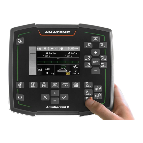
- Page 1 Original operating manual Control computer AmaSpread 2 This operating manual is valid as of software version NW355-B.009 SmartLearning www .amazone.de...
-
Page 3: Table Of Contents
TABLE OF CONTENTS TABLE OF CONTENTS Configuring the terminal 1 About this operating manual Diagrams 7 Adjusting the implement 1.1.1 Warnings and signal words 1.1.2 Further instructions Configuring the source for the speed signal 1.1.3 Instructions 7.1.1 Configuring the speed signal from 1.1.4 Lists the tractor... - Page 4 TABLE OF CONTENTS 11.7 Using the work lights 12 Emptying the hopper 13 Documenting work 14 Calling up information 15 Repairing the implement 15.1 Calibrating the shutters 15.2 Taring the scale 15.3 Adjusting the scale 15.4 Display diagnosis data 16 Troubleshooting 17 Appendix 17.1 Other applicable documents...
-
Page 5: About This Operating Manual
1 | About this operating manual About this operating manual CMS-T-00000081-D.1 1.1 Diagrams CMS-T-005676-C.1 1.1.1 Warnings and signal words CMS-T-00002415-A.1 Warnings are marked with a vertical bar with a triangular safety symbol and the signal word. The signal words "DANGER", "WARNING" or "CAUTION" describe the severity of the potential danger and have the following meanings: DANGER... -
Page 6: Instructions
1 | About this operating manual Diagrams ENVIRONMENTAL INFORMATION Indicates a risk for environmental damage. NOTE Indicates application tips and instructions for optimal use. 1.1.3 Instructions CMS-T-00000473-B.1 Numbered instructions CMS-T-005217-B.1 Actions that have to be performed in a specific sequence are represented as numbered instructions. The specified sequence of the actions must be observed. -
Page 7: Lists
1 | About this operating manual Diagrams Example: 1. Instruction 1 Alternative instruction 2. Instruction 2 Instructions with only one action CMS-T-005211-C.1 Instructions with only one action are not numbered, but rather shown with a arrow. Example: Instruction Instructions without sequence CMS-T-005214-C.1 Instructions that do not require a specific sequence are shown as a list with arrows. -
Page 8: Other Applicable Documents
Your suggestions for improvement help us Technische Redaktion to create ever more user-friendly operating manuals. Postfach 51 Please send us your suggestions by post, fax or D-49202 Hasbergen email. Fax: +49 (0) 5405 501-234 E-Mail: td@amazone.de MG7387-EN-II | B.1 | 12.01.2022... -
Page 9: Safety And Responsibility
2 | Safety and responsibility Safety and responsibility CMS-T-00004961-B.1 2.1 Road traffic CMS-T-00003620-C.1 Do not use the control computer or control terminal during road travel If the driver is distracted, it can result in accidents and injuries or even death. Do not operate the control computer or control terminal during road travel. -
Page 10: Design Changes
2 | Safety and responsibility Design changes Improper cleaning can cause damage Clean the control computer or control terminal only with a moist, soft cloth. Incorrect operating temperature and storage temperature can cause damage If the operating temperature and storage temperature are not observed, there can damage to the control computer or control terminal, therefore resulting in malfunctions and dangerous... -
Page 11: Display
2 | Safety and responsibility Display 2.4 Display CMS-T-00003624-B.1 Risk of accident due to faulty display screens If the display is faulty or the view on the screen is limited, functions can be accidentally activated and therefore trigger implement functions. This can result in injury or death. -
Page 12: Intended Use
3 | Intended use Intended use CMS-T-00005429-B.1 The control computer is used to control agricultural implements. The operating manual is part of the control computer. The control computer is solely intended for use in compliance with this operating manual. Uses of the control computer that are not described in this operating manual can lead to serious personal injuries or even death and to implement and material damage. -
Page 13: Product Description
4 | Product description Product description CMS-T-00008270-B.1 4.1 Function of the control computer CMS-T-00008235-B.1 The AmaSpread 2 control computer controls the implement functions and serves as a display terminal. The control computer offers the following functions: Starting or stopping fertiliser spreading... -
Page 14: Overview Of The Control Computer
4 | Product description Overview of the control computer 4.2 Overview of the control computer CMS-T-00008793-B.1 CMS-I-00006023 Work lights Switching on and off Display Input and navigation Menu selection Work menu 4.3 Menu selection CMS-T-00008246-B.1 Various data is shown in the menus. The data can be adjusted. - Page 15 4 | Product description Menu selection DOCUMENTATION The "Documentation" menu shows the work data. CMS-I-00006025 FERT. Calcium cyanamide The "Products" menu shows the product Application rate data and enables product-specific implement settings. Calibration factor Working width Other fertiliser settings CMS-I-00006026 The "Scale"...
- Page 16 4 | Product description Menu selection HOPPER The "Hopper" menu contains "Filling", Filling "Emptying" and "Tilting", if a tilt sensor is installed. Emptying Tilting CMS-I-00006057 IMPLEMENT The "Implement" menu enables implement Speed settings. Low level and rate control Terminal CMS-I-00006056 IMPLEMENT The second page of the "Implement"...
-
Page 17: Buttons
4 | Product description Buttons 4.4 Buttons CMS-T-00008247-B.1 4.4.1 Input keys and navigation keys CMS-T-00008248-A.1 Increase value or navigate upwards in the list Reduce value or navigate downwards in the list Cancel input or back to the previous menu CMS-I-00006030 Confirm 4.4.2 Function keys in the Work menu CMS-T-00008249-B.1... -
Page 18: Work Display
4 | Product description Work display Increase the spread rate on both Reduce the spread rate on both Set the spread rate to 100 % sides by the rate increment sides by the rate increment Switch on part-width Switch off part-width Switch on part-width Switch off part-width sections from the left... - Page 19 4 | Product description Work display Spread rate on the left 10 Automatic calibration switched on Spread rate on the left in % 11 Calibration factor Spread rate on the right 12 Hopper fill level Spread rate on the right in % 13 Spreading method Spread fan on the left 14 Spreading disc speed...
-
Page 20: Connecting The Control Computer
5 | Connecting the control computer Connecting the control computer CMS-T-00008829-B.1 1. Place the control computer on the holder 3 in the tractor cab. Imp./100m 2. Connect the connection cable 1 to the tractor power supply. 12 V 3. Connect the connection cable 1 to the control computer. -
Page 21: Basic Operation
6 | Basic operation Basic operation CMS-T-00008273-B.1 6.1 Switching the control computer on and off CMS-T-00008830-B.1 To switch on the control computer, press and hold the on/off button An acoustic warning signal is emitted. To switch off the control computer, press and hold the on/off button 6.2 Navigating in the menu CMS-T-00008831-B.1... -
Page 22: Entering Numerical Values
6 | Basic operation Entering numerical values Confirm the selection. Cancel the selection or exit the menu. To change the menu page, select the page display and confirm. Page 1 will be shown. Page 2 will be shown. Page 3 will be shown. CMS-I-00006082 6.3 Entering numerical values CMS-T-00008850-A.1... -
Page 23: Configuring The Terminal
6 | Basic operation Configuring the terminal 6.4 Configuring the terminal CMS-T-00008854-B.1 The following parameters can be set: Region and language Display illumination Speed Delete saved pool Call up "Implement" menu. 2. Select "Terminal". MG7387-EN-II | B.1 | 12.01.2022... -
Page 24: Adjusting The Implement
7 | Adjusting the implement Adjusting the implement CMS-T-00008277-B.1 7.1 Configuring the source for the speed signal CMS-T-00008860-B.1 7.1.1 Configuring the speed signal from the tractor CMS-T-00008864-B.1 IMPLEMENT Call up "Implement" menu. Speed 2. Select "Terminal". Low level and rate control Terminal CMS-I-00006087 To be able to select the "Signal socket"... -
Page 25: Determining The Pulses Per 100 M
7 | Adjusting the implement Configuring the source for the speed signal To control electric metering drives, a speed signal is IMPLEMENT required. A speed signal from the tractor can be used for this. Speed To configure the "Speed signal", Low level and rate control Call up "Implement"... -
Page 26: Entering The Simulated Speed
7 | Adjusting the implement Configuring the source for the speed signal 5. Drive to the end point. The "Driven pulses" will be counted. 6. Select "Continue". CMS-I-00005019 To accept the value, select "Save" To discard the value, select CMS-I-00005020 7.1.3 Entering the simulated speed CMS-T-00008861-A.1 To control electric metering drives, a speed signal is... -
Page 27: Configuring The Low Level Notification
7 | Adjusting the implement Configuring the low level notification 4. Under "Source", select "Simulated". Speed 5. Under "Simulated speed", enter the desired Source speed. Sensor configuration Simulated speed CMS-I-00006086 7.2 Configuring the low level notification CMS-T-00008865-A.1 IMPLEMENT Call up "Implement" menu. Speed 2. -
Page 28: Aligning The Implement Horizontally
7 | Adjusting the implement Aligning the implement horizontally 3. Enter the "Rate increment" for the percent change LOW LEVEL in the spread rate. Notification when hopper empty Fill level alarm limit Quantity increments CMS-I-00006089 7.4 Aligning the implement horizontally CMS-T-00008252-A.1 If the implement is equipped with a tilt sensor, the TILT... -
Page 29: Managing Products
8 | Managing products Managing products CMS-T-00008271-B.1 8.1 Creating a new product CMS-T-00008889-B.1 Each product can be recorded with a name and date. A maximum of 6 products can be created on 3 pages. 1. Park the tractor on a level surface with solid FERT. -
Page 30: Selecting Or Deleting A Product
8 | Managing products Selecting or deleting a product 8.2 Selecting or deleting a product CMS-T-00009043-B.1 SELECT FERTILIS. Call up the "Product" menu. Calcium cyanamide Select the product list. Fertiliser 3. Scroll if necessary. 4. Select the product and confirm. CMS-I-00006133 5. - Page 31 8 | Managing products Entering the product data 9. Enter the "Spreading disc nominal speed" from SPREADER UNIT the setting chart. Spreading disc nominal speed 10. Enter the "Spreading vane position" from the setting chart for the long and short spreading Spreading vane position vane.
-
Page 32: Filling The Hopper
9 | Filling the hopper Filling the hopper CMS-T-00008267-B.1 Call up the "Hopper" menu. 2. Select "Filling". 3. Enter the "Target fill level". 4. Fill the implement until the target fill level has CMS-I-00006090 been reached. NOTE If the work lights are installed, the spread fan illumination indicates the current target fill level during the filling procedure. -
Page 33: Determining The Calibration Factor At A Standstill
10 | Determining the calibration factor at a standstill Determining the calibration factor at a standstill CMS-T-00008892-B.1 1. Keep the spreading disc drive switched off. 2. Remove the spreading discs. 3. Install the calibration chute on the left spreading disc. 4. - Page 34 10 | Determining the calibration factor at a standstill 17. Switch on the spreading disc drive. 18. Open the left shutter. When the collection bucket is full, close the left shutter. Switch off the spreading disc drive. 21. Weigh the collected quantity. CMS-I-00006174 22.
-
Page 35: Working
11 | Working Working CMS-T-00008274-B.1 11.1 Spreading fertiliser CMS-T-00008257-B.1 Shutter open Shutter closed CMS-I-00006176 REQUIREMENTS The implement is configured The product data is entered The product is selected The weighing method for determining the calibration factor is selected Alternative: Determine the calibration factor at a standstill before operation Call up the "Work"... -
Page 36: Determining The Calibration Factor Manually While Driving
11 | Working Determining the calibration factor manually while driving When the switch-off point according to the setting chart has been reached, close the shutter. When work is finished, stop the spreading disc drive. 11.2 Determining the calibration factor manually while driving CMS-T-00008977-B.1 Call up the "Scale"... -
Page 37: Spreading On One Side
11 | Working Spreading on one side 11. Save the calibration factor Cancel. To optimise the calibration factor, repeat the calibration run. CMS-I-00006218 11.3 Spreading on one side CMS-T-00008258-A.1 Left shutter open Right shutter open CMS-I-00006182 Open and close the left shutter Open and close the right shutter. -
Page 38: Switching Part-Width Sections
11 | Working Switching part-width sections kg/ha kg/ha To increase the spread rate on the left by the rate increment, press and hold the button. CMS-I-00006220 To reduce the spread rate on the left by the rate increment, press and hold the button To increase the spread rate on the right by the rate increment, press and hold the button... -
Page 39: Boundary Spreading
11 | Working Boundary spreading 11.6 Boundary spreading CMS-T-00008259-B.1 The boundary spreading method can be selected before beginning operation or can be switched on and off during operation. The boundary spreading can be adjusted via the tilt adjustment of the boundary spread deflector. The selected boundary spreading method is shown with the LED light. -
Page 40: Using The Work Lights
11 | Working Using the work lights 1. Select the boundary spreading method. To increase the working width on the boundary side, raise the boundary spread deflector. To reduce the working width on the boundary side, lower the boundary spread deflector. The changed tilt of the boundary spread deflector is saved in the Product menu. -
Page 41: Emptying The Hopper
12 | Emptying the hopper Emptying the hopper CMS-T-00008276-A.1 1. Remove the spreading discs. Call up the "Hopper" menu. 3. Select "Emptying". Open the shutter. CMS-I-00006193 5. Switch on spreading disc drive if necessary. The agitator movement supports the emptying process. -
Page 42: Documenting Work
13 | Documenting work Documenting work CMS-T-00008272-A.1 The following work data will be documented and displayed: Daily data DOCUMENTATION Total data Working time Spread quantity Worked area CMS-I-00006192 Call up the "Documentation" menu. Delete the daily data. MG7387-EN-II | B.1 | 12.01.2022... -
Page 43: Calling Up Information
14 | Calling up information Calling up information CMS-T-00008265-B.1 INFO Call up "Implement" menu. Software 2. Select "Info". Counter readings To call up the software information or the implement identification number, Diagnostics select "Software". To call up the counter readings for the CMS-I-00006195 implement, select "Counter readings". -
Page 44: Repairing The Implement
15 | Repairing the implement Repairing the implement CMS-T-00008266-B.1 15.1 Calibrating the shutters CMS-T-00008967-B.1 After a software update, the calibration position on the left and right can be entered. 1. Write down the values before performing the update. 2. Unhook the pin from the motor 1 on the left and right shutter. -
Page 45: Taring The Scale
15 | Repairing the implement Taring the scale 12. Save the new calibration position. TEACH-IN PULSES Left Right Current values Calibration positions Save calibration positions? Save CMS-I-00006196 15.2 Taring the scale CMS-T-00008968-B.1 When the hopper is empty, the scale must display a fill level of 0 kg. -
Page 46: Display Diagnosis Data
15 | Repairing the implement Display diagnosis data 4. Drive the tractor with the implement onto a level surface with solid ground and wait until the scale comes to a rest. 5. Enter the weight of the filled fertiliser quantity. 6. -
Page 47: Troubleshooting
16 | Troubleshooting Troubleshooting CMS-T-00008989-B.1 Error code Errors Cause Solution F45001 Left limiter sensor failed The signal from the path Eliminate damage or measurement system of the interruptions on the cable linear drive for the left limiter to the linear drive. is less than 0.5 V. - Page 48 16 | Troubleshooting Error code Errors Cause Solution F45012 Right shutter is not The measured value of the see page 47 responding sensor on the right shutter does not change although the setting motor of the shutter has been switched on. F45015 Left shutter angle sensor The signal from the angle...
- Page 49 Refill the hopper hopper set by the user has been reached. F45058 The selected source for the The AmaSpread 2 terminal is Select an existing source. forward speed is not available not receiving a speed signal. Activate the speed signal in the terminal settings.
- Page 50 16 | Troubleshooting 16.1 F45003: Setpoint value cannot be maintained CMS-T-00008994-A.1 The desired spread rate cannot be spread with the working width and speed. 1. Reduce speed. 2. Reduce spread rate. 3. Reduce the working width 16.2 F45004: Left limiter is not responding CMS-T-00008999-A.1 Although the linear drive on the left limiter is switched on, the voltage value of the path measurement system in this drive does not change.
- Page 51 16 | Troubleshooting 16.4 F45010: Left shutter is not responding CMS-T-00008996-A.1 The measured value of the sensor on the left shutter does not change, although the setting motor of the shutter has been switched on. 1. Eliminate any damage or interruptions on the cable connection to the setting motor.
- Page 52 16 | Troubleshooting 16.8 F45063: Setpoint value cannot be maintained CMS-T-00009027-A.1 The desired spread rate cannot be spread with the working width and speed. 1. Reduce speed. 2. Reduce spread rate. 3. Reduce the working width. 16.9 F45069: Recurring error when determining the calibration factor CMS-T-00009002-A.1 During the automatic calibration, the newly calculated calibration factor was below 0.5 twice.
-
Page 53: Appendix
17 | Appendix Appendix CMS-T-00008986-A.1 17.1 Other applicable documents CMS-T-00008987-A.1 Tractor operating manual Operating manual for the mounted spreader MG7387-EN-II | B.1 | 12.01.2022... -
Page 54: Directories
18 | Directories Directories 18.1 Glossary CMS-T-00008275-A.1 Machine Mounted implements are accessory parts of the tractor. However, mounted implements are always referred to as the implement in this operating manual. Operating materials Operating materials serve to ensure operational readiness. Operating materials include e.g. cleaning agents and lubricants such as lubricating oil, greases or cleaners. -
Page 55: Index
18 | Directories Index 18.2 Index Address Intended use Technical editing Keys Basic information Input Navigation 13, 17 Boundary spread deflector Overview Adjusting the tilt Boundary spreading method Select Low level Configuring notifications Calibration factor determining at a standstill Menu selection determining while driving Documentation Select method... - Page 56 18 | Directories Index Rate increment entering Scale adjusting taring Shutter calibration Software Calling up the identification number Source of the speed signal Determining the pulses per 100 m Signal socket Speed entering Spreader emptying Spreading one-sided Selecting the boundary spreading method Spread rate adjusting Switching off...
- Page 58 AMAZONEN-WERKE H. DREYER SE & Co. KG Postfach 51 49202 Hasbergen-Gaste Germany +49 (0) 5405 501-0 amazone@amazone.de www.amazone.de MG7387-EN-II | B.1 | 12.01.2022...
Need help?
Do you have a question about the AmaSpread 2 and is the answer not in the manual?
Questions and answers