
Subscribe to Our Youtube Channel
Related Manuals for Amazone Avant 6002-2


Summary of Contents for Amazone Avant 6002-2
- Page 1 Original operating manual Mounted seeding combination Avant 6002-2 seeding unit SmartLearning www .amazone.de...
- Page 2 Please enter the identification data of the implement. The identification data can be found on the rating plate.
-
Page 3: Table Of Contents
TABLE OF CONTENTS TABLE OF CONTENTS Lighting and identification to the 1 About this operating manual rear Diagrams 4.10 Electronic drive monitoring 1.1.1 Warnings and signal words 4.11 Transport frame 1.1.2 Further instructions 4.12 Additional license plate 1.1.3 Instructions 4.13 Segment distributor head 1.1.4 Lists... - Page 4 TABLE OF CONTENTS 6.2.7 Installing the lighting on the seeding Turning on the headlands unit Preparing the implement for 8 Parking the machine operation 6.3.1 Adjusting the working position sensor 51 Parking the TwinTeC coulter 6.3.2 Folding the lighting Disconnecting the supply lines from the hose package 6.3.3 Unfolding the implement...
- Page 5 TABLE OF CONTENTS Cleaning the machine 10 Loading the machine 10.1 Lashing the machine 10.2 Lifting the implement 11 Appendix 11.1 Bolt tightening torques 11.2 Other applicable documents 12 Directories 12.1 Glossary 12.2 Index MG6545-EN-II | B.1 | 22.07.2021...
-
Page 7: About This Operating Manual
1 | About this operating manual About this operating manual CMS-T-00000081-D.1 1.1 Diagrams CMS-T-005676-C.1 1.1.1 Warnings and signal words CMS-T-00002415-A.1 Warnings are marked with a vertical bar with a triangular safety symbol and the signal word. The signal words "DANGER", "WARNING" or "CAUTION" describe the severity of the potential danger and have the following meanings: DANGER... -
Page 8: Instructions
1 | About this operating manual Diagrams ENVIRONMENTAL INFORMATION Indicates a risk for environmental damage. NOTE Indicates application tips and instructions for optimal use. 1.1.3 Instructions CMS-T-00000473-B.1 Numbered instructions CMS-T-005217-B.1 Actions that have to be performed in a specific sequence are represented as numbered instructions. The specified sequence of the actions must be observed. -
Page 9: Lists
1 | About this operating manual Diagrams Example: 1. Instruction 1 Alternative instruction 2. Instruction 2 Instructions with only one action CMS-T-005211-C.1 Instructions with only one action are not numbered, but rather shown with a arrow. Example: Instruction Instructions without sequence CMS-T-005214-C.1 Instructions that do not require a specific sequence are shown as a list with arrows. -
Page 10: Other Applicable Documents
Your suggestions for improvement help us Technische Redaktion to create ever more user-friendly operating manuals. Postfach 51 Please send us your suggestions by post, fax or D-49202 Hasbergen email. Fax: +49 (0) 5405 501-234 E-Mail: td@amazone.de MG6545-EN-II | B.1 | 22.07.2021... -
Page 11: Safety And Responsibility
2 | Safety and responsibility Safety and responsibility CMS-T-00004920-B.1 2.1 Basic safety instructions CMS-T-00004921-B.1 2.1.1 Meaning of the operating manual CMS-T-00006180-A.1 Observe the operating manual The operating manual is an important document and a part of the implement. It is intended for the user and contains safety-related information. - Page 12 2 | Safety and responsibility Basic safety instructions the machine must meet the following minimum requirements: The person is physically and mentally capable of controlling the machine. The person can safely perform work with the machine within the scope of this operating manual.
- Page 13 2 | Safety and responsibility Basic safety instructions Farmers can be e.g.: Farmers with higher education or training from a technical college Farmers by experience (e.g. inherited farm, comprehensive practical knowledge) Contractors who work by order of farmers Activity example: Safety training for agricultural helpers 2.1.2.1.4 Agricultural helpers CMS-T-00002313-A.1...
- Page 14 2 | Safety and responsibility Basic safety instructions 2.1.2.3 Danger for children CMS-T-00002308-A.1 Danger for children Children cannot assess dangerous situations and can behave unpredictably. As a result, children are at a higher risk. Keep children away. When you drive out or actuate machine movements, make sure that there are no children in the danger area.
- Page 15 2 | Safety and responsibility Basic safety instructions Observe the technical limit values Non-observance of the technical limits values of the machine can result in accidents and serious personal injury or even death. Moreover, the machine can be damaged. The technical limit values can be found in the Technical Data.
-
Page 16: Knowing And Preventing Dangers
2 | Safety and responsibility Basic safety instructions 2.1.2.4.3 Warning symbols CMS-T-00002317-B.1 Keep warning symbols legible Warning symbols on the machine warn you of risks in danger areas and are an important element of the machine's safety equipment. Missing warning symbols increase the risk of serious and lethal personal injury. - Page 17 2 | Safety and responsibility Basic safety instructions 2.1.3.2 Danger areas CMS-T-00004923-A.1 Dangers areas on the machine The following basic dangers are encountered in the danger areas: The implement and its work tools move during operation. Hydraulically raised machine parts can descend unnoticed and slowly.
-
Page 18: Safe Operation And Handling Of The Machine
2 | Safety and responsibility Basic safety instructions 2.1.4 Safe operation and handling of the machine CMS-T-00002304-G.1 2.1.4.1 Coupling implements CMS-T-00002320-C.1 Coupling the implement to the tractor Incorrectly coupling of the implement to the tractor results in hazards that can cause serious accidents. - Page 19 2 | Safety and responsibility Basic safety instructions 2.1.4.2 Driving safety CMS-T-00002321-D.1 Risk when driving on roads and fields Any mounted or towed implement as well as front or rear ballast weights on the tractor influence the driving behaviour and the steering and braking power of the tractor.
- Page 20 2 | Safety and responsibility Basic safety instructions Preparing the machine for road travel If the machine is not properly prepared for road travel, it can result in serious traffic accidents. Check the lighting and identification for road travel for proper function. Remove coarse dirt from the implement.
-
Page 21: Safe Maintenance And Modification
To ensure that the operating permit remains valid in accordance with national and international regulations, ensure that the specialist workshop only uses conversion parts, spare parts and special equipment approved by AMAZONE. MG6545-EN-II | B.1 | 22.07.2021... - Page 22 2 | Safety and responsibility Basic safety instructions 2.1.5.2 Work on the machine CMS-T-00002323-C.1 Only work on the machine when it is at a standstill If the machine is not standing still, part can move unintentionally or the machine can be set in motion.
- Page 23 2 | Safety and responsibility Basic safety instructions Maintenance work Improper maintenance work, particularly on safety-related components, endangers operational safety. This can result in accidents and serious personal injury or even death. Safety-related components include, for example, hydraulic components, electronic components, frames, springs, trailer coupling, axles and axle suspensions, lines and tanks containing flammable substances.
- Page 24 Before welding on the implement, uncouple the implement from the tractor. 2.1.5.3 Operating materials CMS-T-00002324-C.1 Unsuitable operating materials Operating materials that do not meet AMAZONE requirements can cause implement damage and accidents. Only use operating material that meet the requirements in the Technical Data.
-
Page 25: Safety Routines
CMS-T-00002325-B.1 Special equipment, accessories, and spare parts Special equipment, accessories, and spare parts that do not meet AMAZONE requirements can impede the operational safety of the implement and cause accidents. Only use original parts or parts that meet AMAZONE requirements. - Page 26 2 | Safety and responsibility Safety routines Securing the machine After uncoupling, the implement has to be secured. If the implement and implement parts are not secured, there is a risk of personal injury due to crushing and cutting. Only park the implement on stable and level ground.
- Page 27 2 | Safety and responsibility Safety routines Climbing on and off Negligent behaviour while climbing on and off can cause people to fall off the ladder. People who climb onto the machine without using the intended access steps can slip, fall, and suffer severe injury.
-
Page 28: Intended Use
Further instructions for intended use in special cases can be requested from AMAZONE. Uses other than those specified under the intended use are considered as improper. The manufacturer is not liable for any damage resulting from improper use, solely the operator is responsible. -
Page 29: Product Description
4 | Product description Product description CMS-T-00004321-B.1 4.1 Implement overview CMS-T-00004326-B.1 CMS-I-00003126 Rating plate on the implement Work lights Distributor heads Additional license plate 10 Placement depth adjustment Road safety bars in parking position 11 Coulter pressure adjustment Rear-facing lighting in parking position 12 Threaded cartridge Tramline marker 13 Job computer... -
Page 30: Function Of The Implement
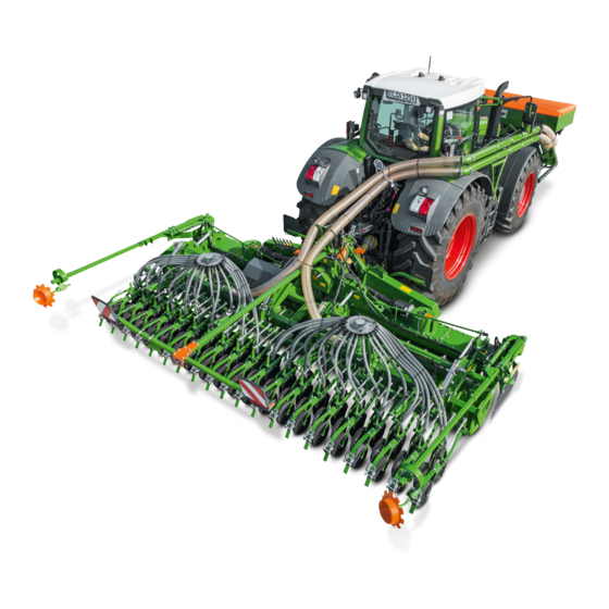
4 | Product description Function of the implement 4.2 Function of the implement CMS-T-00004333-B.1 CMS-I-00003159 The implement can only be used with a suitable soil tillage implement 5 . The combination enables seedbed preparation and seeding in one field pass. The metered material is carried with the FTender front hopper 1 and is metered into the conveyor section. -
Page 31: Protective Equipment
4 | Product description Protective equipment Hydraulic coulter pressure adjustment Coulter harrow Exact following harrow Exact following harrow lift Hydraulic exact following harrow pressure adjustment Seed tube monitoring 4.4 Protective equipment CMS-T-00004322-A.1 4.4.1 Road safety bars CMS-T-00000612-C.1 To protect from injuries during road transport, the road safety bar covers the tines on the rear harrow. -
Page 32: Warning Symbols
4 | Product description Warning symbols 4.5 Warning symbols CMS-T-00004330-B.1 4.5.1 Positions of the warning symbols CMS-T-00004331-B.1 CMS-I-00003265 4.5.2 Layout of the warning symbols CMS-T-000141-D.1 Warning symbols indicate danger areas on the machine and warn against residual dangers. In these danger areas, there are permanent or unexpected dangers. -
Page 33: Description Of The Warning Symbols
4 | Product description Warning symbols 4.5.3 Description of the warning symbols CMS-T-00004332-B.1 MD 078 Risk of crushing fingers or hands As long as the tractor engine or implement motor is running, stay away from the danger area. If you have to move marked parts with your hands, pay attention to the crushing areas. -
Page 34: Threaded Cartridge
4 | Product description Threaded cartridge 4.6 Threaded cartridge CMS-T-00001776-B.1 The threaded cartridge contains the following items: Documents Aids CMS-I-00002306 4.7 Mounting frame CMS-T-00004327-A.1 The seeding rail is fastened with the mount 1 on the roller frame of the carrying implement 2 . Each seeding rail has 2 mounts. -
Page 35: Universal Operating Tool
4 | Product description Universal operating tool 4.8 Universal operating tool CMS-T-00001735-B.1 Setting work on the implement is performed with the universal operating tool 1 . The universal operating tool is parked in a holder on the implement frame. CMS-I-00001082 4.9 Lighting and identification to the rear CMS-T-00001498-C.1 Warning signs... -
Page 36: Electronic Drive Monitoring
4 | Product description Electronic drive monitoring 4.10 Electronic drive monitoring CMS-T-00004030-A.1 The seeding rail monitors the drive of the rotary cultivator. Sensors 1 on both angular gearboxes 2 detect deviations in the gearbox speeds. If the gearbox speeds differ from one another or the tool carriers are blocked, the control computer issues an alarm with a notification on the display and an acoustic signal. -
Page 37: Additional License Plate
4 | Product description Additional license plate 4.12 Additional license plate CMS-T-00003999-B.1 Licence plate lighting Licence plate holder CMS-I-00003163 4.13 Segment distributor head CMS-T-00004345-B.1 The metered material is distributed to all of the coulters in the segment distributor head 1 . The distributor head has segments 2 , to which the seed line tubes 3 are connected. -
Page 38: Twintec Coulter
4 | Product description TwinTeC coulter 4.14 TwinTeC coulter CMS-T-00004346-B.1 The TwinTeC coulter is a double disc coulter and it deposits seed and fertiliser on ploughed or mulched soil. The concave discs 2 form the seed furrow. The metered material is guided between the concave discs and falls into the seed furrow. -
Page 39: Coulter Harrow
4 | Product description Coulter harrow The Control 10 depth control disc 1 has a 10 mm- wide contact area and is used on heavy soils. CMS-I-00004585 4.16 Coulter harrow CMS-T-00006648-A.1 The harrow tines 1 of the coulter harrow cover the deposited metered material evenly with loose soil. -
Page 40: Exact Following Harrow
4 | Product description Exact following harrow 4.17 Exact following harrow CMS-T-00006330-A.1 The harrow tines 2 of the exact following harrow rest horizontally on the ground and cover the deposited metered material evenly with loose soil. The position of the harrow tines can be adjusted. The exact following harrow pressure determines the tillage intensity of the exact following harrow. -
Page 41: Work Lights
4 | Product description Work lights For road travel, all sections 2 are folded and secured with a pin 1 . CMS-I-00003172 4.19 Work lights CMS-T-00004348-B.1 The work floodlights 1 make the working area more visible in the dark. The work floodlights are switched via the control terminal. -
Page 42: Rating Plate On The Implement
Year of manufacture CMS-I-00004294 4.21 mySeeder app CMS-T-00006215-A.1 The AMAZONE mySeeder app enables convenient handling of the implement using a mobile device. The implement can be connected to a mobile end device via Bluetooth and exchange data with the mySeeder app. -
Page 43: Technical Data
5 | Technical data Technical data CMS-T-00004349-B.1 5.1 Dimensions CMS-T-00004352-B.1 Avant 6002-2 seeding unit Dimensions with RoTeC coulters with TwinTeC coulters Transport width 2.9 m Transport height (seeding combination with running gear and 3.9 m track marker) Total length (seeding combination with running gear and track 3.8 m... -
Page 44: Optimal Working Speed
TwinTeC coulter 8-12 km/h RoTeC coulter 6-12 km/h 5.5 Performance characteristics of the tractor CMS-T-00004353-B.1 Type Engine rating Avant 6002-2 seeding unit Starting at 176 kW / 240 HP Electrical system Battery voltage 12 V Lighting socket 7-pin Hydraulic system... -
Page 45: Drivable Slope Inclination
5 | Technical data Drivable slope inclination 5.7 Drivable slope inclination CMS-T-00004990-A.1 Across the slope On left in direction of travel On right in direction of travel Up the slope and down the slope Up the slope Down the slope MG6545-EN-II | B.1 | 22.07.2021... -
Page 46: Preparing The Machine
6 | Preparing the machine Preparing the machine CMS-T-00004356-B.1 6.1 Calculating the required tractor characteristics CMS-T-00003740-A.1 CMS-I-00000581 Calculated Designation Unit Description values Tractor empty weight Front axle load of the operational tractor without mounted implement or ballast weights Rear axle load of the operational tractor without mounted implement or ballast weights Total weight of front-mounted implement or front ballast Permissible total weight of rear-mounted implement or rear... - Page 47 6 | Preparing the machine Calculating the required tractor characteristics Calculated Designation Unit Description values Distance between the centre of the front axle and the centre of the lower link connection Centre of gravity distance: Distance between the centre of gravity of the front-mounted implement or the front ballast and the centre of the lower link connection Wheelbase...
- Page 48 6 | Preparing the machine Calculating the required tractor characteristics 3. Calculate the actual total weight of the tractor- implement combination. CMS-I-00000515 4. Calculate the actual rear axle load. Htat Vtat Htat Htat CMS-I-00000514 5. Determine the tyre load capacity for two tractor tyres in the manufacturer specifications.
-
Page 49: Coupling The Implement
6 | Preparing the machine Coupling the implement 6.2 Coupling the implement CMS-T-00004367-B.1 6.2.1 Coupling the supply lines to the hose package CMS-T-00004439-B.1 To connect the conveyor hose to the hose package couple the connecting piece with the bracket 2 . ME1212 2. - Page 50 6 | Preparing the machine Coupling the implement Designation Function Tractor control unit Pre-selection Unfold on the control terminal: Green Double-acting Fold Folding the implement Pre-selection Increase on the control terminal: Green Double-acting Reduce Coulter pressure Pre-selection Lifting on the control terminal: Green Double-acting...
-
Page 51: Coupling The Power Supply
6 | Preparing the machine Coupling the implement IMPORTANT Implement damage due to insufficient hydraulic oil return flow Only use DN16 lines for the pressureless hydraulic oil return flow. Select short return paths. Connect the pressureless hydraulic return flow correctly. Install the supplied coupling sleeve on the pressureless hydraulic oil return. -
Page 52: Coupling The Isobus Line
6 | Preparing the machine Coupling the implement 6.2.4 Coupling the ISOBUS line CMS-T-00003611-C.1 1. Insert the plug 1 of the ISOBUS line. 2. Route the ISOBUS line with sufficient freedom of movement and without chafing or pinching points. CMS-I-00004333 6.2.5 Coupling the 3-point mounting frame CMS-T-00001400-D.1 1. - Page 53 6 | Preparing the machine Coupling the implement 2. Slowly lift the soil tillage implement. The soil tillage implement 3 picks up the hooks 4 of the seeding unit. The bracket 1 is resting on the roller frame 2 of the soil tillage implement. CMS-I-00003131 3.
- Page 54 6 | Preparing the machine Coupling the implement WARNING The parking supports do not have a locking device When the implement is folded. the parking supports fall out of the mount. To prevent the parking supports from falling out of the mount, remove the parking supports.
- Page 55 6 | Preparing the machine Coupling the implement 17. Install the supply line from the job computer 3 to the right section 2 on the frame. 18. Route the supply line over the frame 1 to the interface on the hose package. CMS-I-00003138 19.
-
Page 56: Installing The Lighting On The Seeding Unit
6 | Preparing the machine Coupling the implement If the seeding unit has a tramline marker, connect the supply line of the seeding unit 1 to the soil tillage implement. CMS-I-00003123 22. Connect the "red T" pressureless return flow of the seeding unit 3 to the soil tillage implement. -
Page 57: Preparing The Implement For Operation
6 | Preparing the machine Preparing the implement for operation To install the lighting holder on the seeding unit, connect the stirrup bolt 5 to the retaining tube 6. Install the nuts 4 with washers. 7. Establish the electrical connection 2 . 8. -
Page 58: Folding The Lighting
6 | Preparing the machine Preparing the implement for operation 3. Tighten the nut. To configure the working position sensor, refer to the ISOBUS operating manual, "Configuring the working position sensor". 6.3.2 Folding the lighting CMS-T-00004418-A.1 The lighting must be folded in during operation. Move both lighting panels 1 into parking position. -
Page 59: Adjusting The Placement Depth On The Rotec Coulter
6 | Preparing the machine Preparing the implement for operation 1. Raise the implement. 2. Put the universal operating tool on the adjustment spindle 1 . To reduce the seed placement depth, turn the universal operating tool counter- clockwise - To increase the seed placement depth, turn the universal operating tool clockwise + . -
Page 60: Adjusting The Coulter Pressure Hydraulically
6 | Preparing the machine Preparing the implement for operation 1. Pull on the lever X for the depth control disc or depth control wheel, move it up or down and engage it in the desired position To completely remove the depth control disc or depth control wheel, move the lever all the way down and push it to the rear in the elongated slot 2 until the... -
Page 61: Adjusting The Coulter Pressure Mechanically
6 | Preparing the machine Preparing the implement for operation Activate the function on implements with Comfort hydraulic system, see ISOBUS software operating manual "Pre- selection for hydraulic functions". Adjust the values for the coulter pressure on implements with Comfort hydraulic system, see ISOBUS software operating manual "Coulter pressure settings". -
Page 62: Adjusting The Additional Coulter Pressure On The Twintec Coulter
6 | Preparing the machine Preparing the implement for operation 5. Take off the universal operating tool and allow the catch 2 to engage in a groove of the grid. To check the setting, seed for approx. 30 m at working speed and then check the work pattern. -
Page 63: Lifting The Coulters Mechanically
6 | Preparing the machine Preparing the implement for operation 6.3.10 Lifting the coulters mechanically CMS-T-00006427-A.1 1. Raise the implement. 2. Put the universal operating tool on the adjustment spindle 1 . To lift the coulters, turn the universal operating tool counter- clockwise - When the pointer 3 is at the end of the scale 4 , the coulters are completely lifted. - Page 64 6 | Preparing the machine Preparing the implement for operation 1. Raise the implement. To move the harrow tines into the flat working position, Install the pin 2 in the hole shown. The harrow tine is resting on the plate 3 . To check the setting, seed for approx.
- Page 65 6 | Preparing the machine Preparing the implement for operation 6.3.11.2 Deactivating the harrow tines CMS-T-00004370-B.1 1. Raise the implement. 2. Remove the pins 1 and 2 . CMS-I-00003188 To deactivate the harrow elements, fold up the harrow 1 . 4.
-
Page 66: Adjusting The Exact Following Harrow
6 | Preparing the machine Preparing the implement for operation 1. Remove the nut 1 . 2. Remove the bolt 3 . 3. Move the harrow bracket 2 to the desired position. 4. Install the bolt 3 . 5. Install the nut 1 and tighten it. To check the setting, CMS-I-00003182 seed for approx. - Page 67 6 | Preparing the machine Preparing the implement for operation 6.3.12.2 Adjusting the position of the harrow tines on seed drills without exact following harrow lift CMS-T-00006414-A.1 When the exact following harrow is properly adjusted, the harrow tines rest horizontally on the ground and have 50-80 mm downward play.
- Page 68 6 | Preparing the machine Preparing the implement for operation 6.3.12.3 Adjusting the position of the harrow tines on seed drills with exact following harrow lift CMS-T-00006331-A.1 When the exact following harrow is properly adjusted, the harrow tines rest horizontally on the ground and have 50-80 mm downward play.
- Page 69 6 | Preparing the machine Preparing the implement for operation 1. Take the lever 1 out of the transport lock 2 and pull it up. CMS-I-00004673 To increase the exact following harrow pressure, remove the linch pin 2 and insert it in a higher hole under the stop 1 To reduce the exact following harrow pressure, remove the linch pin 2 and insert it in a lower...
- Page 70 6 | Preparing the machine Preparing the implement for operation The exact following harrow pressure is then hydraulically adjusted together with the coulter pressure. With higher coulter pressure, higher exact following harrow pressure is also set at the same time. 1.
- Page 71 6 | Preparing the machine Preparing the implement for operation To set the higher exact following harrow pressure, actuate the "green 1" tractor control unit To set the lower exact following harrow pressure, actuate the "green 2" tractor control unit. To check the setting, seed for approx.
-
Page 72: Adjusting The Tramline Marker On The Implement Frame
6 | Preparing the machine Preparing the implement for operation 6.3.13 Adjusting the tramline marker on the implement frame CMS-T-00004373-B.1 6.3.13.1 Unfolding the tramline marker CMS-T-00004374-B.1 1. Remove the pin 1 from the pegging hole 3 . 2. Move the swivel arm 2 into working position. 3. - Page 73 6 | Preparing the machine Preparing the implement for operation 5. Move the track disc to the desired position. 6. Tighten the bolts. With the adjacent pegging holes, the set track width a can be varied. 7. Release the pins 1 and 2 from the pegging hole.
- Page 74 6 | Preparing the machine Preparing the implement for operation 6.3.13.4 Adjusting the tramline wheelmark width CMS-T-00004379-B.1 6.3.13.4.1 Installing the tramline segments CMS-T-00004376-B.1 1. Determine the tractor wheelmark width c of the cultivating implement. If additional tramline segments are required, replace the seed outlets with tramline segments.
- Page 75 6 | Preparing the machine Preparing the implement for operation 12. Install the adjacent bolts on the intermediate segments. 13. Install the conveyor hose. 14. Install the hose clamp. 15. Install the cover. 16. Tighten the 4 knurled screws by hand. To ensure that all tramlines have the same wheelmark width, install additional tramline segments for all...
-
Page 76: Removing The Road Safety Bars
6 | Preparing the machine Preparing the implement for operation 6.3.13.4.3 Disconnecting tramline segments CMS-T-00004381-B.1 1. Disconnect the plug connection between 1 and 2. Disconnect the plug connection between 5 and To ensure that the switch on the tramline segment is not interrupted, Establish the plug connection between 1 and To protect against moisture and soiling,... -
Page 77: Starting Work With One Part-Width Section
6 | Preparing the machine Preparing the implement for operation 6.3.15 Starting work with one part-width section CMS-T-00004408-A.1 NOTE Some tramline rhythms required that the first field pass be done with half the working width. To deactivate one distributor head, see "ISOBUS software"... -
Page 78: Preparing The Machine For Road Travel
6 | Preparing the machine Preparing the machine for road travel NOTE The sealing plugs do not fit in the tramline segments. To work with permanently closed tramline segments, disconnect the closed tramline segments. 4. Activate tramline control. To close all of the tramline segments, advance the tramline counter. -
Page 79: Unfolding The Lighting
6 | Preparing the machine Preparing the machine for road travel 6.4.2 Unfolding the lighting CMS-T-00004420-A.1 To be able to unfold the lighting, raise the implement. 2. Unfold both lighting panels 1 . CMS-I-00003215 6.4.3 Folding the tramline marker onto the implement frame CMS-T-00004422-B.1 To move the track disc out of the ground, slightly lift the implement. -
Page 80: Road Travel With An Avant Seeding Combination
6 | Preparing the machine Calculating the permissible payload 6.4.5 Road travel with an Avant seeding combination CMS-T-00004497-B.1 IMPORTANT Moving the seeding combination with the coupled transport frame The seeding combination with the coupled transport frame may not be moved in the rigid 3-point hitch. Put the hydraulic top link in float position. - Page 81 6 | Preparing the machine Calculating the permissible payload Maximum payload = Permissible technical implement weight - tare weight 1. Read the permissible technical implement weight from the rating plate. To determine the tare weight, weigh the implement with empty hoppers. 3.
-
Page 82: Using The Machine
7 | Using the machine Using the machine CMS-T-00004490-B.1 7.1 Using the implement CMS-T-00004492-B.1 1. Align the implement parallel to the ground. 2. Lower the implement on the field. 3. Move the hydraulic system of the 3-point power lift into float position. 4. -
Page 83: Checking The Placement Depth
7 | Using the machine Checking the placement depth 7.2 Checking the placement depth CMS-T-00004517-B.1 1. Remove the fine soil 1 over the seed 2 . 2. Determine the placement depth 3 . 3. Cover the seed with fine soil again. 4. -
Page 84: Parking The Machine
8 | Parking the machine Parking the machine CMS-T-00004435-B.1 8.1 Parking the TwinTeC coulter CMS-T-00004436-B.1 1. Raise the implement. 2. Put the universal operating tool on the adjustment spindle 1 . To move the TwinTeC coulters into the parking position, reduce the placement depth to zero. Turn the universal operating tool counter- clockwise - . -
Page 85: Disconnecting The Hydraulic Hose Lines
8 | Parking the machine Disconnecting the hydraulic hose lines 8.3 Disconnecting the hydraulic hose lines CMS-T-00000277-D.1 1. Secure the tractor and implement. 2. Put the control lever on the tractor control unit in float position. 3. Disconnect the hydraulic hose lines 1 . 4. -
Page 86: Uncoupling The Power Supply
8 | Parking the machine Uncoupling the power supply 2. Hang the plugs 1 in the hose cabinet. CMS-I-00004414 8.5 Uncoupling the power supply CMS-T-00001402-D.1 1. Pull out the plug 1 for the power supply. CMS-I-00001048 2. Hang the plugs 1 in the hose cabinet. CMS-I-00001248 8.6 Uncoupling the Avant seeding combination CMS-T-00004438-B.1... -
Page 87: Parking The Avant Seeding Unit Separately
8 | Parking the machine Parking the Avant seeding unit separately WARNING Risk of injury or even death due to tipping over of the seeding combination Since the parking supports are not designed for the coupled seeding combination, do not park the seeding combination on the parking supports. - Page 88 8 | Parking the machine Parking the Avant seeding unit separately To set the coulter pressure to 0, see section "Adjusting the coulter pressure hydraulically" Section "Adjusting the coulter pressure mechanically". To set the placement depth to 0, see section "Adjusting the placement depth on the TwinTeC coulter".
- Page 89 8 | Parking the machine Parking the Avant seeding unit separately 9. Disconnect the "yellow T" pressureless return flow of the seeding unit 3 from the soil tillage implement. 10. Remove the conveyor hoses 2 from the holder CMS-I-00003129 If the seeding unit has a tramline marker, disconnect the "yellow 2"...
- Page 90 8 | Parking the machine Parking the Avant seeding unit separately 13. Remove the supply line of the job computer 3 from the centre frame 2 . 14. Remove the supply line of the job computer to the interface of the hose package 1 . 15.
- Page 91 8 | Parking the machine Parking the Avant seeding unit separately 20. Remove the nuts 3 . 21. Remove the washers 2 . 22. Remove the stirrup bolt 1 . 23. Disconnect the connection on all distributor head holders. CMS-I-00003139 24.
-
Page 92: Installing The Lighting On The Soil Tillage Implement
8 | Parking the machine Installing the lighting on the soil tillage implement 26. Slowly drive the tractor with the coupled soil tillage implement 1 forward. CMS-I-00003130 8.8 Installing the lighting on the soil tillage implement CMS-T-00004442-B.1 NOTE For road travel with the soil tillage implement, the lighting of the seeding unit must be installed on the soil tillage implement. - Page 93 8 | Parking the machine Installing the lighting on the soil tillage implement 9. Align the lighting holders 1 and 2 . 10. Tighten the nuts. 220 mm 220 mm CMS-I-00003220 MG6545-EN-II | B.1 | 22.07.2021...
-
Page 94: Repairing The Machine
9 | Repairing the machine Repairing the machine CMS-T-00004443-B.1 9.1 Maintaining the machine CMS-T-00004446-B.1 9.1.1 Maintenance schedule After initial operation Checking the hydraulic hose lines see page 96 at the end of the season Checking the depth control discs and depth control see page 92 wheels daily... -
Page 95: Checking The Twintec Concave Disc
9 | Repairing the machine Maintaining the machine 9.1.2 Checking the TwinTeC concave disc CMS-T-00004452-B.1 INTERVAL Every 50 operating hours weekly 1. Determine the concave disc diameter. If the diameter of the concave discs is smaller than 300 mm, replace the concave discs. 3. - Page 96 9 | Repairing the machine Maintaining the machine 3. Remove the bolts 8 . 4. Remove the concave disc 7 . 100 Nm 5. Remove the sealing ring 5 . 6. Remove the central bolts 6 . 17 Nm NOTE The central bolts have different threads: The right central bolt has right-hand thread CMS-I-00003234...
-
Page 97: Checking The Twintec Depth Control Wheel
9 | Repairing the machine Maintaining the machine 9.1.4 Checking the TwinTeC depth control wheel CMS-T-00004451-B.1 INTERVAL Every 50 operating hours weekly 1. Check the depth control wheel 1 . If the depth control wheel has cracks or fractures, replace the depth control wheel. 3. -
Page 98: Checking The Depth Control Discs And Depth Control Wheels
9 | Repairing the machine Maintaining the machine 1. Raise the implement. To check the distance of the depth control wheel scraper rotate the wheel 2 . If the distance is too big, Loosen the nut 3 . 4. Adjust the depth control wheel scraper 1 . 5. - Page 99 9 | Repairing the machine Maintaining the machine To remove the damaged depth control disc or depth control wheel from the coulter, press firmly against the depth control disc or depth control wheel, move the lever 2 all the way down and push it to the rear in the elongated slot 3 until the depth control disc or depth control wheel can be removed.
-
Page 100: Checking The Cutting Discs
9 | Repairing the machine Maintaining the machine 9.1.7 Checking the cutting discs CMS-T-00006335-A.1 INTERVAL Every 50 operating hours weekly 1. Determine the diameter of the cutting discs. If the diameter of a cutting disc is smaller than 289 mm, replace the cutting disc. -
Page 101: Cleaning The Segment Distributor Head
9 | Repairing the machine Maintaining the machine 9.1.9 Cleaning the segment distributor head CMS-T-00004448-C.1 INTERVAL Every 10 operating hours daily NOTE The segment distributor head must be kept free of dust, deposits, and foreign objects. Shorten the checking intervals under very dusty conditions. -
Page 102: Checking The Hydraulic Hose Lines
9 | Repairing the machine Maintaining the machine 9.1.11 Checking the hydraulic hose lines CMS-T-00002331-B.1 INTERVAL After initial operation Every 50 operating hours weekly 1. Check the hydraulic hose lines for damage, such as chafing point, cuts, tears and deformation. 2. -
Page 103: Cleaning The Conveyor Section
9 | Repairing the machine Maintaining the machine 9.1.12 Cleaning the conveyor section CMS-T-00006621-A.1 INTERVAL Every 100 operating hours at the end of the season 1. Loosen the 4 knurled screws 4 . 2. Remove the cover 1 . To remove the deposits, aim a water jet into the seed outlets 3 and into the corrugated tube 2 . -
Page 104: Lubricating The Implement
9 | Repairing the machine Lubricating the implement 9.2 Lubricating the implement CMS-T-00004453-B.1 IMPORTANT Implement damage due to improper lubrication Grease the implement at the marked lubrication points according to the lubrication schedule. To ensure that dirt is not pressed into the lubrication points, thoroughly clean the grease nipples and the grease gun. -
Page 105: Overview Of Lubrication Points
9 | Repairing the machine Lubricating the implement 9.2.1 Overview of lubrication points CMS-T-00004454-A.1 CMS-I-00003232 Every 100 operating hours CMS-I-00003231 MG6545-EN-II | B.1 | 22.07.2021... -
Page 106: Eliminating Faults
9 | Repairing the machine Eliminating faults 9.3 Eliminating faults CMS-T-00004444-B.1 Errors Cause Solution The lighting for road travel has a Lamp or lighting supply line is Replace the lamp. malfunction. damaged. Replace the lighting supply line. Control terminal shows a speed The speed sensor detects a speed see page 102 error... - Page 107 9 | Repairing the machine Eliminating faults Errors Cause Solution The RoTeC coulter is not spreading The seed outlet is slightly blocked. Raise the implement. seed Clean the seed outlet from below. The seed outlet is strongly blocked. see page 105 The TwinTeC coulter is not The seed outlet is slightly blocked.
- Page 108 9 | Repairing the machine Eliminating faults 9.3.1 Control terminal shows a speed error CMS-T-00004518-A.1 The speed sensor detects a speed error despite that the implement is running. 1. Remove the speed sensor. 2. Remove chips from the magnetic sensor surface. 3.
- Page 109 9 | Repairing the machine Eliminating faults 9.3.3 The TwinTeC coulter does not guide the seed precisely into the furrow CMS-T-00006594-A.1 When the guide extension is worn, the seed is not guided into the furrow. 1. Remove the hose 6 . 6 Nm 2.
- Page 110 9 | Repairing the machine Eliminating faults 9.3.5 The exact following harrow does not cover the seed sufficiently with fine soil CMS-T-00006600-A.1 On seed drills without exact following harrow lift, the overload safety is triggered. To position the exact following harrow correctly, raise the implement.
- Page 111 9 | Repairing the machine Eliminating faults 9.3.6 The coulter harrow does not cover the seed sufficiently with fine soil CMS-T-00006604-A.1 The harrow tines of the coulter harrow are worn. 1. Remove the nut 1 . 2. Remove the bolt 4 . 3.
-
Page 112: Cleaning The Machine
9 | Repairing the machine Cleaning the machine 9.3.8 The TwinTeC coulter is not spreading seed CMS-T-00006601-A.1 The seed outlet is strongly blocked. If the blockage cannot be removed from below, Remove the hose 4 . 6 Nm 2. Remove the bolt 5 . 3. -
Page 113: Loading The Machine
10 | Loading the machine Loading the machine CMS-T-00004493-B.1 10.1 Lashing the machine CMS-T-00004859-B.1 The implement has 3 lashing points for lashing straps. WARNING Risk of accidents due to improperly attached lashing straps If the lashing straps are not attached at the marked lashing points, the implement can be damaged during lashing and endanger safety. -
Page 114: Lifting The Implement
10 | Loading the machine Lifting the implement 10.2 Lifting the implement CMS-T-00004154-B.1 The implement has 3 lashing points for slings for lifting. CMS-I-00003268 WARNING Risk of accidents due to improperly attached slings for lifting If the slings are not attached at the marked lashing points, the implement can be damaged during lifting and endanger safety. -
Page 115: Appendix
11 | Appendix Appendix CMS-T-00003775-A.1 11.1 Bolt tightening torques CMS-T-00000373-B.1 CMS-I-000260 NOTE Unless specified otherwise, the bolt tightening torques listed in the table apply. 10.9 12.9 M8x1 16(17) M10x1 18(19) M12x1.5 M 14x1.5 M16x1.5 M18x1.5 M20x1.5 MG6545-EN-II | B.1 | 22.07.2021... -
Page 116: Other Applicable Documents
11 | Appendix Other applicable documents 10.9 12.9 M22x1.5 1050 1000 1200 M24x2 1100 1300 1050 1500 1800 M27x2 1150 1600 1950 1450 2000 2400 M30x2 1600 2250 2700 CMS-I-00000065 20.4 40.7 70.5 11.2 Other applicable documents CMS-T-00003776-A.1 Tractor operating manual Soil tillage implement operating manual ISOBUS software operating manual Control terminal operating manual... -
Page 117: Directories
12 | Directories Directories 12.1 Glossary CMS-T-00000513-B.1 Machine Mounted implements are accessory parts of the tractor. However, mounted implements are always referred to as the implement in this operating manual. Operating materials Operating materials serve to ensure operational readiness. Operating materials include e.g. cleaning agents and lubricants such as lubricating oil, greases or cleaners. -
Page 118: Index
12 | Directories Index 12.2 Index Coupling supply lines to the hose package 3-point mounting frame Coupling the implement coupling Installing the lighting on the seeding unit Installing the lighting on the soil tillage implement Additional coulter pressure Coupling the supply lines to the hose package adjusting on the TwinTeC coulter Cutting discs Additional license plate... - Page 119 12 | Directories Index Harrow tines Checking the TwinTeC concave disc Adjusting the position, seed drills with exact Checking the TwinTeC concave disc spacing following harrow lift Checking the TwinTeC depth control wheel Adjusting the position, seed drills without scraper exact following harrow lift Checking the TwinTeC press roller Cleaning the segment distributor head...
- Page 120 12 | Directories Index Preparing the implement for road travel Single disc coulter, see also RoTeC coulter Road travel with an Avant seeding combination 74 Soil tillage tool Preparing the machine for road travel Special equipment Folding the implement Starting work with one part-width section Product description Additional license plate Electronic drive monitoring...
- Page 121 12 | Directories Index Uncoupling the Avant seeding combination uncoupling Uncoupling the ISOBUS line Unfolding the implement Unfolding the lighting Warning symbols Description of the warning symbols Layout Positions of the warning symbols Working speed Work lights MG6545-EN-II | B.1 | 22.07.2021...
- Page 124 AMAZONEN-WERKE H. DREYER SE & Co. KG Postfach 51 49202 Hasbergen-Gaste Germany +49 (0) 5405 501-0 amazone@amazone.de www.amazone.de MG6545-EN-II | B.1 | 22.07.2021...
Need help?
Do you have a question about the Avant 6002-2 and is the answer not in the manual?
Questions and answers